Support Designer
The Support Designer is an automated optimization tool that enables engineers to obtain the most cost-effective support layout while meeting stability requirements. For MSE and wrap-around walls, users can specify the design parameters to optimize, including reinforcement spacing, length, tensile strength, and connection strength. This capability complements the existing Compute function by offering multi-variable design optimization for a wall segment.
A Support Designer Wizard can be opened by selecting:
- Loading and Support > Designer > Support Designer.
Define Global Design Requirement
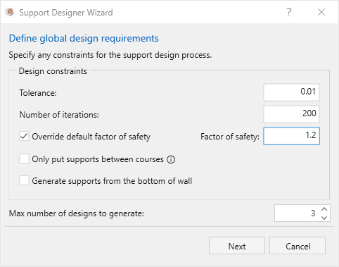
Design Constraints are available to better calibrate the potential solution:
- Tolerance controls the convergence precision for optimization (e.g., 0.01); smaller values mean more precise results but longer runtime
- Number of iterations defines the maximum number of optimization cycles before stopping (e.g., 200); larger values allow more thorough searching but increase runtime
- Override default factor of safety allows users to specify a custom minimum factor of safety target instead of using the design standard's default (when unchecked, uses standard-specific defaults of 1.5 for NCMA, 1.0 for other standards)
- Only put supports between courses constrains reinforcement placement to occur only at course boundaries. Unselecting this would allow multiple reinforcements behind one block
- Generate supports from the bottom of wall controls whether reinforcement placement starts from the wall foundation or can begin at any elevation
- Max number of designs to generate limits how many alternative optimized solutions the tool will produce and present for comparison in Preview designs dialog
Define Reinforcement Parameters
Optimization Parameters
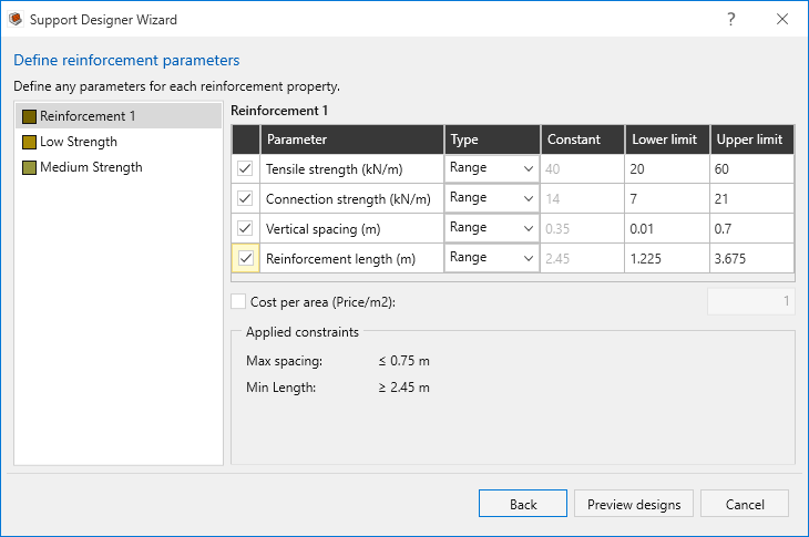
Optimization settings can be configured for each reinforcement type in the wall segment. Users can choose between reinforcements (which have already been defined in Loading and Support > Define Properties) in the left panel and define how each optimizable parameter should be handled.
The following parameters can be optimized (selected using checkboxes) for each reinforcement:
- Allowable tensile strength (static)Tensile strength will not be optimized if the reinforcement is from the manufacturer library
- Connection strength (constant function type)
- Vertical spacing
- Reinforcement length
Optimization type can be either:
- Range: Parameter will be optimized within specified lower and upper limits (e.g., tensile strength between 50-150 kN/m)
- Constant: Parameter remains fixed at a specified value and won't be optimized
Users can specify the cost per area for each reinforcement.
Clicking the Preview designs button will proceed the user to optimize the reinforcement layout according to the provided parameters.
Design Standard Enforcement
The optimization evaluates stability against the load combinations from the selected design standard (AASHTO, NCMA, BS, etc.) and enforces design constraints like maximum spacing limits and minimum reinforcement length requirements, according to the Design reinforcement parameters table above.
The Applied constraints values provided are standard-specific and can be entered into the table for strict standard compliance:
- Maximum spacing (e.g., ≤ 0.75 m per AASHTO)
- Minimum reinforcement length (e.g., ≥ 0.7 H)
Preview and Apply Results
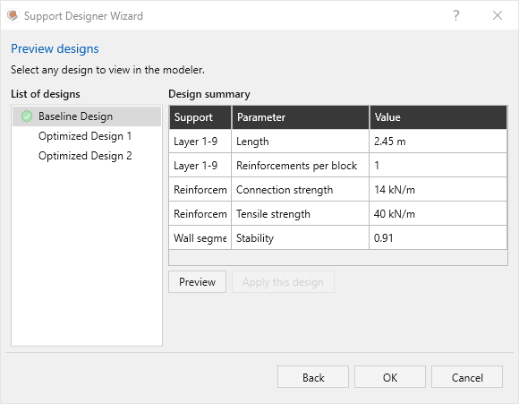
After convergence, users can preview and compare the optimized designs in a table format showing reinforcement types, optimized parameters, stability, and cost.
- Optimized designs are ranked by cost (i.e., “Optimized Design 1” represents the lowest-cost wall according to the provided parameters).
- If the provided parameters prevent the creation of any walls which meet the target stability criteria, feedback will be generated about the governing failure mode.
- Cost per unit width for the designs will only be output if the user has defined a cost per area for each of the reinforcement types in the wall.
- The Preview button allows the use to visualize the layout in the viewport
- Once satisfied, click Apply this design to update the model. Note that if tensile and/or connection strength are optimized, applying the design will modify reinforcement properties to match the optimized values.
- The users are also able to select a different optimized design afterwards by using Loading and Support > Designer > Layout Selection, which opens the Preview Designs dialog.
For a step by step example of the Support Designer feature, see Tutorial 7 - Support Designer.