How to Create a Project
1.0 Introduction
RSLog allows you to log test holes for soil and rock, in geotechnical, environmental, oil and gas, or mining projects.
In this tutorial you will learn how to:
- Create a new project
- Enter test hole data
- Enter soil test results
Want to watch the video version of the tutorial? Check it out here:
2.0 Projects
2.1 Create a New Project
Before you can begin entering test hole data, you must first create a New Project. The Project details define the location and parameters of your geotechnical project.
To create a new Project:
- Select Projects in the navigation panel.
- Click + New Project. A dialog will appear.
- Enter your project details as the following values.
- Enter your Project Title as Project #1 - Proposed development at Burnaby, BC.
- Enter the Client as ABC Client Company Ltd.
Note: Client names can be entered manually or selected from the drop down list of your Contacts - Enter the Site Location as Marine Dr., Burnaby, BC.
Note: The Site Location can be a civic address or geographic coordinates. If an address is not available, you can click on the ‘map icon’ next to the address and set your project location on the map.- Click on the Map icon.
- Use your mouse to drag the pin to a new location on the map (the specific location does not matter for this example).
- Click on the Polygon tool to draw a polygon to represent the site layout. This will be used later for preparation of site location figure, which is typically part of the engineering reports.
- Double click on the map to close the polygon.
- Click Save to close the dialog.
- Once you specify the site location on the map, geographic location of the project will be automatically added to the form.
- Enter the rest of the project information and set the units system and coordinate system as follows:
- Project No. = 121-0061
- Lead Engineer = Alex Smith
- Unit System = Imperial
- Coordinate System = Geographic
- Project Folder Path = H:\2021 Projects\121-0061\
Note: If you don’t have UTM coordinates for your test holes, we highly recommend that you set the project’s coordinate system to Geographic. This allows you to select the test hole locations on the map.
- Your dialog should appear as follows:
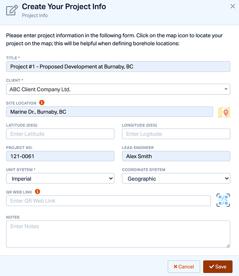
Projects: Create a New Project Tab - Click Save to create the project.
You will then be taken to the list of test holes. Please proceed to section 3.0 Test Holes below.
2.2 Opening an existing Project
If you have multiple projects saved in your RSLog account and wish to edit or enter new Test Hole data, you will need to first open the Project.
To open a Project for data entry or reporting:
- Select Projects in the navigation panel.
- Click on the Click to Open badge below the project you wish to open. This will load the project data.
- Click on the Test Holes menu on the navigation panel to then see the list of all test holes for this project.
3.0 Test Holes
- Click + New Test Hole to begin entering test hole data.
In general, a test hole is made either by ‘drilling’ or by ‘excavating’. As a result, the type of a test hole is either ‘drill hole’ or ‘test pit’.
3.1 General
- In the General tab, enter the follow test hole details:
- Test Hole Type = Drill hole
- Name = AH21-01
- Depth (ft) = 35
- Inferred Groundwater Level (ft) = 8.5
- Start Date =
- End Date =
- Logged by = JT
- Reviewed by = AF
- Hole diameter (in) = 5
- Notes = Auger hole located at north portion of the site
- Drill Contractor = ABC Drilling Inc
- Equipment = Track Rig B52
- Under Test Hole Plumbness click on Open Settings.
This section allows you to specify the ‘trend’ and ‘plunge’ if you have a borehole that is not drilled vertically. - Leave the default values of Trend = 0° and Plunge = 90°. Click OK to close the dialog.
- Enter the test hole's coordinates and elevation:
- Latitude = 49.20699366352015
- Longitude = -123.00402913686655
- Elevation (ft) = 36.5
Note: While coordinates are not necessarily required for a test hole, in order to benefit from the other RSLog features such as GIS or ‘cross section’ design, we recommend that even if you don’t have UTM coordinates for your test holes, specify their locations on the map by clicking Click to Locate on Map. This way RSLog will save the geographic coordinates of the test holes.
- Your dialog should appear as follows:
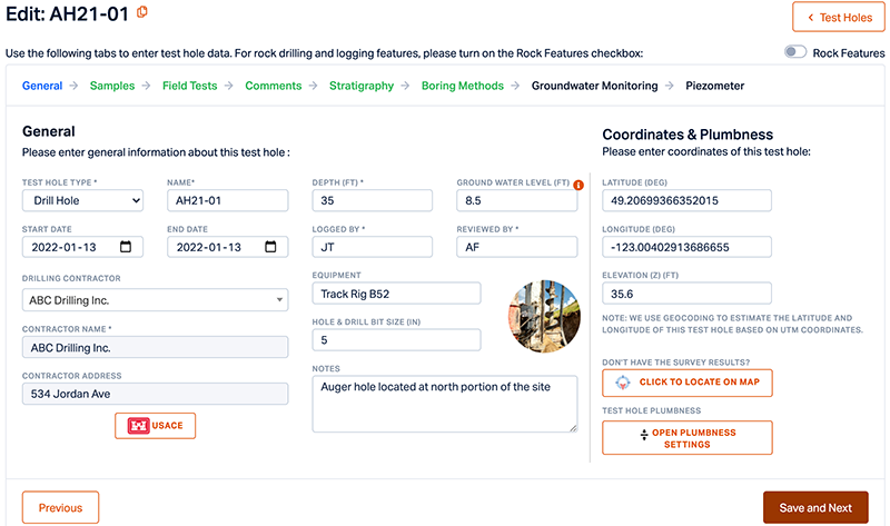
Test Hole: General Tab - Click Save and Next button to go to the next tab.
3.2 Samples
On the Samples tab, you can add a list of all samples taken from this test hole. You can also specify start and end depth for each sample.
- Click + New Sample.
- Enter the following sample details:
- Depth (ft) = 1.5
- TO (ft) = 2.0
- Sample NO. = S1
- Sample Type = Auger Sample
- Colour = Grey
- Sample Description = Silty sand with trace gravel, moist, inferred to be compact
- Click Save to add the sample and close the dialog.
- Your dialog should appear as follows:
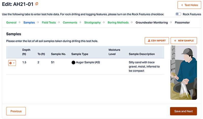
Test Hole: Samples Tab - Click Save and Next to go the next tab.
3.3 Field Tests
RSLog supports various types of field tests, from Standard Penetration Test to Vane shear test or manual DCP sounding.
To add Field Test data:
- Go to the Test Type drop down menu and select Dynamic Cone Penetration Test.
- Enter a Depth of 1 ft.
- Enter a Value of 10.
- Click Add or press Enter to save the record.
- Repeat the same steps to add more records for your Field Test.
| Test Type | Depth | Value |
| Dynamic Cone Penetration Test | 2 | 13 |
| Dynamic Cone Penetration Test | 3 | 18 |
| Dynamic Cone Penetration Test | 4 | 19 |
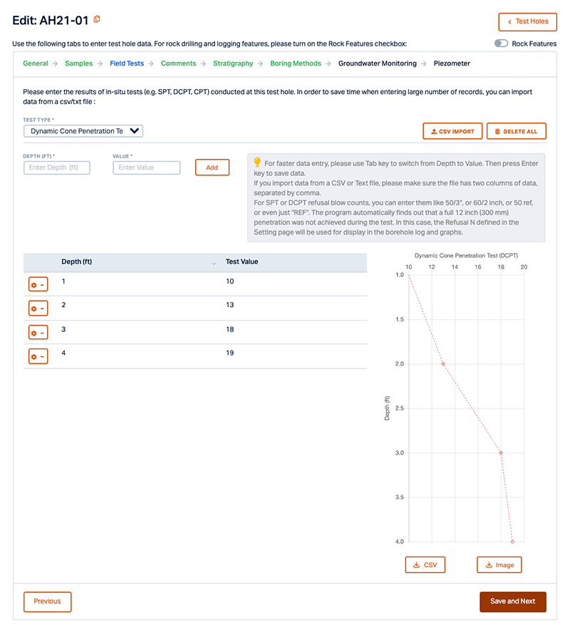
The graph is refreshed as you enter field test data. You can save the graph as an image, or export data to CSV format.
Import Field Test Data
If you already have your field test data, click on the Import Data button and select the CSV file to import the data into RSLog.
- When you are done entering Field Test Data, click Save and Next to go to the next tab.
3.4 Comments
The Comments tab allows you to add comments for specific depths along the test hole. These comments are shown in the borehole logs.
To add a Comment:
- Click + New Comment.
- Enter the Depth as 5 ft.
- In the Comment field enter: "slight seepage at 5ft depth."
- Your dialog should appear as follows:
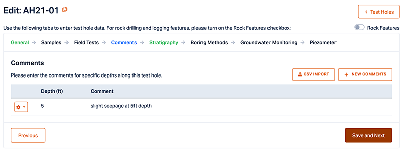
Test Hole: Comments Tab - Click Save to save the comment.
- Click Save and Next to go the next tab.
3.5 Stratigraphy
The Stratigraphy tab is used to enter different subsurface soil or rock layers that were encountered during the field investigation.
- Click + New Soil Layer.
- Enter the depth to top and bottom of the layer: From Depth = 0 ft. and To Depth = 3.5 ft.
- Enter Layer Title as Fill Material (sand).
- Under Layer Symbol for Shading (or hatch style) select Soil. The Layer Symbol for Shading is the hatch or shading shown for this layer in the borehole log.
Note: If you don’t want to draw any symbol or hatch for a specific layer, select the ‘None’ option. - From the Soil drop-down menu, you can see a list of USCS and AASHTO standard soil classifications to choose from. Select FL (Fill Material).
- In the Layer Description field type ‘Silty sand with trace gravel, moist, inferred to be FILL’
You can specify the type, thickness, and color for the line drawn at the bottom of this layer in the borehole log. You can also enter the estimated unit weight of this layer.
- Enter the following values for the Line at bottom of layer:
- Line Style (Bottom) = 3) Solid
- Line Thickness = 1) Thin or 0.5px
- Line Color = Black
- Enter the following values for Eng. Analysis:
- γ (LB/FT3) = 120
- Fines Content (%) = 5
- Your dialog should appear as follows:
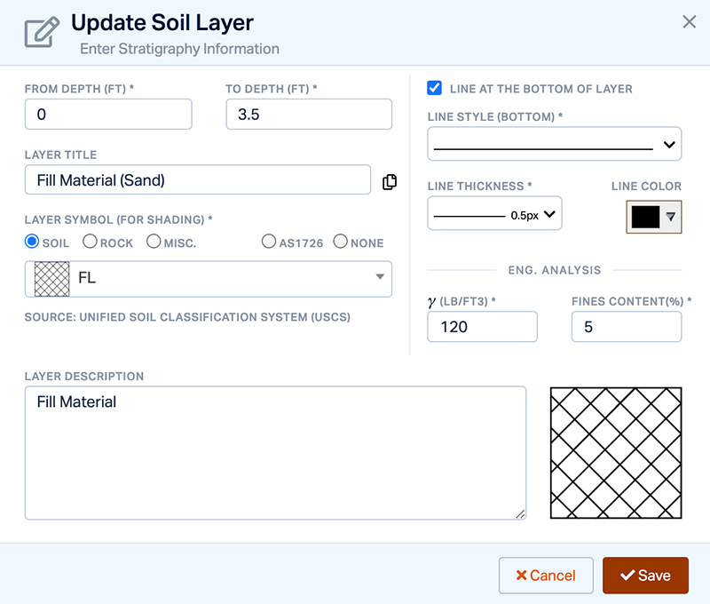
Test Hole: Stratigraphy Tab - Click Save to save the entry.
- Click Save and Next to move to the next tab.
3.6 Boring Methods
For drill holes, you can specify the boring method.
- Click +New Boring Method.
- Enter the depth to top and bottom of the layer: From Depth = 0 ft. and To Depth = 35 ft.
- Select Auger (Solid-Stem) as the Drill Method from the drop-down list and enter Track Rig B52 on the Type of Drill Rig field.
- Hit the ✔️Save button.
- Your dialog should appear as follows:
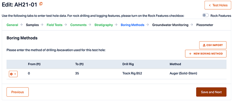
Test Hole: Boring Methods Tab - Click Save and Next to proceed to the next tab.
3.7 Groundwater Monitoring
When groundwater level is present in the test hole, use this tab to enter groundwater measurements. Simply enter the groundwater depth, date, time, and weather condition at the time of measurement once the Groundwater Info tab appears. You can enter multiple groundwater measurements for each test hole.
- Click + New Reading and enter the following values:
- Water Level (ft) = 8.5
- Date = 02/06/2021
- Time = 03:20 PM
- Weather Condition / Notes = Sunny
- Hit the ✔️Save button.
- Click + New Reading again to add another record with the following values:
- Water Level (ft) = 6.7
- Date = 02/09/2021
- Time = 08:24 PM
- Weather Condition / Notes = Sunny
- Your dialog should appear as follows:
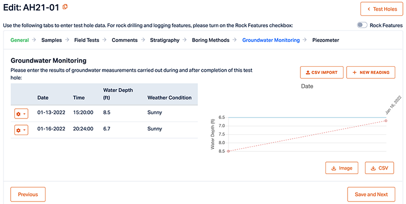
Test Hole: Groundwater Monitoring Tab - Click Save and Next to proceed to the next tab.
3.8 Piezometer
If a piezometer is installed at this test hole, use this tab to enter piezometer data. You can specify the type of piezometer and the ‘plug’ used at the top of piezometer.
- From the Piezo Type drop-down list select Standpipe and enter the Plug Type as J Plug.
- Start adding ‘pipe segments’ by clicking + New Pipe Segment.
Note: Each pipe segment is shown differently in the borehole log, depending on the type of pipe and how that segment is backfilled.
- Enter the following values once the Piezometer Info tab is prompted:
- From (ft) = 0
- To (ft) = 8
- Pipe Type = Solid
- Backfill Material = Filter Sand
- Hit the ✔️Save button.
- Repeat steps 2 to 4 and add three more records for your Piezometer.
From (ft) |
To (ft) |
Pipe Type |
Backfill Material |
8 |
13 |
Slotted |
Filter Sand |
13 |
20 |
Solid |
Bentonite Chips |
20 |
35 |
No Pipe |
Drill Cuttings |
- Your dialog should appear as follows:
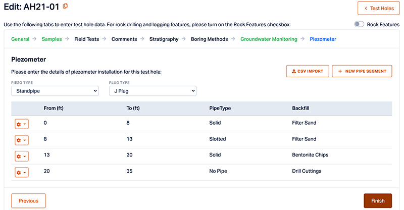
Test Hole: Piezometer Tab - Add as many pipe segments as necessary and click Finish.
Congratulations! You have just finished creating your first test hole. You can always edit or delete a test hole from the list of test holes on this page by clicking the Settings drop-down and selecting the Edit or Delete option when necessary.