2 - Heavy Support
1.0 Introduction
This tutorial demonstrates how to model a tunnel with much more serious stability problems than you saw in Tutorial 1 - RockSupport Quick Start.
Topics covered in this tutorial:
- Carranza-Torres Solution Method
- Deterministic Analysis
- Tunnel and Rock Parameters
- Adding Support
Finished Product:
The finished product of this tutorial can be found in the Tutorial 02 Heavy Support.rsp file, located in the Examples > Tutorials folder in your RocSupport installation folder.
1.1 Problem Description
This tutorial demonstrates how to model a tunnel with much more serious stability problems than you saw in Tutorial 1 - RockSupport Quick Start, requiring heavier support. The Carranza-Torres solution method will be used to determine the Ground Reaction Curve. Analysis will be Deterministic (all parameters assumed to be exactly known).
The model used in the analysis is a 10 meter diameter tunnel is to be constructed at a depth of 75 meters in a rock mass whose strength is defined by the Hoek-Brown criterion with an intact rock strength σci = 4 Mpa, constant mi = 12 and a Geological Strength Index = 17.
2.0 Model Creation
If you have not already done so, run RocSupport by double-clicking on the RocSupport icon in your installation folder or by selecting Programs > Rocscience > RocSupport > RocSupport on the Start menu. If the RocSupport application window is not already maximized, maximize it now, so that the full screen is available for viewing the model.
To begin creating the model:
- Select File > New

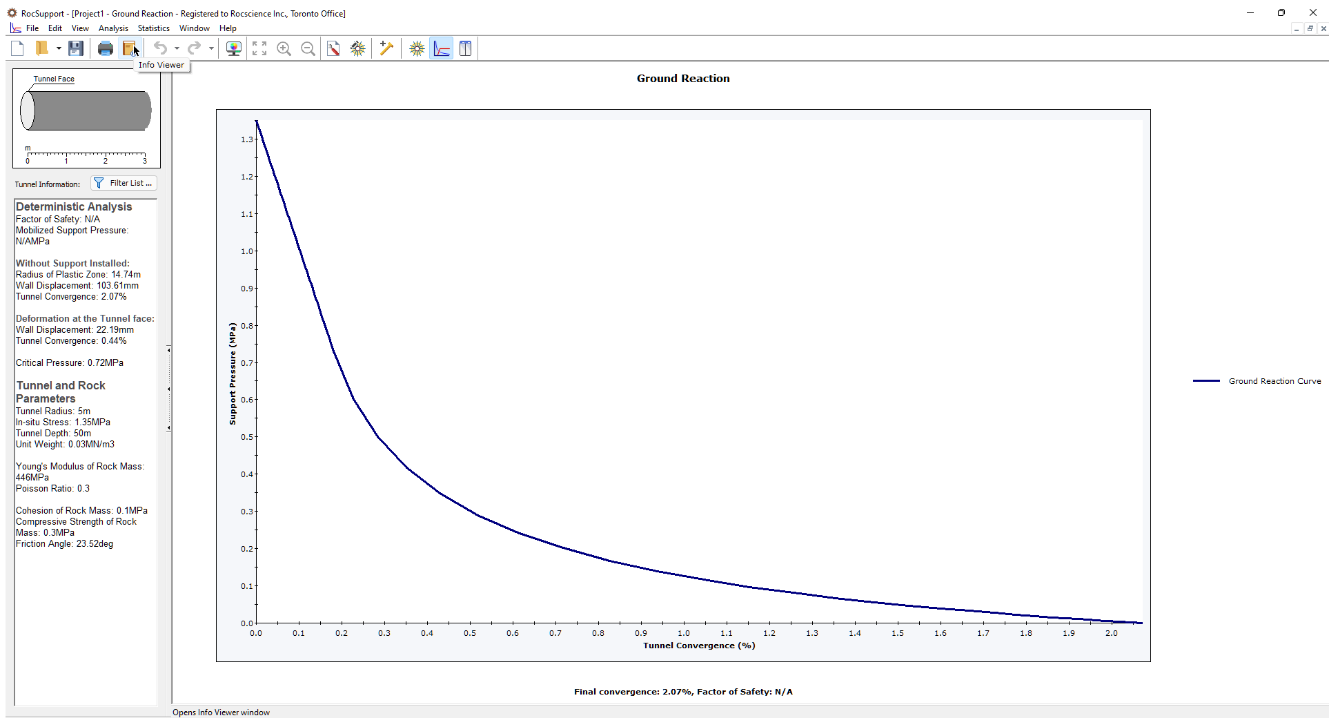
When a new file is created, the Ground Reaction View is displayed. The view shows the Ground Reaction Curve based on the default Tunnel and Rock Parameters.
2.1 PROJECT SETTINGS
For this example, we will use the Carranza-Torres solution method, which must be selected in the Project Settings dialog.
- Select Analysis > Project Settings
 in the menu or click on the icon in the toolbar.
 - In the General tab, set Solution Method = Carranza-Torres (2004).
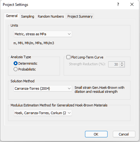
- In the Project Summary tab, enter Tutorial 2 Heavy Support as the Project Title.
- Click OK.
2.2 TUNNEL AND ROCK PARAMETERS
Recall that Tutorial 1 used the Duncan Fama Solution Method and, therefore, the Mohr-Coulomb failure criterion. The Carranza-Torres (2004) solution method uses the Hoek-Brown failure criterion to determine the Ground Reaction Curve and plastic zone radius.
- Select Analysis > Tunnel and Rock Parameters
 in the menu or click on the icon in the toolbar.
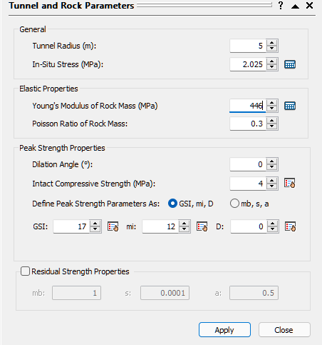
The Tunnel and Rock Parameters dialog opens.
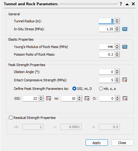
Our tunnel diameter is 10 meters, so the default Tunnel Radius of 5 meters is already correct and does not need to be changed.
2.2.1 In-Situ Stress
The In-Situ Stress can be estimated from the Tunnel Depth.
- Select the Estimate
 button beside the In-Situ Stress edit box.
The Estimate In-Situ Stress dialog appears. - Enter Tunnel Depth = 75 meters.
The estimated In-Situ Stress is 2.025 MPa.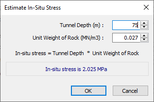
- Click OK.
The In-Situ Stress in the Tunnel and Rock Parameters dialog should now be 2.025.
2.2.2 Rock Parameters
- Back in the Tunnel and Rock Parameters dialog, enter the following:
- Intact Compressive Strength (σci) = 4MPa
- GSI = 17
- Intact Rock Constant mi = 12
NOTE: Built-in tables for selection of appropriate mi , GSI, intact UCS and D can be accessed by selecting the “pick”  buttons in the Tunnel and Rock Parameters dialog. This is left as an optional exercise for the user to explore. See the previous tutorial for a discussion of these tables.
- Click the Calculator icon beside the Young’s Modulus of Rock Mass edit box to calculate the Young’s Modulus of Rock Mass according to the Modulus Estimation Method specified in the Project Settings dialog.
The value should now be 299 MPa. For help on this parameter, see RocSupport Modulus Estimation Method Setting. - Click Apply to save your settings and run the analysis.
- Click Close.
3.0 Analysis Results (No Support)
The Ground Reaction Curve should appear as follows.
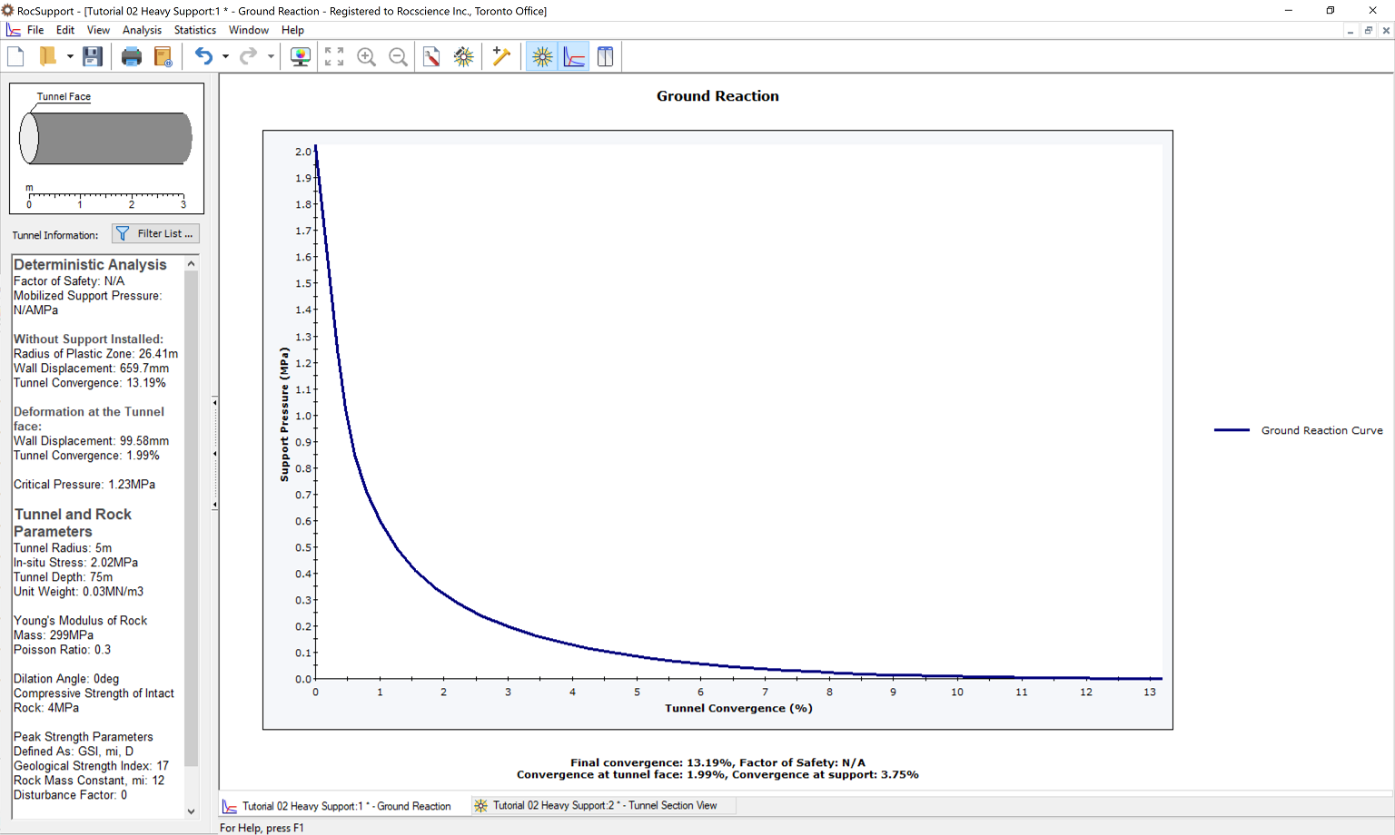
Note the Tunnel Final Convergence is 13.2%. This is a very high value of Tunnel Convergence. A tunnel with these input parameters would have very serious stability problems. Very heavy support, installed as close as possible to the advancing face, would be necessary.
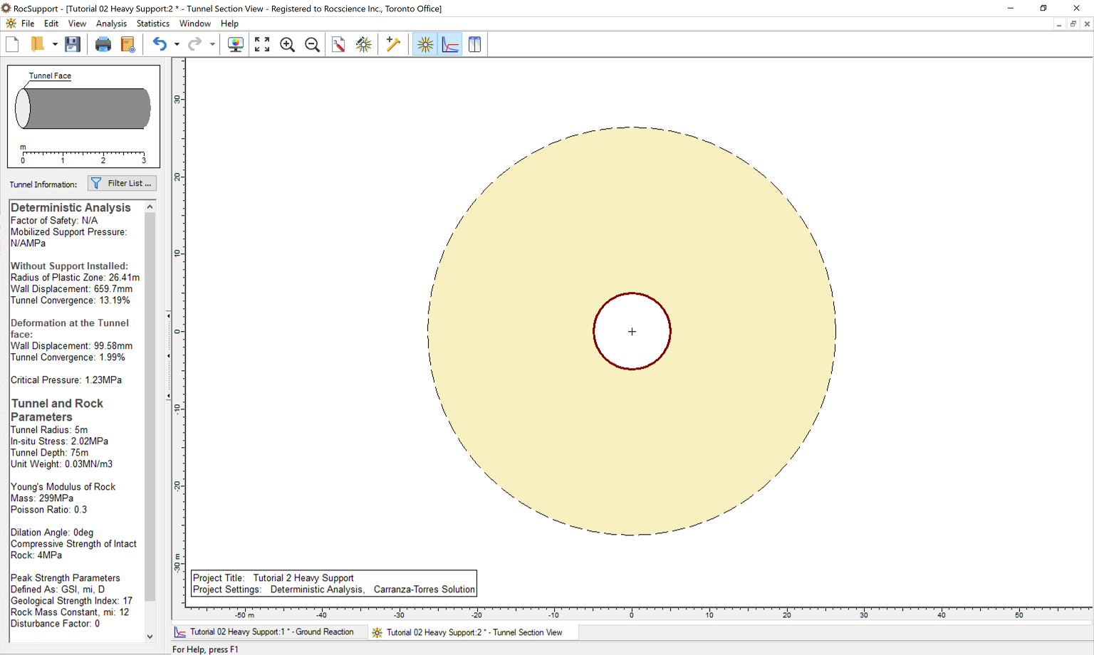
Now we'll look at the model through the Tunnel Section View.
- Select Tunnel Selection
 on the toolbar or Analysis menu.
Notice the very large Radius of Plastic Zone (26.4 m) around the unsupported tunnel.
4.0 Adding Supports
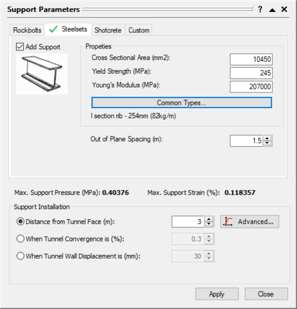
Now we'll add supports, using the Support Parameters dialog. Let’s start with I section steel sets (254 mm depth, 10450 mm2 area, weighing 82 kg / m), spaced at 1.5 m, and installed at a distance of 3 m from the face.
- Select Support Parameters
 on the toolbar or the Analysis menu.
 - Select the Steel Sets tab and select the Add Support check box.
- Select I section rib from the Common Types library.
- Make sure Section depth = 254 is selected.
- Set Out of Plane spacing = 1.5m.
- Under Support Installation, select Distance from Tunnel Face and enter 3m.
- Click Apply to save the support parameters you have entered and re-run the analysis.
- Click Close.
5.0 Analysis Results (with Support)
- Select the Ground Reaction
 view.
view.
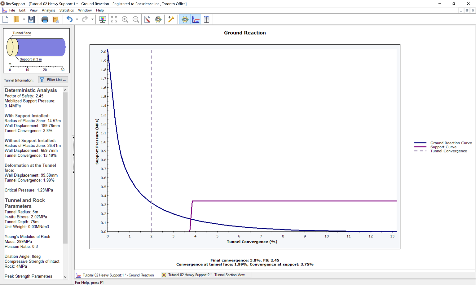
The Ground Reaction and Support Reaction should appear as follows:
Select the Tunnel Section View and view the analysis summary in the Project Info Textbox.
- Select: Analysis > Tunnel Section

Compared to the unsupported results, the Steel Set support has:
- Decreased the plastic zone radius (26.4 to 14.6 m)
- Decreased the final Tunnel Convergence (13.2 to 3.8 %)
- Factor of safety for the support is 2.5.
6.0 Additional Support
Let’s now see the effect of adding a layer of shotcrete in addition to the steel set support.
- Select Support Parameters on the toolbar or the Analysis menu.
- In the Support Parameters dialog, select the Shotcrete tab.
- Select the Add Support check box and select 100 mm Thickness shotcrete from the Common Types library.
- Note the combined Maximum Support Pressure (1.034) and Maximum Support Strain (0.118 %), of the shotcrete and the steel sets
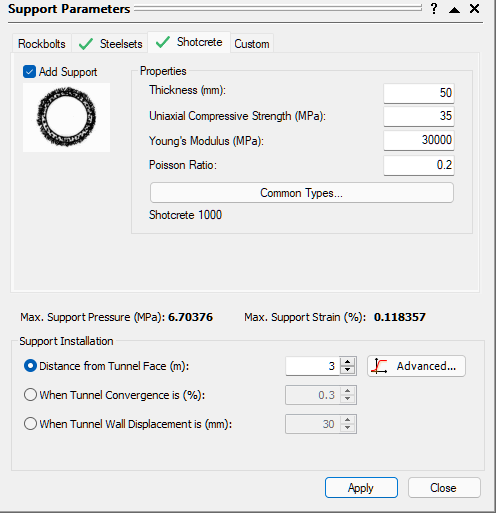
- Select Apply and then Close.
NOTES:
- The safety factor of the combined support system has more than doubled (2.5 to 7.3).
- However, this has not significantly reduced the final Tunnel Convergence or the Plastic Zone Radius.
Let’s look at the Ground Reaction / Support Reaction plot to examine why the shotcrete support has not affected the final convergence or Plastic Zone Radius.
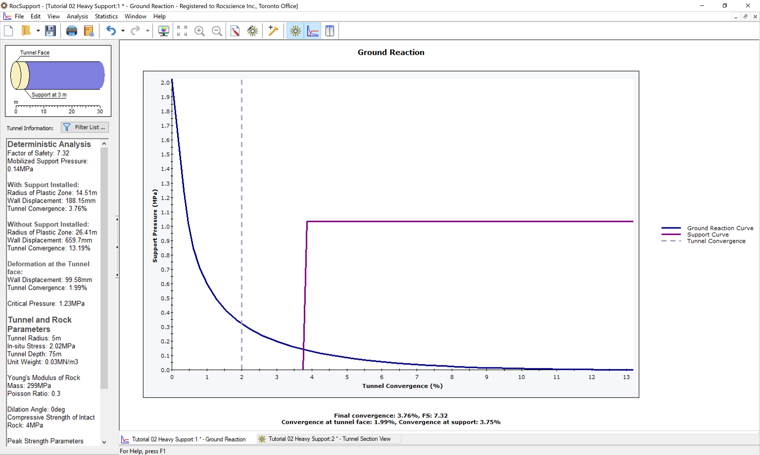
If we compare the combined Support Reaction curve, to the curve for the Steel Sets alone, you will note the following:
- the additional shotcrete support, has approximately doubled the Maximum Support Pressure, hence the Factor of Safety increase from 4.3 to 7.3.
- However, the intersection point of the Ground Reaction and Support Reaction curve, has not changed significantly, hence there is no significant change in the final Tunnel Convergence or Plastic Zone radius.
In this example, the intersection of the Ground Reaction and Support Reaction is affected primarily by the Distance From Face (entered in the Support Parameters dialog). We did not change this value when we added the shotcrete support.
6.1 SUPPORT INSTALLATION
As a final exercise, enter different values for the Distance from Face in the Support Parameters dialog (e.g. 2 meters, 1 meter etc), and select Apply to re-calculate and view the results.
Notice that changing the Distance from Face shifts the origin of the Support Reaction curve. This DOES have an effect on final Tunnel Convergence, Plastic Zone Radius, and Factor of Safety for the Support. The Factor of Safety decreases as the Distance From Face decreases, because the Support takes a greater load as it is installed closer to the face.
The user is encouraged to experiment with the Support Parameters dialog. Parametric analysis can be performed very quickly, by adding or removing support, changing support parameters, and selecting Apply to re-calculate the results. Observe the effects on the Support Reaction Curve.
7.0 Comment on Tutorial 2
A tunnel with the input parameters used for this example, would certainly require very detailed final support design, which would include numerical analysis such as finite element.
A rock-support interaction analysis of such a tunnel, as demonstrated here using RocSupport, would not be adequate for final design purposes. See the guidelines in the Appendix (“category E ”), for the expected support design issues for this tunnel.
Nonetheless, valuable insight into the tunnel behaviour can be gained from the use of RocSupport even in such cases. Quick parametric analysis is very easy to perform in RocSupport, allowing the user to vary all input parameters, and view the effect on the results.
This concludes Tutorial 2 Heavy Support.