9 - Convergence-Confinement Method for TBM segmental lining design (Almog et al. 2015)
1.0 Introduction
In RocSupport, analytical methods known as Convergence-Confinement Methods (CCM) are used to find the tunnel convergence due to ground loading. These methods do not account for the ground relaxation induced by the pressurized shields of TBMs. A new method which uses the same principles is therefore required for which the equations of the Ground Reaction Curve (GRC) and the Longitudinal Displacement Profile (LDP) are modified (Almog et al. 2015).
In this tutorial, we will analyze two tunnels to investigate the effects of TBM effective confining pressure on the tunnel convergence by using the method proposed by Almog et al. (2015).
The following assumptions are made:
- Effective stresses are considered for the analysis
- The Duncan-Fama solution is used
- The ground material remains fully elastic below its critical pressure
- For TBM effective confining pressure greater than 0, the GRC and LDP is modified according to Almog et al. (2015)
Topics Covered in this tutorial:
- Ground relaxation in Convergence-Confinement Method
- Effects of TBM effective confining pressure on Ground Reaction Curve
- Effects of TBM effective confining pressure on Longitudinal Displacement Profile
- Tunnel convergence
Finished Product:
The finished product of this tutorial can be found in the Tutorial 09 Convergence-Confinement Method for TBM segmental lining design (Almog et al. 2015) file located in the Examples > Tutorials folder in your RocSupport installation folder.
2.0 Model Creation
If you have not already done so, run the RocSupport program by:
- Double-click the RocSupport icon in your installation folder or select Programs > Rocscience > RocSupport > RocSupport in the Windows Start Menu.
When the program starts, there are no Models loaded. You need to create a new project as follows:
- Select: File > New

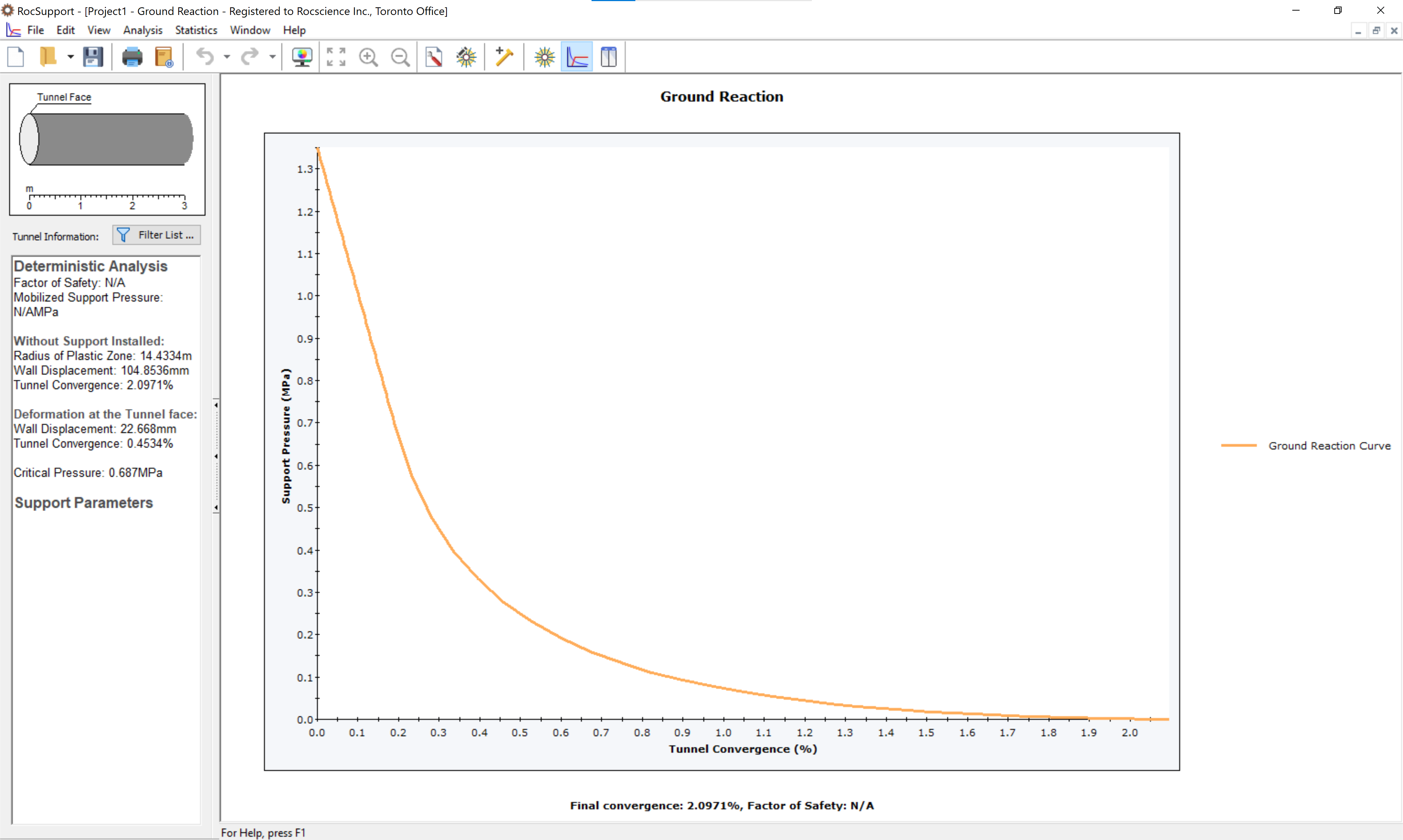
Whenever a new file is created, the Ground Reaction View is displayed. The view shows the Ground Reacion Curve based on the default Tunnel and Rock Parameters.
If the RocSupport application window is not already maximized, maximize it now so that the full screen is available for viewing the model.
We will now set up the model environment in the following dialogs:
- Project Settings
- Tunnel and Rock Parameters
- Support Parameters
2.1 Project Settings
Set the model Units, and Analysis Type in the Project Settings dialog.
- Select Analysis > Project Settings

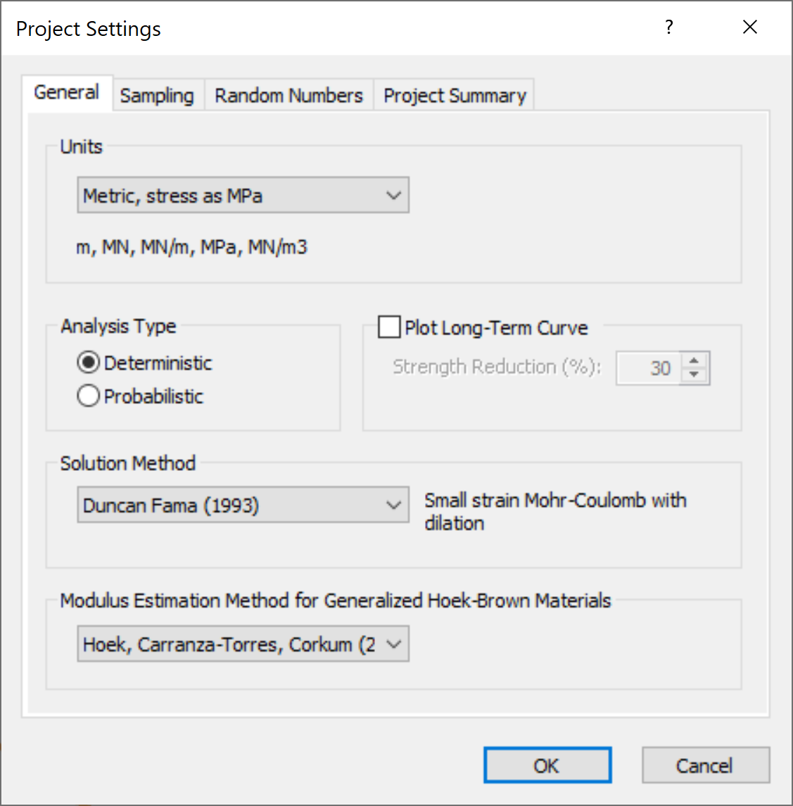
- In the General tab enter:
- Units = Metric, stress as MPa
- Analysis Type = Deterministic
- Solution Method = Duncan Fama (1993)
- Modulus Estimation Method for Generalized Hoek-Brown Materials = Hoek, Carranza-Tores, Corkum (2002)
2.2 Tunnel and Rock Parameters
Open the Tunnel and Rock Parameters dialog:
- Select: Analysis > Tunnel Parameters

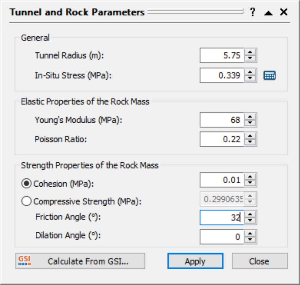
- Enter the following data into the dialog:
- Tunnel Radius = 5.75 m
- In-Situ Stress = 0.339 MPa
- Young’s Modulus = 68 MPa
- Poisson’s Ratio = 0.22
- Cohesion = 0.01 MPa
- Friction Angle = 32 degrees
- Dilation Angle = 0 degrees
The dialog should look as follows:
2.3 Support Parameters
When considering supports in the analysis of tunnel excavation, the GRC and LDP are required to relate tunnel wall deformations to the actual physical location along the tunnel axis. In the analysis of TBM tunnel linings using CCM, the pressure from the pressurized shield counteracts the pore water pressure in the ground and provides a partial restraint to the insitu effective stresses. This partial restraint is referred to as the relaxation factor. Both the GRC and LDP are affected by this relaxation factor. To see the effects of TBM pressure on the GRC and LDP, we will add supports using the Support Parameters dialog.
- Select Support Parameters
 on the toolbar or the Analysis menu
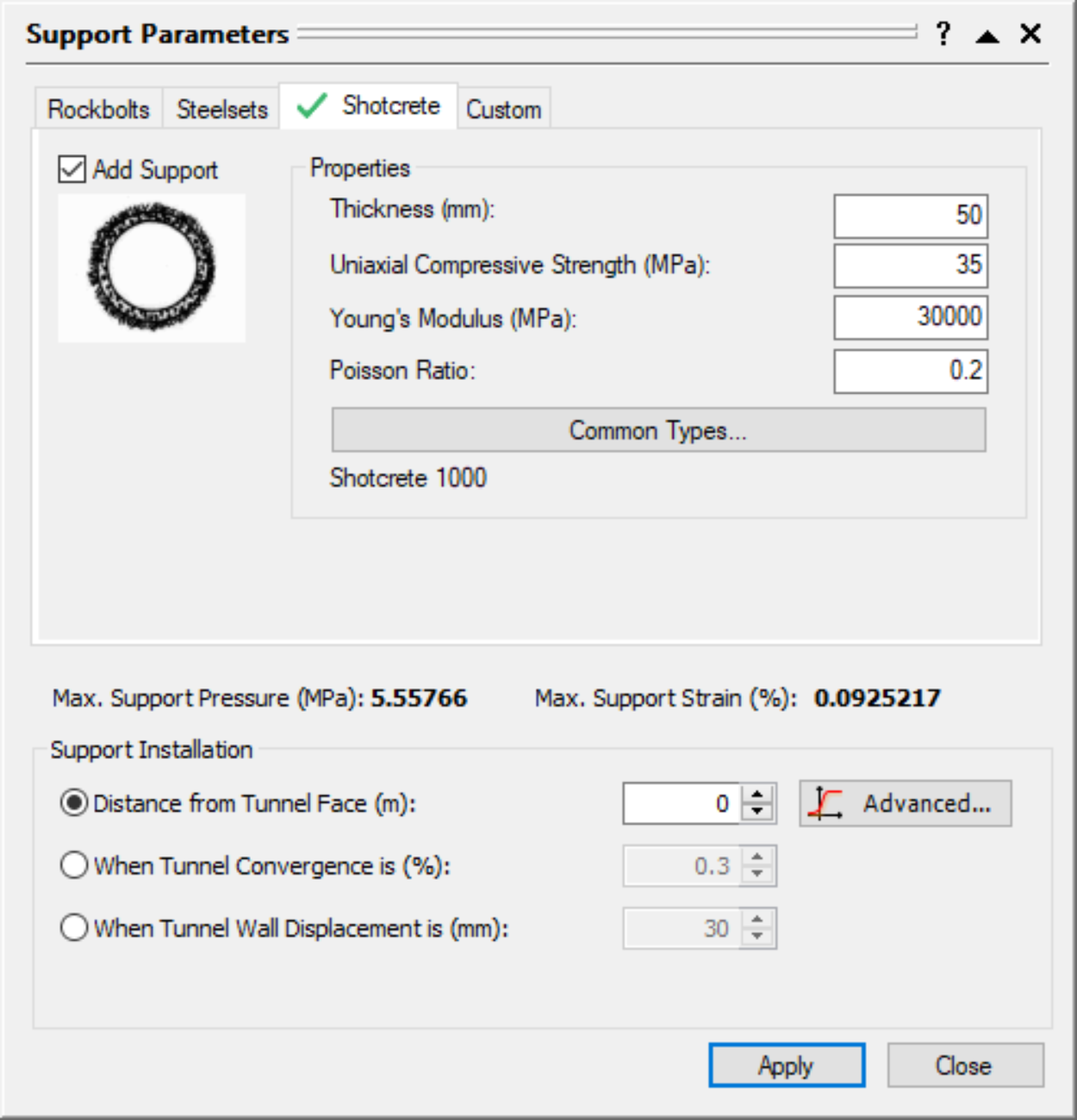
 - Select the Shotcrete tab and select the Add Support check box
- Set the Distance from Tunnel Face = 0 m and keep the remaining default parameters set for Shotcrete as shown below
- Under Support Installation, click on Advanced to open the Longitudinal Deformation Profile dialog
- Click on the drop-down menu and select Almog et al. (2015)
- Set the TBM effective confinement pressure = 0 MPa
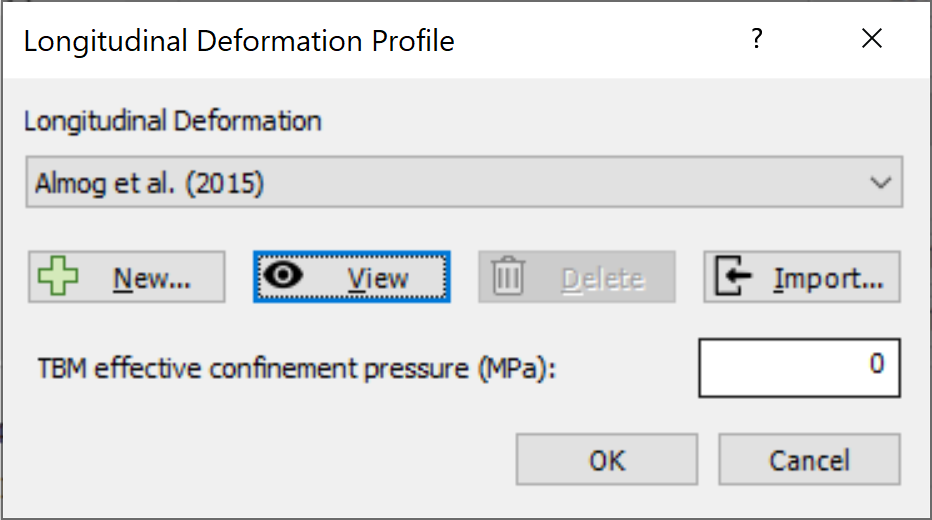
- Click on View to see and export the Longitudinal Displacement Profile Graph
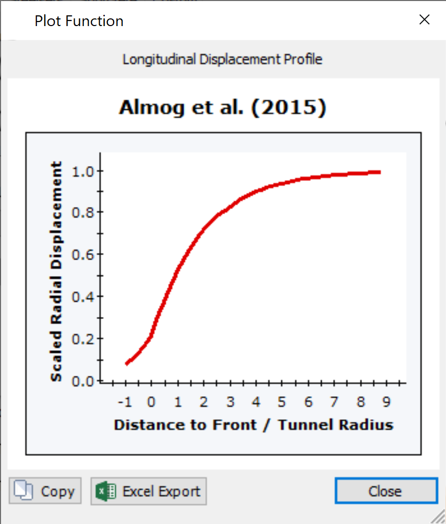
- Click Apply to save the support parameters you have entered and click Close
3.0 Analysis Results
The Ground Reaction and Support Reaction should appear as follows:
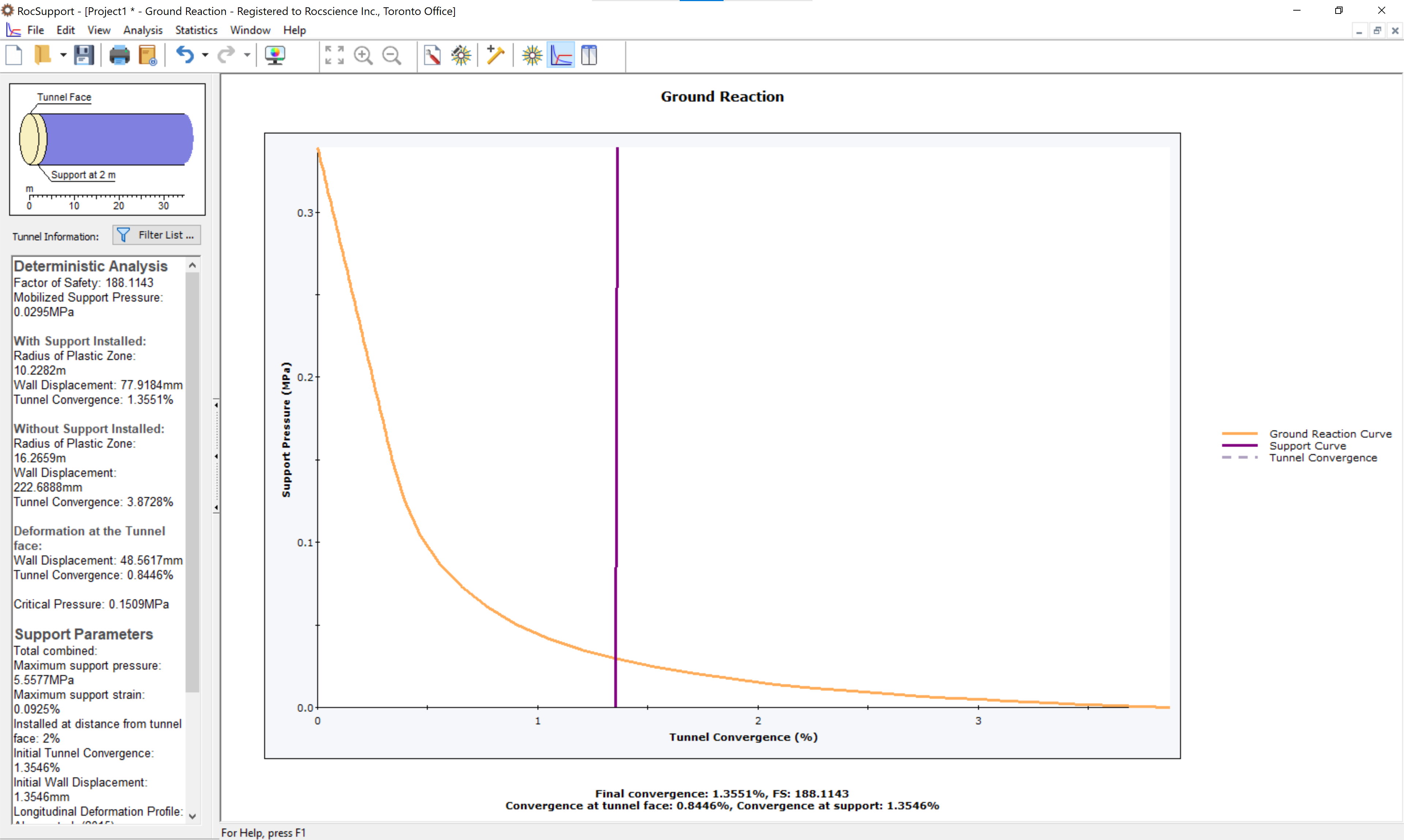
3.1 Results of model without TBM effective pressure
When the TBM pressure is smaller than the pore water pressure i.e. the TBM effective confining pressure is equal to 0, the results are the same as the results produced if the Longitudinal Deformation method used was Vlachopoulos and Diederichs (2009). This is because the LDP proposed by Almog et al. (2015) is derived from Vlachopoulos and Diederichs (2009) and the GRC remains the same without any TBM effective confining pressure.
- To view the results, click on the Info Viewer

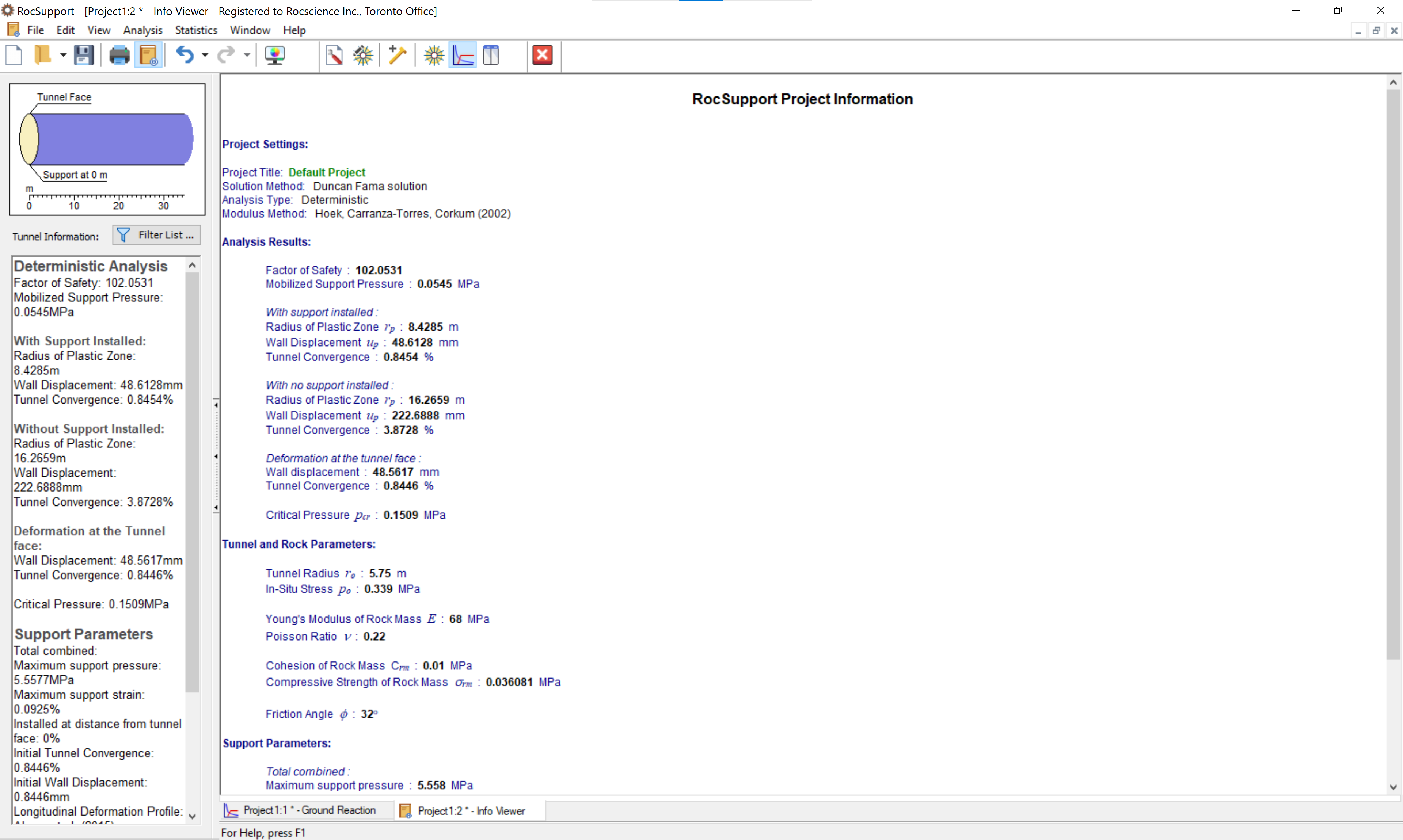
The table below summarizes the analysis results using Vlachopoulos and Diederichs (2009) and Almog et al. (2014) with TBM effective confining pressure set to 0 MPa.
Result Description | Vlachopoulos and Diederichs (2009) | Almog et al. (2015) |
Factor of Safety | 102.05 | 102.05 |
Mobilized Support Pressure (MPa) | 0.05 | 0.05 |
Critical Pressure (MPa) | 0.15 | 0.15 |
With Support Installed | ||
Radius of Plastic Zone (m) | 10.23 | 10.23 |
Wall Displacement (mm) | 77.92 | 77.92 |
Tunnel Convergence (%) | 1.36 | 1.36 |
With No Support Installed | ||
Radius of Plastic Zone (m) | 16.27 | 16.27 |
Wall Displacement (mm) | 222.69 | 222.69 |
Tunnel Convergence (%) | 3.87 | 3.87 |
Deformation at the tunnel face | ||
Wall Displacement (mm) | 48.56 | 48.56 |
Tunnel Convergence (%) | 0.84 | 0.84 |
3.2 Results of model with TBM effective pressure
We will now enter a value of TBM effective confining pressure while still using Almog et al. (2015) to see its impact on the results.
- Select Support Parameters on the toolbar or the Analysis menu
- Under Support Installation, click on Advanced to open the Longitudinal Deformation Profile dialog
- Set the TBM effective confinement pressure = 0.084 MPa
- Click Apply to save the support parameters you have entered and click Close
The Ground Reaction and Support Reaction should appear as follows:
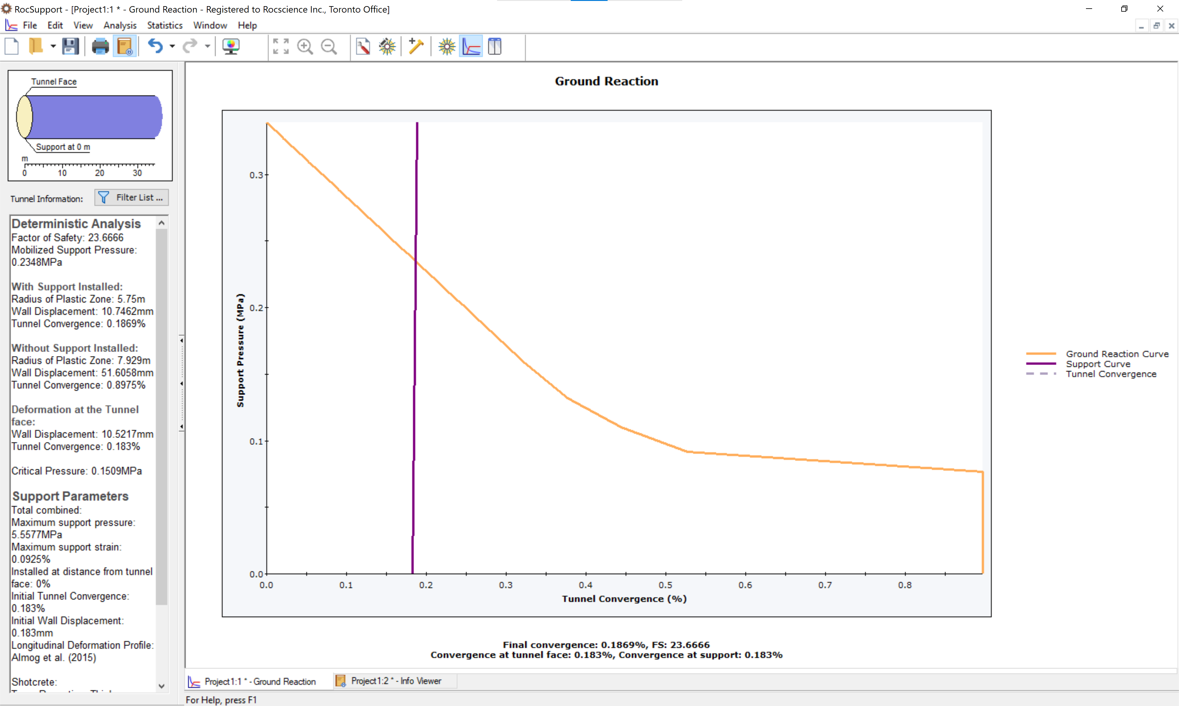
When the TBM pressure is greater than the pore water pressure i.e. the TBM effective confining pressure is greater than 0, the GRC and LDP change and yield different results for the tunnel convergence. This is because the plastic radius decreases with TBM effective confining pressure.
- To view the results, click on the Info Viewer
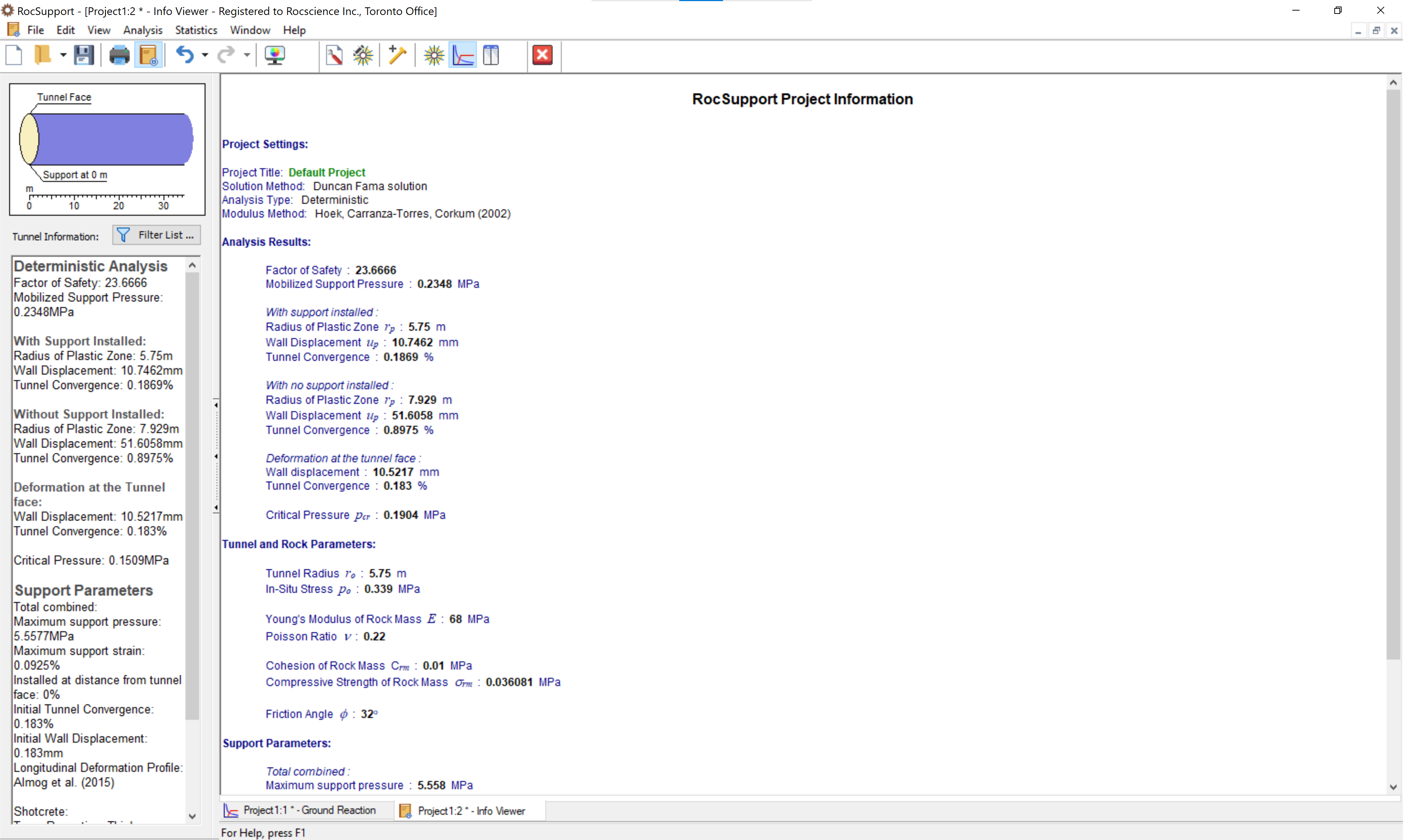
The table below summarizes the analysis results between TBM effective confining pressure set to 0 MPa and TBM effective confining pressure set to 0.084 MPa.
Result Description | TBM effective confining pressure = 0 MPa | TBM effective confining pressure = 0.084 MPa |
Factor of Safety | 102.05 | 23.66 |
Mobilized Support Pressure (MPa) | 0.05 | 0.18 |
Critical Pressure (MPa) | 0.15 | 0.19 |
With Support Installed | ||
Radius of Plastic Zone (m) | 8.43 | 5.75 |
Wall Displacement (mm) | 48.61 | 10.75 |
Tunnel Convergence (%) | 0.84 | 0.19 |
With No Support Installed | ||
Radius of Plastic Zone (m) | 16.27 | 7.93 |
Wall Displacement (mm) | 222.69 | 51.61 |
Tunnel Convergence (%) | 3.87 | 0.90 |
Deformation at the tunnel face | ||
Wall Displacement (mm) | 48.56 | 10.52 |
Tunnel Convergence (%) | 0.84 | 0.18 |
4.0 Conclusion
As shown, the TBM effective confining pressure has a significant impact on the analysis results. The TBM confining pressure reduces the plastic radius which as a result decreases the tunnel convergence at the tunnel face. On the other hand, the reduction in tunnel convergence has for effect an increase in the pressure exerted on the supports. It is also important to note that unlike the concept of volume loss, TBM confining pressure can be directly monitored during construction and are therefore a better way to account for ground relaxation. When using this method, it is advised to use a range of values of TBM confining pressures and to conduct a parametric study to capture its effects on the ground movements and lining design.