9 - Intelligent Support Optimization
1.0 Introduction
This tutorial will demonstrate the ability of RocSlope2 to streamline the support system design process by creating an optimal bolt pattern specific to a project's Design Factor of Safety.
In Tutorial 4 – Support, you learned about manually adding bolt patterns in the analysis. In this tutorial, we will explore the Intelligent Support Optimization feature to automate this process. The Intelligent Support Optimization feature is used to automatically design optimal bolt pattern spacing that satisfies the Design Factor of Safety for all analyzed blocks.
Topics Covered in this Tutorial:
- Intelligent Support Optimization
Finished Product:
The finished product of this tutorial can be found in Tutorial 9 Intelligent Support Optimization.rocslope2 file, located in the Examples > Tutorials folder in your RocSlope2 installation folder.
2.0 Base File
- If you have not already done so, run the RocSlope2 program by double-clicking the RocSlope2 icon in your installation folder or by selecting Programs > Rocscience > RocSlope2 in the Windows Start menu.
When the program starts, a default model is automatically created. If you do NOT see a model on your screen:
- Select File > New

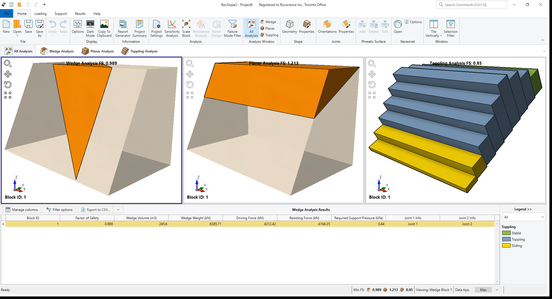
Whenever a new file is created, the default input data forms valid slope geometries for wedge, planar and toppling analysis, as shown in the image below.
This tutorial will use Tutorial 9 – Intelligent Support Optimization (Initial).rocslope2 file as a base model, which includes 8 joint sets and a total of 303 defined joint orientations.
- Select File > Open Project

- Open the Tutorial 9 – Intelligent Support Optimization (Initial).rocslope2 file.
This will open the base file.
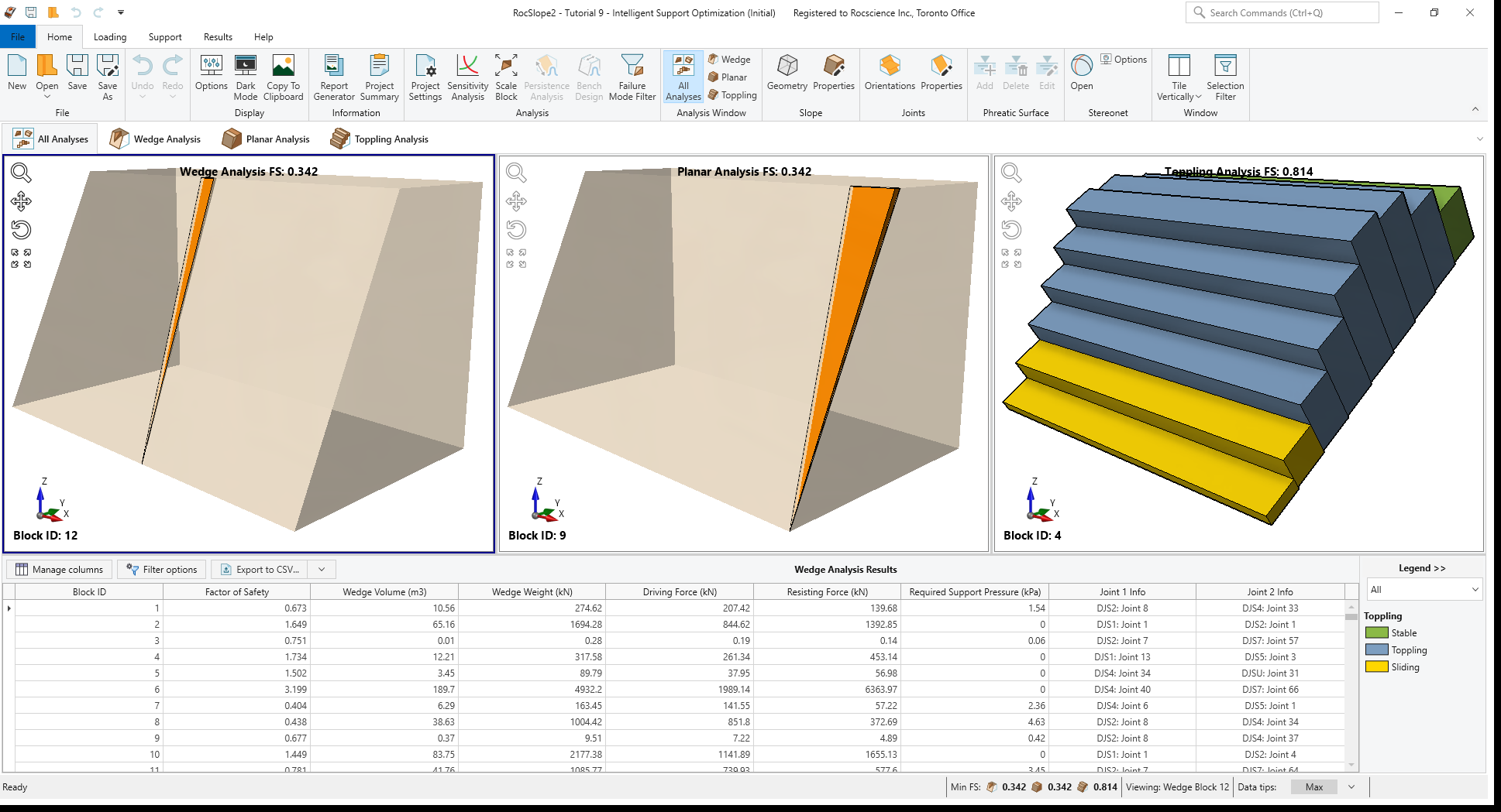
In this base model, we have 9233 Wedge blocks, 12 Planar blocks and 16 Toppling blocks formed.
3.0 Project Settings
Before starting the intelligent bolt pattern optimization process, let’s first look at the Design Factor of Safety for our model.
- Select Analysis > Project Settings

- Go to Analysis and observe the current Design Factor of Safety = 1.
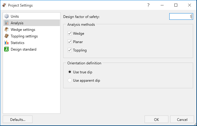
Project Settings dialog - Click OK to close the dialog.
4.0 Intelligent Support Optimization
We are ready to start designing an optimized support pattern that satisfies the Design Factor of Safety for all analyzed blocks.
4.1 Bolt Properties
We first need to set up bolt properties using the Define Bolt Properties dialog.
- Select Support > Properties > Bolts

- Select Bolt Property 1.
- Ensure Support Type = Simple Bolt Force and Force Application = Active.
- Set Force = 100 kN.
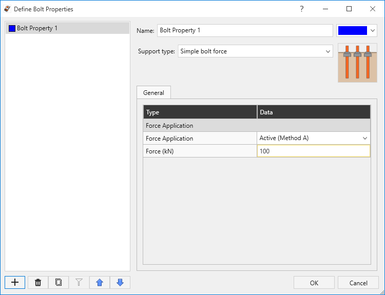
Define Bolt Properties dialog - Click OK to apply changes and close the dialog.
4.2 Add Intelligent Bolt Pattern
Next, we will define the necessary parameters to add an optimized bolt pattern.
- Select Support > Bolt Patterns > Add

- Keep the default parameters as follows:
- Bolt Properties = Bolt Property 1
- Bolt Length = 16
- Orientation = Normal to selected face
- Installation Face = Slope Face
- Select the Use intelligent support optimization checkbox under Bolt pattern configuration.
- Keep the default parameters as follows:
- Pattern = Square
- Horizontal Spacing Interval (m) = 0.5
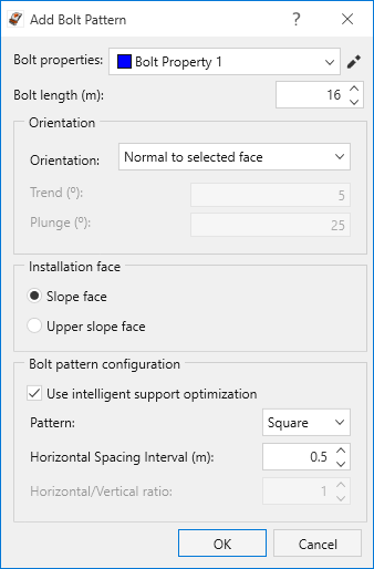
Add Bolt Pattern dialog
- Click OK to accept the changes and apply the optimized bolt pattern.
RocSlope2 automatically looks for the minimum bolt spacing required to meet the Design Factor of Safety for all analyzed blocks. In this case, the minimum horizontal and vertical bolt spacing that satisfies the Design Factor of Safety for all analyzed blocks in a square pattern is 3m * 3m.
The optimized bolt pattern is applied to all blocks in all analysis views and the applied Bolt Pattern Spacing is displayed in the Status Bar at the bottom of the RocSlope2 model. Here, Sx and Sy represent the horizontal and vertical spacing, respectively.
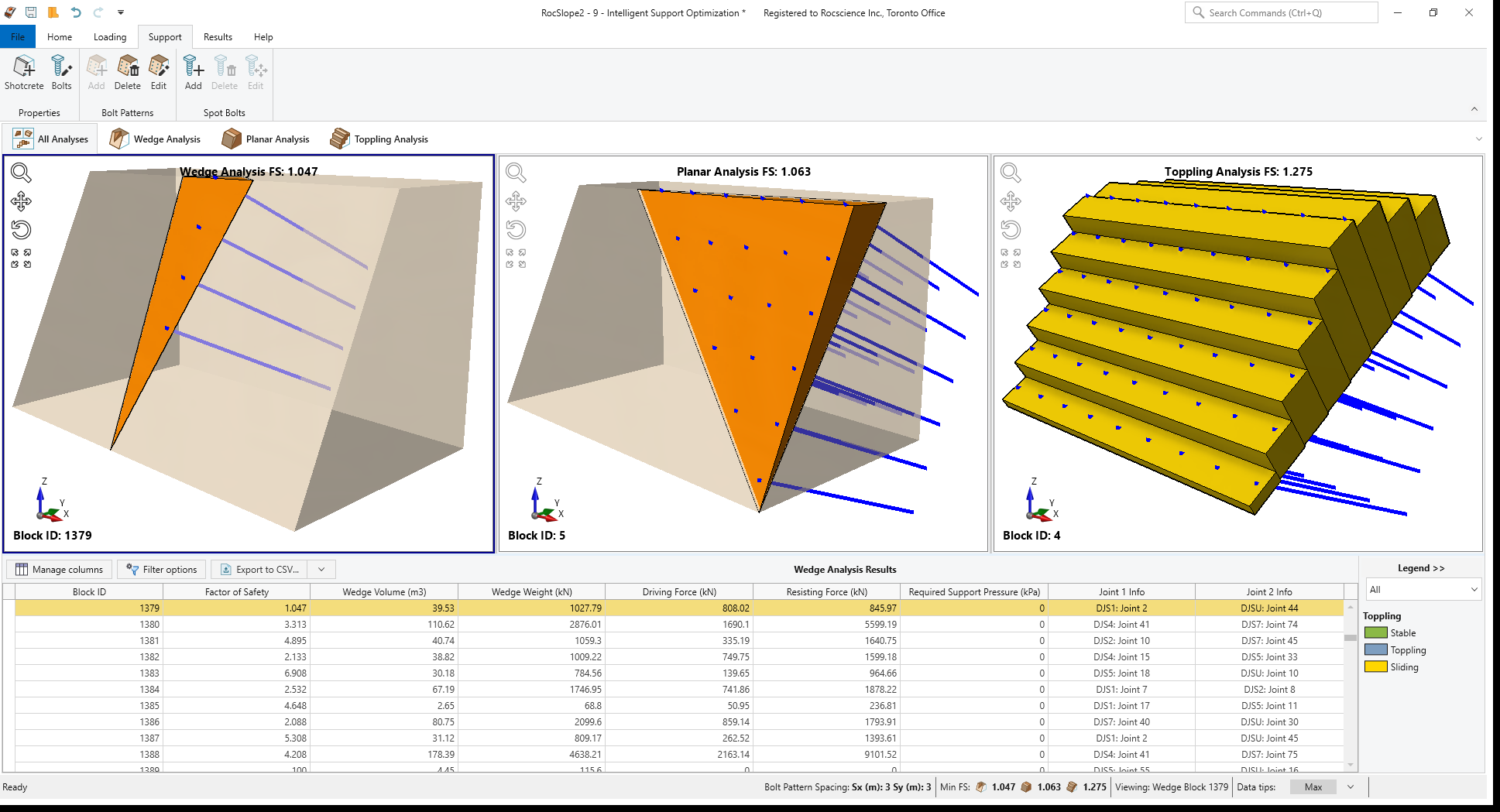
Notice that the lowest calculated Factor of Safety for Wedge Analysis is 1.047, for Planar Analysis is 1.063 and for Toppling Analysis is 1.275. This satisfies the Design Factor of Safety = 1 for all analyzed blocks.
4.3 Edit Bolt Properties
We will now edit the bolt force and let RocSlope2 to intelligently re-optimize the bolt spacing according to modified bolt force. The general rule here is: When an input parameter is added or modified, RocSlope2 will recalculate the results and re-optimize the bolt spacing accordingly.
- Select Support > Properties > Bolts
- Change Force = 75 kN.

Define Bolt Properties dialog - Click OK to apply changes and close the dialog.
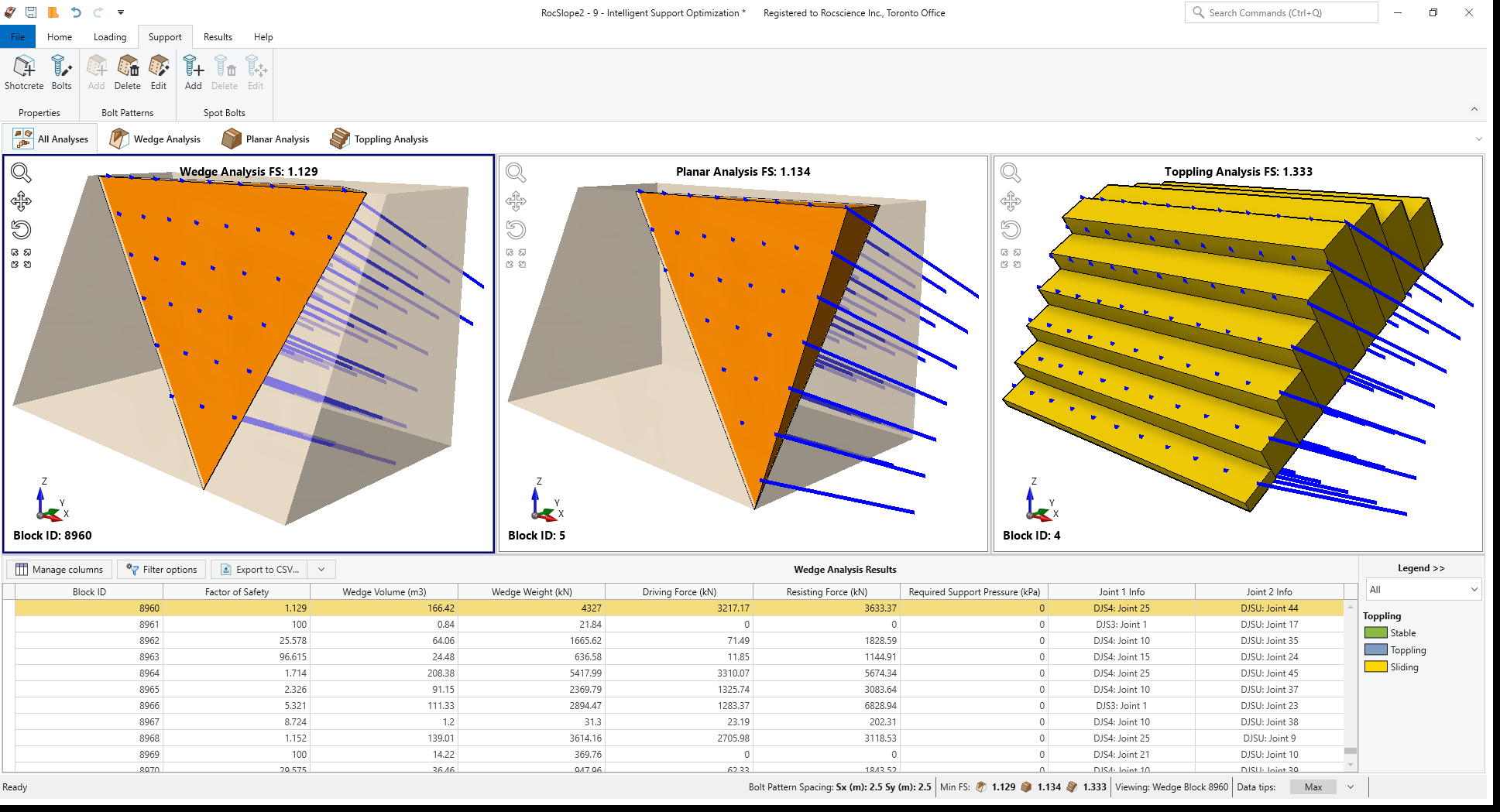
New minimum horizontal and vertical bolt spacing that satisfies the Design Factor of Safety for all analyzed blocks in a square pattern is 2.5m * 2.5m. The minimum required bolt spacing has reduced as expected, since we have defined a lower capacity bolt.
The lowest recalculated Factor of Safety for Wedge Analysis is 1.129, for Planar Analysis is 1.134 and for Toppling Analysis is 1.333.
4.4 Edit Optimized Bolt Pattern
The bolt pattern configuration can also be modified by following the steps below.
- Select Support > Bolt Patterns > Edit

- Click on any bolt in any analysis view to select the bolt pattern. The bolt pattern changes color to indicate it's selected.
- Press Enter to open Edit Bolt Pattern dialog.
- Change Bolt pattern configuration as follows:
- Pattern = Rectangle
- Horizontal Spacing Interval (m) = 0.5
- Horizontal/Vertical ratio = 1.5
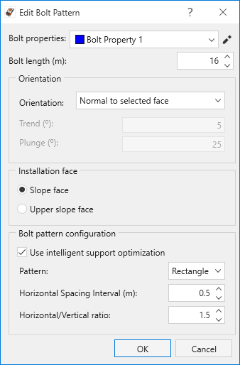
Edit Bolt Pattern dialog
- Click OK to apply changes and close the dialog.
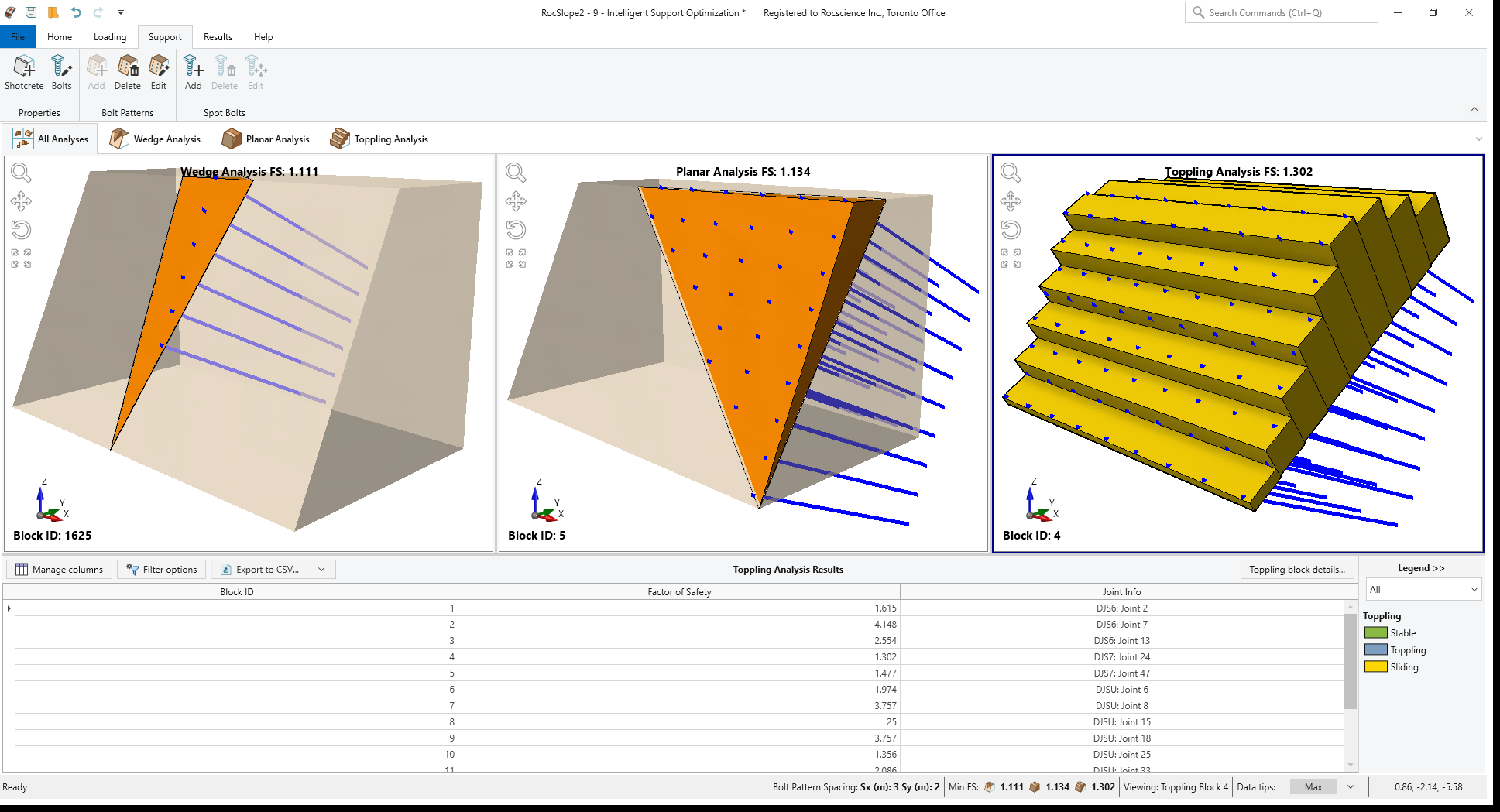
New minimum horizontal and vertical bolt spacing that satisfies the Design Factor of Safety for all analyzed blocks in a rectangle pattern with 1.5 horizontal/vertical spacing ratio is 3m * 2m.
The lowest recalculated Factor of Safety for Wedge Analysis is 1.111, for Planar Analysis is 1.134 and for Toppling Analysis is 1.302.
4.5 Edit Design Factor of Safety
Now let’s change the Design Factor of Safety to re-optimize the pattern spacing for a new target factor of safety.
- Select Home > Analysis > Project Settings
- Go to Analysis and set Design Factor of Safety = 1.5.

Project Settings dialog - Click OK to apply changes and close the dialog.
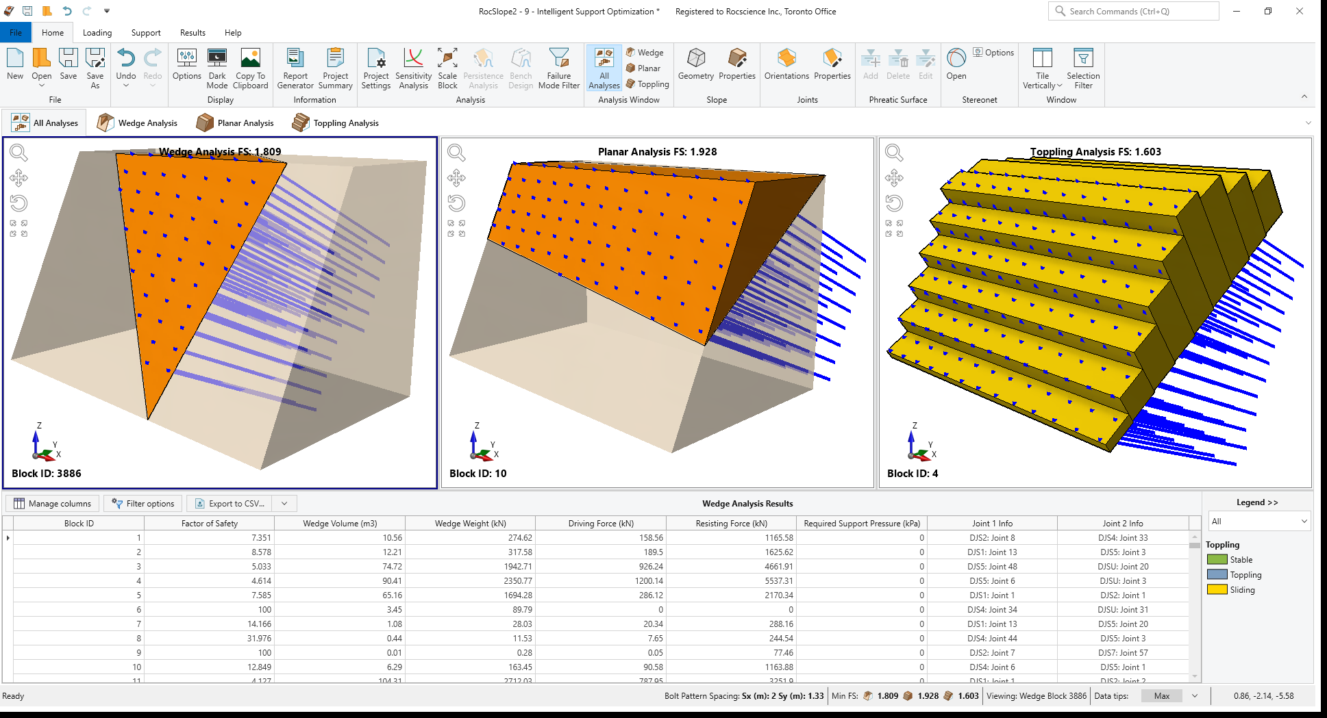
The re-optimized horizontal and vertical bolt spacing that satisfies the modified Design Factor of Safety for all analyzed blocks in a rectangle pattern with 1.5 horizontal/vertical spacing ratio is 2m * 1.33m.
The lowest recalculated Factor of Safety for Wedge Analysis is 1.809, for Planar Analysis is 1.928 and for Toppling Analysis is 1.603.
This concludes the tutorial.