8 - Multiple Joint Sets
1.0 Introduction
This tutorial covers RocSlope2’s ability to add multiple joint sets and import joint sets with their associated joint orientations from clustered joint orientation data in DIPS. In Tutorial 2 – Importing a DIPS File, you learned about importing a list of joints from a DIPS file into a single joint set. In this tutorial, we will focus on adding multiple joint sets and importing joint sets from DIPS file.
Topics Covered in this Tutorial:
- Add Joint Set
- Import Joint Sets from DIPS
- Include / Exclude Joint Set from Analysis
Finished Product:
The finished product of this tutorial can be found in Tutorial 8 Multiple Joint Sets.rocslope2 file, located in the Examples > Tutorials folder in your RocSlope2 installation folder.
2.0 RocSlope2 File
- If you have not already done so, run the RocSlope2 program by double-clicking the RocSlope2 icon in your installation folder or by selecting Programs > Rocscience > RocSlope2 in the Windows Start menu.
When the program starts, a default model is automatically created. If you do NOT see a model on your screen:
- Select File > New

Whenever a new file is created, the default input data forms valid slope geometries for wedge, planar and toppling analysis, as shown in the image below.
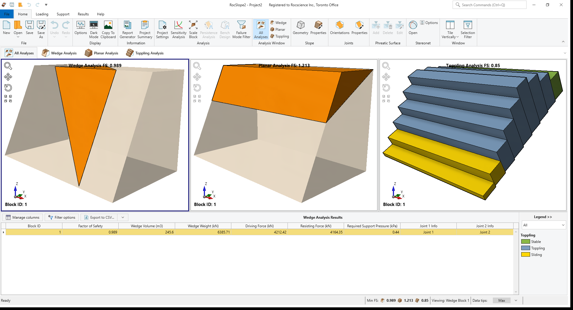
If the RocSlope2 application window is not already maximized, maximize it now so that the full screen is available for viewing the model.
Notice the four-pane, split-screen format of the display, which shows Wedge, Planar and Toppling analysis as well as the results grid pane.
We will not change any default setting for this tutorial.
3.0 Add Joint Set
By default, RocSlope2 considers a single joint set for block formation. Additional sets can be added to allow for the combination of multiple sets of joints with one another.
To add a joint set:
- Select Joints > Orientations

- Click Add
 to add a joint set.
This will add an additional joint set to the joint sets list. Keep in mind that there is no limit in the number of additional joints sets that can be added to the model.
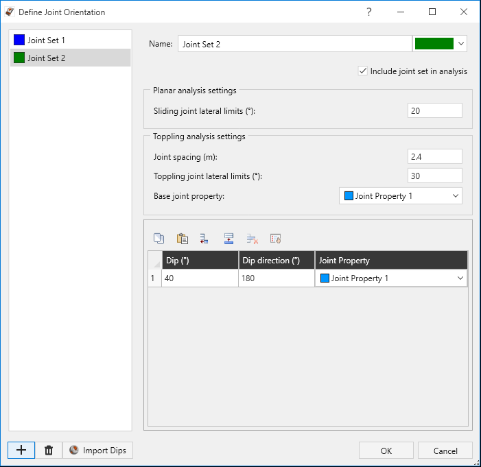
- Select Joint Set 2
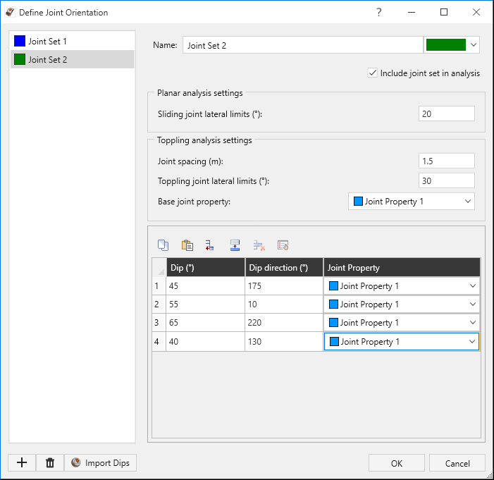
- Change the Joint Spacing under Toppling Analysis Settings to 1.5.
Add three (3) more rows to the Joint Orientations list and edit input data as follows:
Joint Number Dip (°)
Dip Direction (°) Joint Property
1
45
175 Joint Property 1
2
55
10 Joint Property 1
3
65
220 Joint Property 1
4
40
130 Joint Property 1
- Click OK to close the dialog.
Notice that the Wedge, Planar and Toppling analyses are conducted, and Factor of Safety values are computed instantly. For Wedge blocks, a combination of one joint from each set and one joint from other sets are considered. For Planar and Toppling analyses, all joints from all sets which fall within their respective lateral limits are considered.
You should see 6 wedge blocks formed in Wedge Analysis with a lowest FS of 0.7, 2 planar blocks formed in Planar Analysis with a FS of 0.7 and 2 toppling blocks formed in Toppling Analysis with a FS of 0.748.
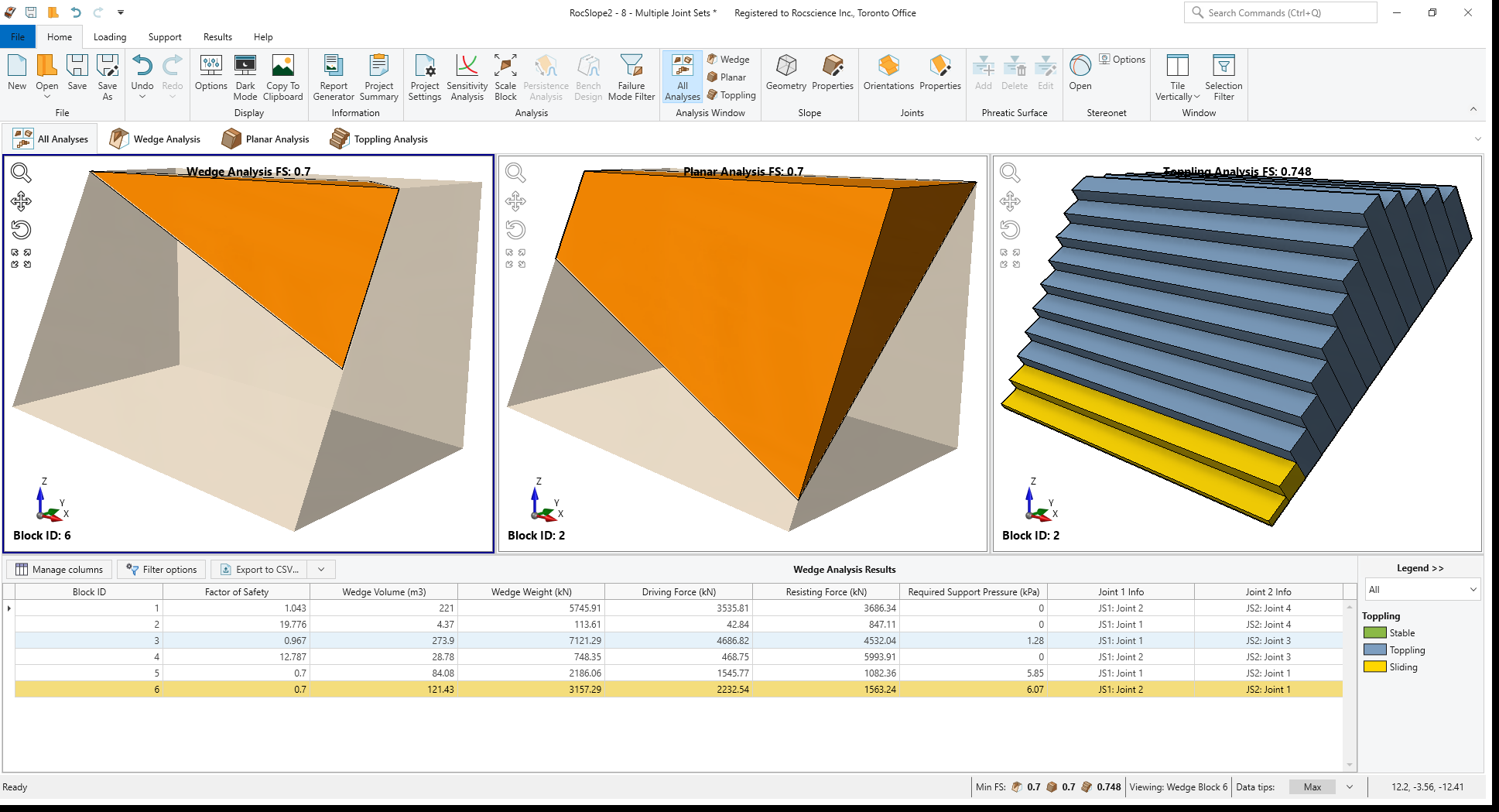
The joint information columns in Results Grid display the joint(s) forming each block.
4.0 Import Joint Sets from DIPS
Joint sets defined in DIPS and their associated joint orientations can be directly imported into RocSlope2.
4.1 DIPS File
A DIPS results file has been provided for importing into RocSlope2 (Tutorial 8.dipsresults).
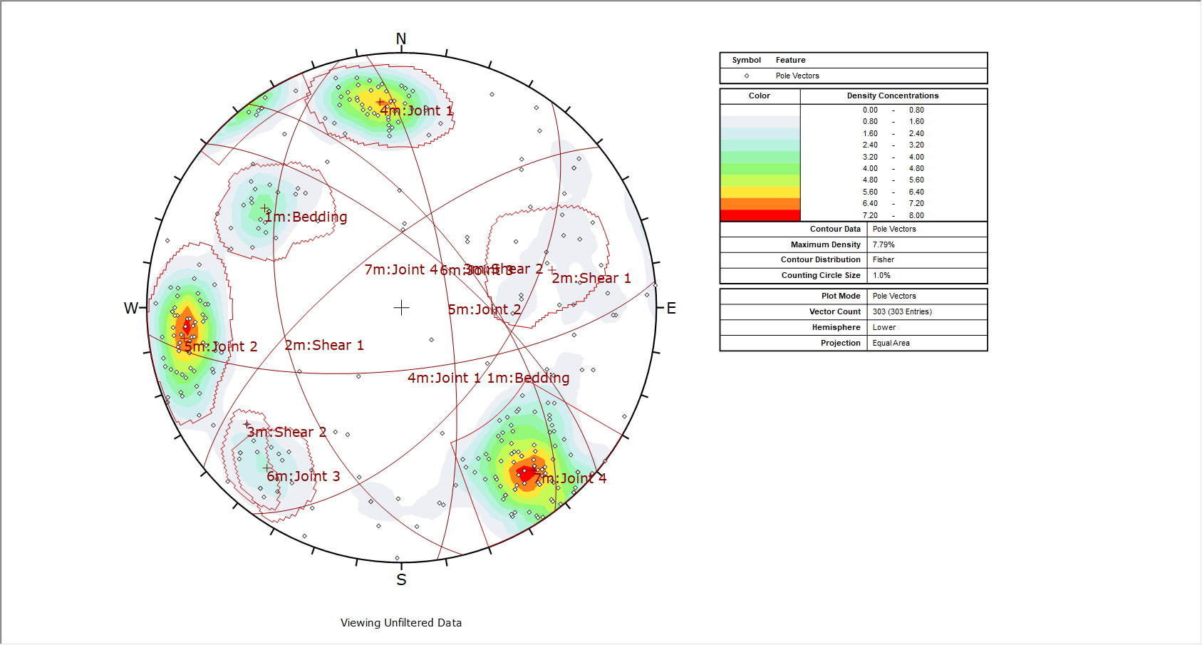
The DIPS file we will use in this tutorial has 7 sets defined and a total of 303 poles (joint orientation measurements). 53 of these poles are not assigned to any joint set in DIPS. The number of joint orientations associated with each set is as follows:
- Joint Set 1 - 22 poles
- Joint Set 2 - 16 poles
- Joint Set 3 - 1 pole
- Joint Set 4 - 46 poles
- Joint Set 5 - 60 poles
- Joint Set 6 - 16 poles
- Joint Set 7 - 89 poles
The Stereonet View of the plotted data in DIPS looks as follows:
4.2 Import Joint Sets from DIPS
- Select Joints > Orientations
- Click the Import DIPS
 button.
 - Select the provided Tutorial 8.dipsresults DIPS file.
- For the Planes to Import option, ensure that Grid Data is selected.
- Ensure that the Preserve joint sets defined in DIPS checkbox is selected in the Import Settings. This will import the joint sets defined in DIPS into RocSlope2 as separate Joint Sets including their respective joint orientations.
- Keep the Overwrite existing joint sets
and Import unassigned joints checkboxes selected.
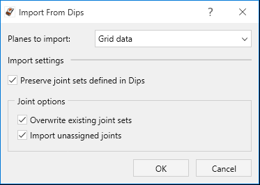
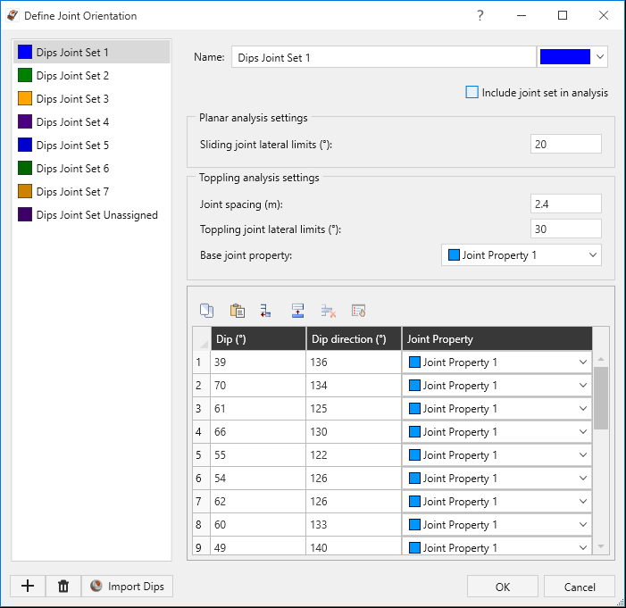
RocSlope2 Import from DIPS dialog - Click OK. Joint Sets and their associated joint orientations are now imported in the dialog. Notice that the joint orientations that don’t belong to any set in DIPS are imported into Unassigned DIPS Joints set.
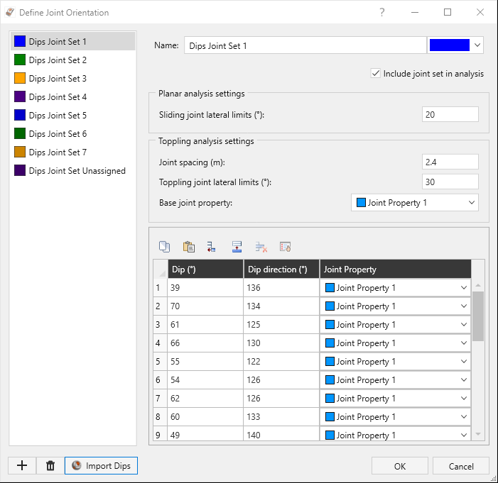
Define Joint Orientation dialog - Leave all other parameters as is. Click OK to apply the changes and close the dialog.
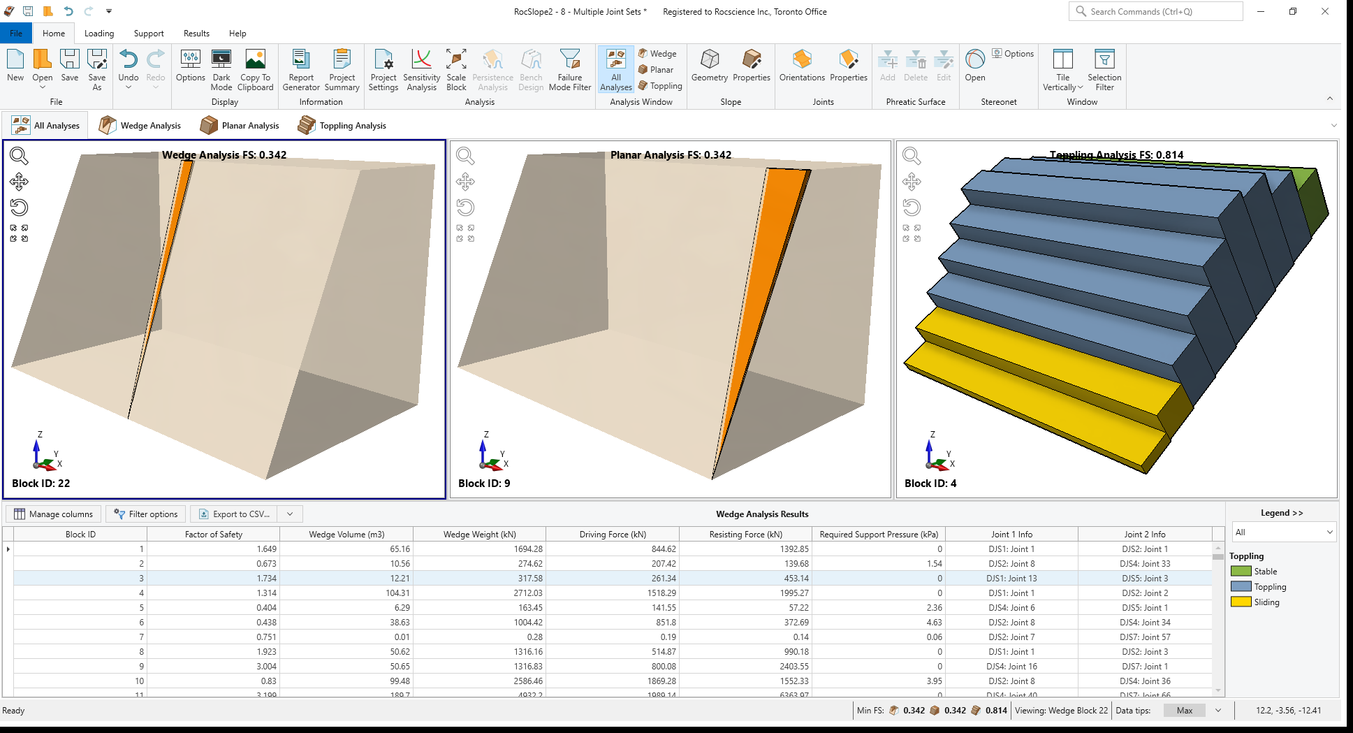
Notice that the Wedge, Planar and Toppling analyses are conducted again, and Factor of Safety values are computed instantly for each block.
You should see the Wedge Analysis with a Factor of Safety of 0.342, Planar Analysis with a Factor of Safety of 0.342 and Toppling Analysis with a Factor of Safety of 0.814.
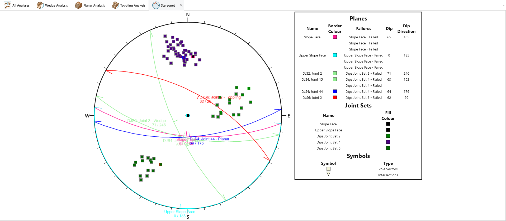
4.3 Stereonet Plot
- Select Stereonet > Open

RocSlope2 Stereonet View - Right-click on anywhere off the stereonet view and turn off the Show Intersections and Show Failures options.
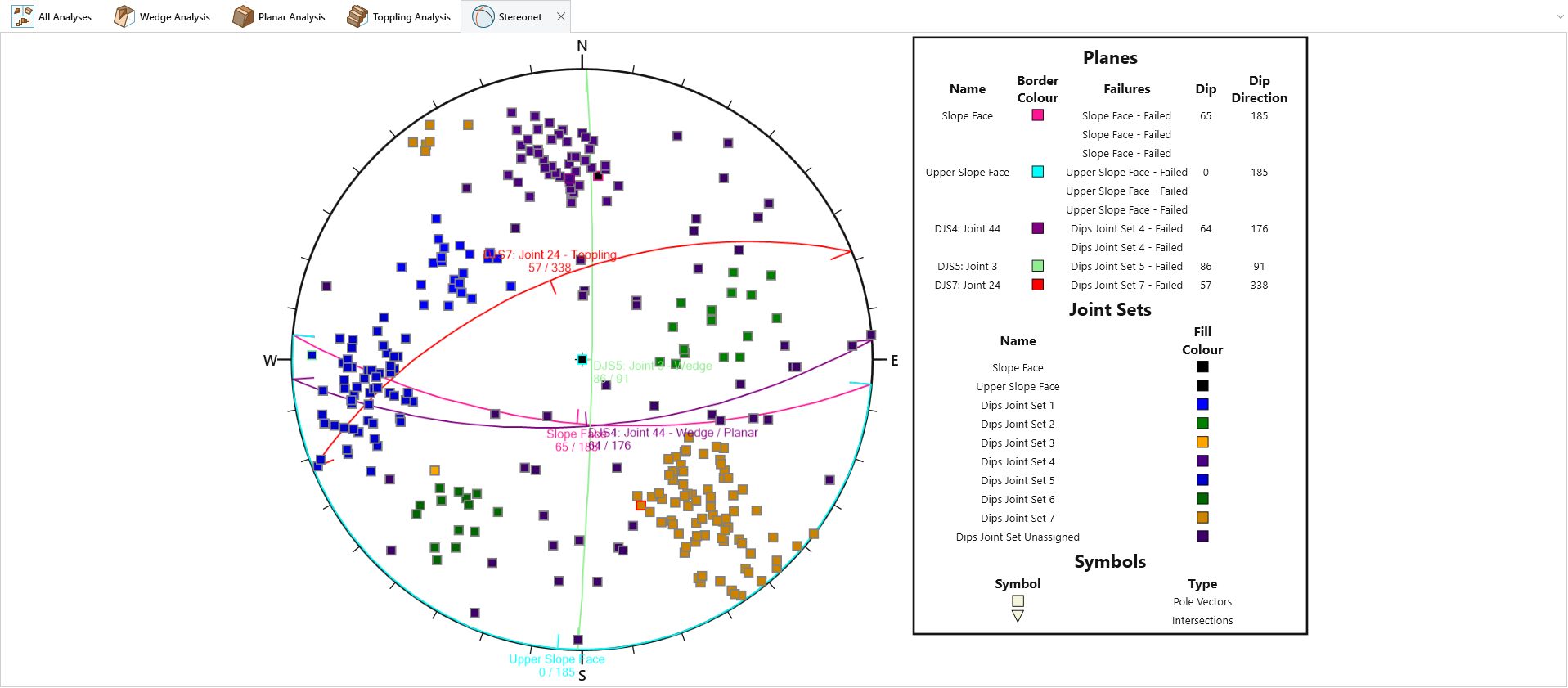
Notice that poles are displayed with fill colours respective to their Joint Set’s colour in the Define Joint Orientation dialog.
To restore the split-screen view in RocSlope2, click on the All Analyses icon  , or click Close
  to close the Stereonet View and return to All Analyses view.
5.0 Include / Exclude Joint Set from Analysis
Joint sets in the Define Joint Orientation dialog can be manually included/excluded from the analysis by toggling the Include joint set in analysis checkbox. If the Include joint set in analysis checkbox is deselected for a joint set, then the joints in that set will not be considered in the Wedge, Planar and Toppling analyses.
- Select Joints > Orientations
- Deselect the Include joint set in analysis
checkbox for the below joints:
- DIPS Joint Set 1
- DIPS Joint Set 3
- DIPS Joint Set 5
- DIPS Joint Set 7
- Unassigned DIPS Joints
- Click OK to apply the changes and close the dialog.
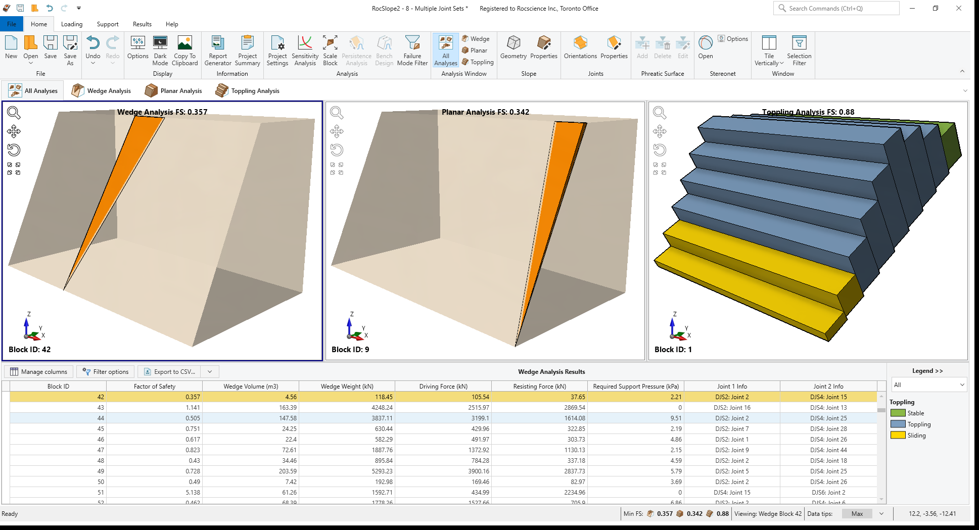
Wedge, Planar and Toppling analyses are performed considering only the joints in DIPS Joint Set 2, DIPS Joint Set 4 and DIPS Joint Set 6. The Factor of Safety values are computed instantly for each block formed.
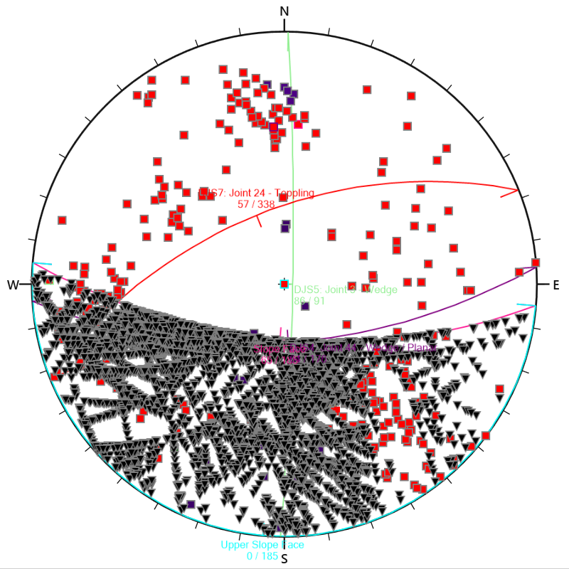
You should see the Wedge Analysis with a Factor of Safety of 0.357, Planar Analysis with a Factor of Safety of 0.342 and Toppling Analysis with a Factor of Safety of 0.880.
If you go to Stereonet View again, the poles of joints excluded from the analysis are also excluded from the stereonet plot, and only the poles included in the analysis are displayed.
This concludes the tutorial. You are now ready for the next tutorial, Tutorial 9 – Intelligent Support Optimization.