4 - Joint Intersecting Tunnel
1.0 Introduction
This tutorial is a simple introductory to help you become familiar with the Joints options as well as basic modelling and data interpretation features of EX3.
Topics Covered in this Tutorial:
- Joints
Finished Product:
The finished product of this tutorial can be found in the Tutorial_04_-_Joint_Intersecting_Tunnel.examine3 data file. All tutorial files installed with EX3 can be accessed by selecting File > Recent Folders > Tutorials Folder from the EX3 main menu.
2.0 Model
When you open EX3 a new project file will automatically be created.
2.1 Project Settings
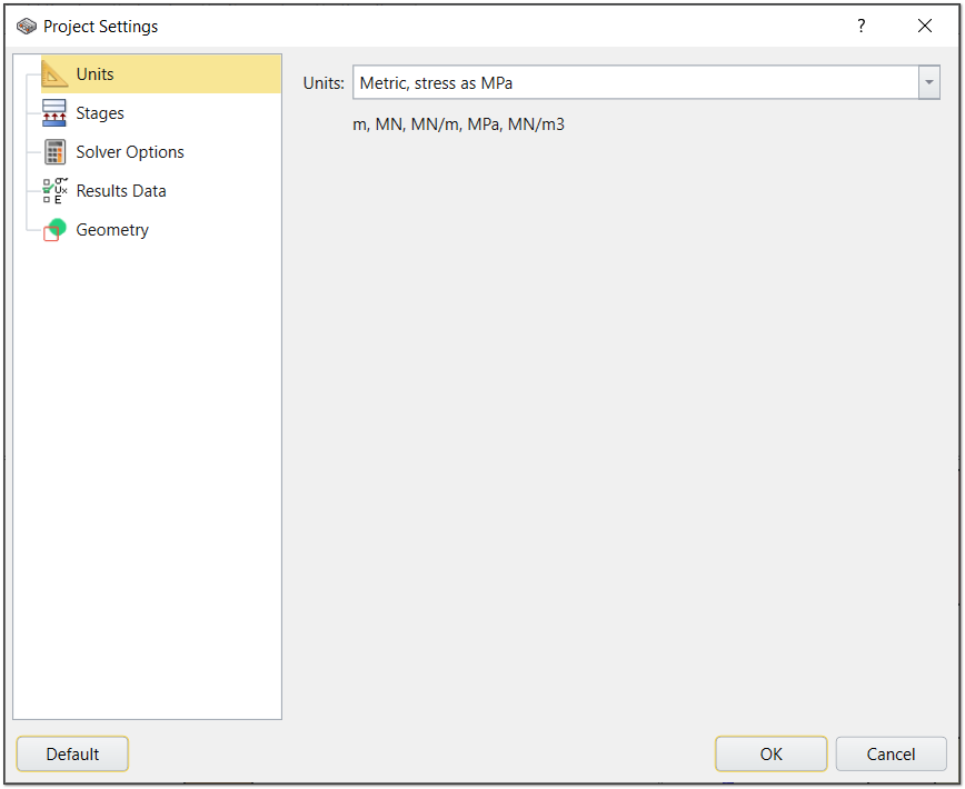
Begin the tutorial by opening the Project Settings. To do so:
- Select Analysis > Project Settings (CTRL + J) from the menu or click on the Project Settings
 icon in the toolbar.
 - Select the Units tab and ensure the units are set to Metric.
2.2 Material Properties
- Select Materials > Define Materials in the menu or click on the Define Materials
 icon in the toolbar.
 - By default, the first material is listed as Host Rock.
- Select the Strength tab and enter Strength Criterion = Mohr Coulomb.
In the Stiffness tab enter:
Material
Young's Modulus (MPa)
Poisson's Ratio
Host Rock
10 000
0.25
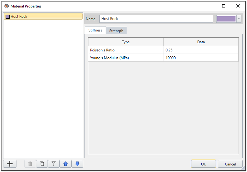
Material Properties - Click OK to close the dialog.
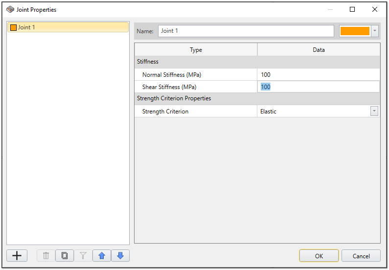
2.3 Joint Properties
- Select Materials > Joints > Joint Properties
 in the menu.
 - Enter the follow properties:
- Normal Stiffness (MPa) = 100
- Shear Stiffness (MPa) = 100
- Strength Criterion = Elastic
3.0 Geometry
3.1 Creating the Tunnels
For this tutorial we will be modeling a tunnel. To begin creating the model:
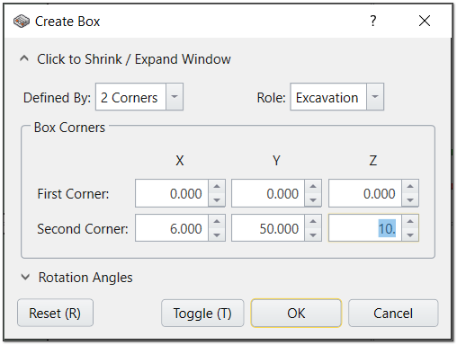
- Select Geometry > 3D Primitive Geometry > Box from the menu or click on the Add 3D Primitives
 icon in the tool bar. This will create the first tunnel.
 - Enter the following properties:
First Corner
- X = 0
- Y = 0
- Z = 0
Second Corner
- X = 6
- Y = 50
- Z = 10
Role = Excavation
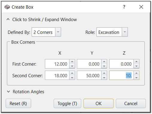
First Corner
- X = 12
- Y = 0
- Z = 0
Second Corner
- X = 18
- Y = 50
- Z = 10
Role = Excavation
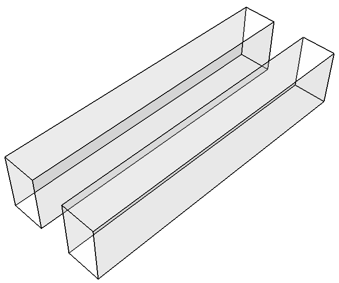
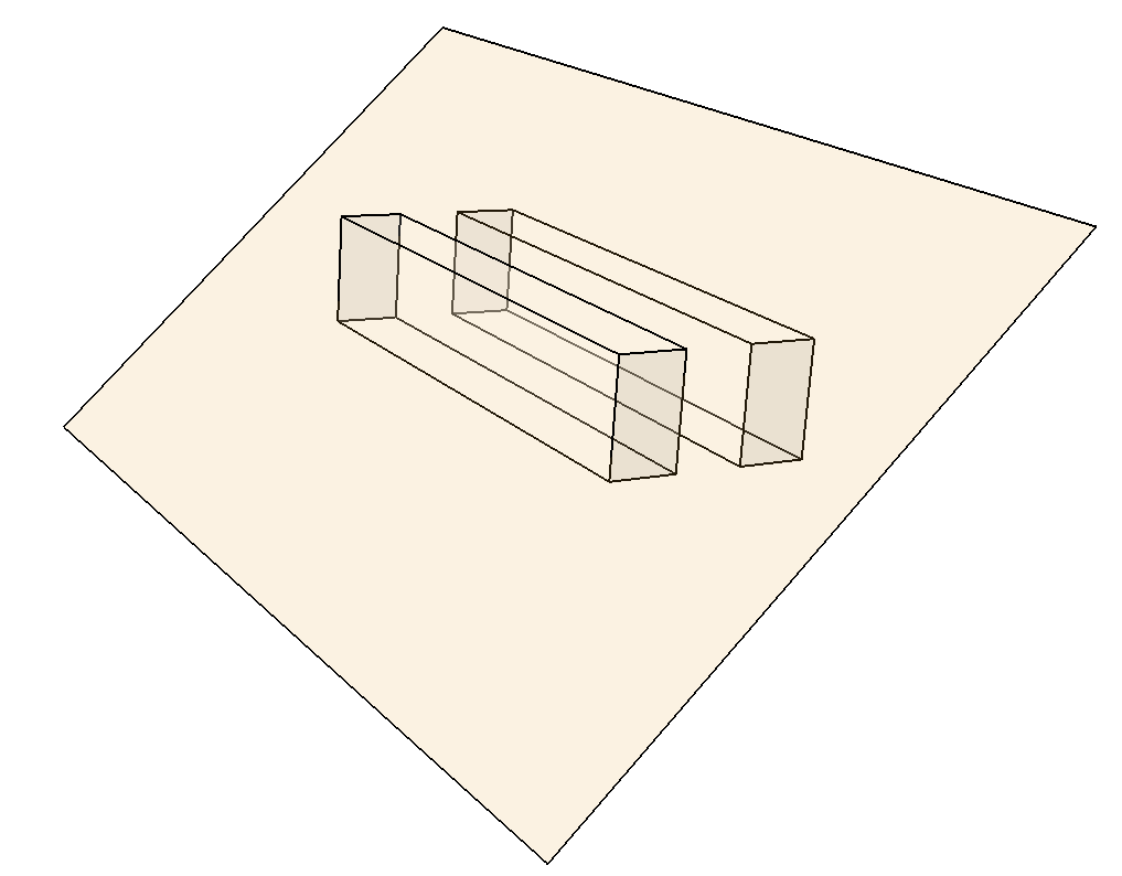
Your model should now look like this:
3.2 Creating the Joint
We will now define the joint plane. To begin:
- Select Geometry>3D Primitive Geometry > Plane from the menu or click on the Add 3D Primitives icon in the tool bar.
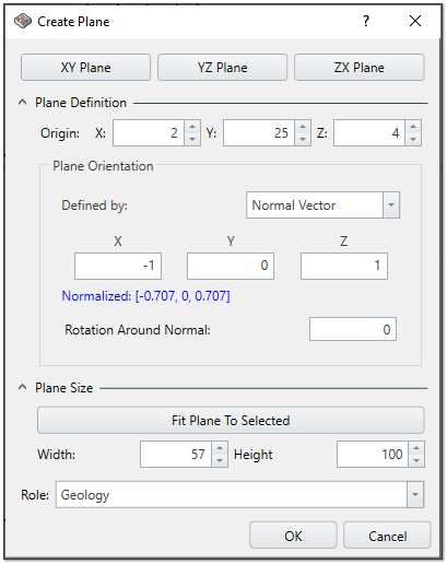
Create Plane - Click on the XY Plane.
- Expand the Plane Definition and Plane Size options and enter the following details:
Origin:
- X = 2
- Y = 25
- Z = 4
Plane Orientation
- Defined by = Normal Vector
- X = -1
- Y = 0
- Z = 1
Plane Size
- Width = 57
- Height = 100
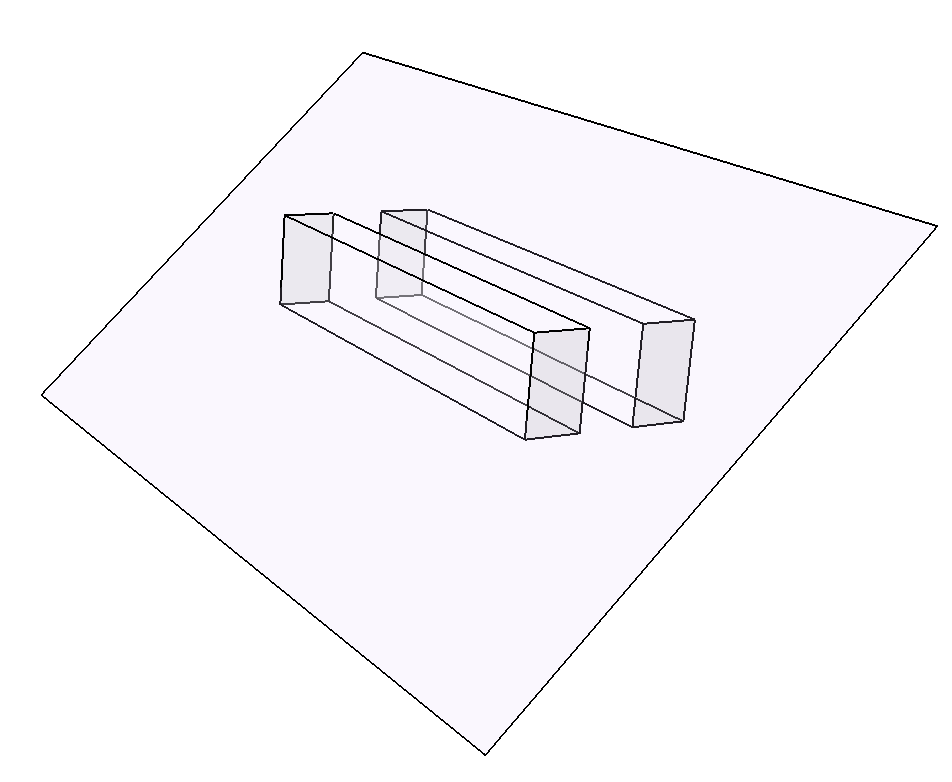
The model should now look as follows:
3.3 Joint Assignment (Set Joints Surface)
- Use your mouse to select the plane defined in the previous section, either by selecting it in the Viewport or in the Visibility Tree.
- Select Materials > Joints > Set Joints Surface
 in the menu. A new dialog will appear.
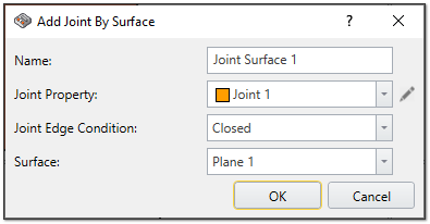
Add Joint by Surface - Leave the default settings as is.
- Click OK to close the dialog.
4.0 Loading
The options in the Loading menu allow you to define all of the various types of loads which can be applied to an EX3 model. For this model, we will be defining the Field Stress.
4.1 Add Field Stress
- Select Loading > Field Stress from the menu or click on the Field Stress
 icon in the tool bar.
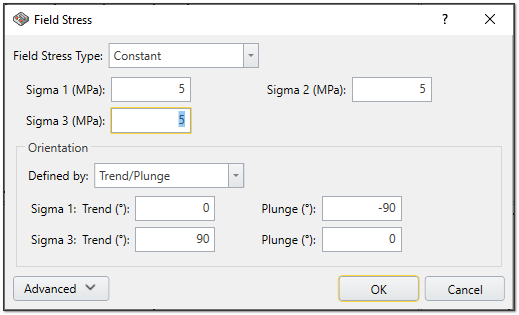
Field Stress - Enter the following properties:
- Field Stress Type = Constant
- Sigma 1 (MPa) = 5
- Sigma 2 (MPa) = 5
- Sigma 3 (MPa) = 5
Orientation
- Defined by = Trend/Plunge
- Sigma 1: Trend =0, Plunge = -90
- Sigma 3: Trend = 90, Plunge = 0
4.2 Divide All Geometry
- Select Geometry > Divide All Geometry from the menu.
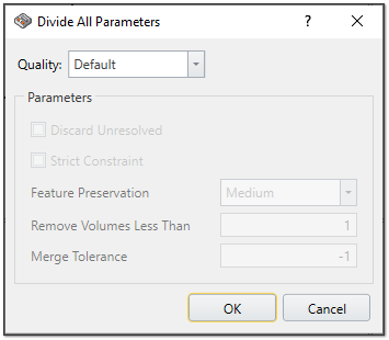
Divide All Parameters - Leave the Quality as Default.
- Click OK.
5.0 Mesh
You can view the Mesh by selecting the Mesh workflow tab.
5.1 Modifying the Mesh
In EX3, you can easily change the density of mesh. To do so:
- Select Mesh > Mesh Settings in the menu or click on the
 Mesh Settings icon in the tool bar.
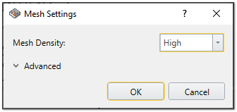
Mesh Settings - Change the Mesh Density to High.
- Click OK.
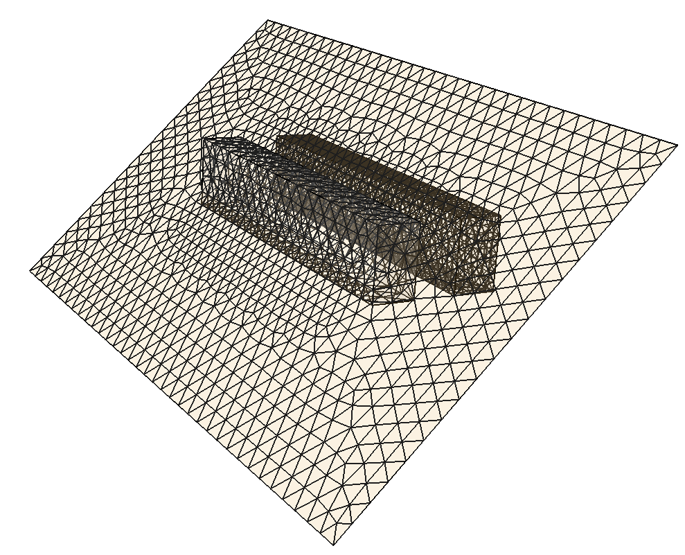
You should now see the following:
6.0 Field Points
To see the results around the excavation, field points should be defined. A user can define as many field points as they need. By moving through each stage of an excavation, the results will update.
Begin by selecting the Field Points workflow tab to see the Field Points tool bar options.
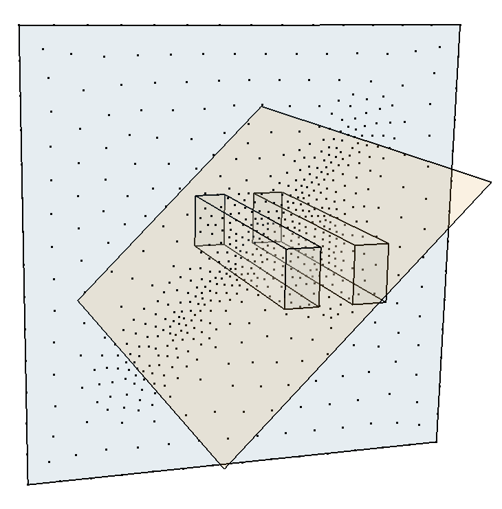
6.1 Add a Field Points Plane
- Select Field Points > Add Field Points Plane from the menu or click on the Field Points Plane
 icon in the tool bar.
 - Select the ZX Plane.
- Set the Plane Size to Width = 80, Height = 80.
- Set the Mesh Density to Medium.
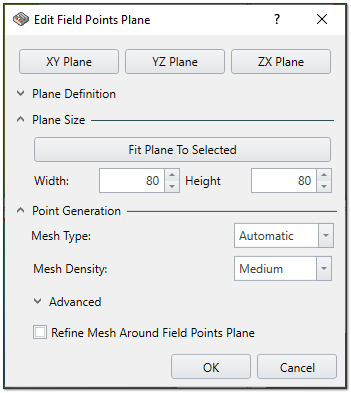
Add Field Points Plane - Click OK.
7.0 Compute
It is now time to compute your results.
- Select Compute > Compute from the menu or go to the Compute tab and then click on the Compute
 icon in the tool bar.
If you have not saved your project, you will be prompted to do so now.
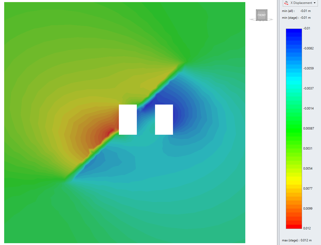
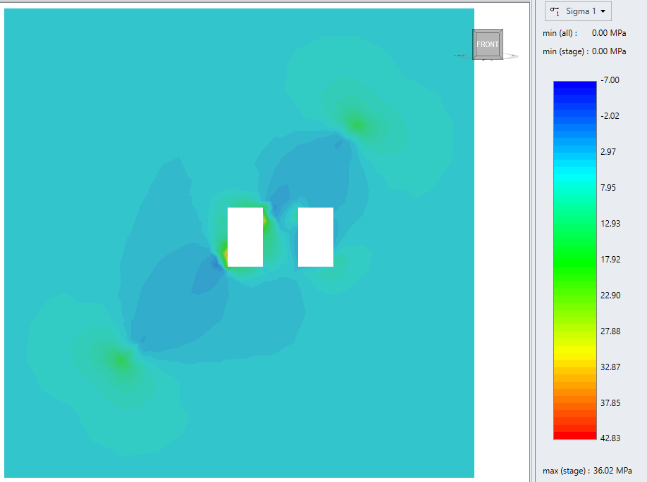
8.0 Results Visualization
After computing, you have several options for viewing your results. You can view Displacement (X, Y, Z, Total Displacement), Stress (Sigma1, Sigma 2, Sigma 3, mean stress, Sx, Sy, Sz, Sxy, Syz, Sxz) and Joint Data (Normal Displacement, Tangential Displacement, Normal Stress, Shear Stress, Slip Tendency, Dilation Tendency). Use the drop down in the contour legend (on the right side of the screen) to make your selection.
To see the results on the Field Point Plane, you can use the Visibility controls (on the left of the screen) to hide the excavation zones. Toggle the eye icons next to an excavation on and off.

This concludes the Joint Intersecting Tunnel tutorial; you may now exit the EX3 program.