3 - Grouping
1.0 Introduction
This tutorial is a simple introductory tutorial that helps you become familiar with the Grouping feature of EX3.
Topics Covered in this Tutorial:
- Segmenter tool
- Grouping
- Isosurfaces
- Stress Ribbons
Finished Product:
The finished product of this tutorial can be found in the Tutorial_03_-_Grouping.examine3 data file. All tutorial files installed with EX3 can be accessed by selecting File > Recent Folders > Tutorials Folder from the EX3 main menu.
2.0 Model Setup
When you open EX3 a new project file will automatically be created.
2.1 Project Settings
Begin the tutorial by opening the Project Settings. To do so:
- Select Analysis > Project Settings (CTRL + J) from the menu or click on the Project Settings
 icon in the toolbar.
 - Select the Units tab and ensure the units are set to Metric, stress as MPa.
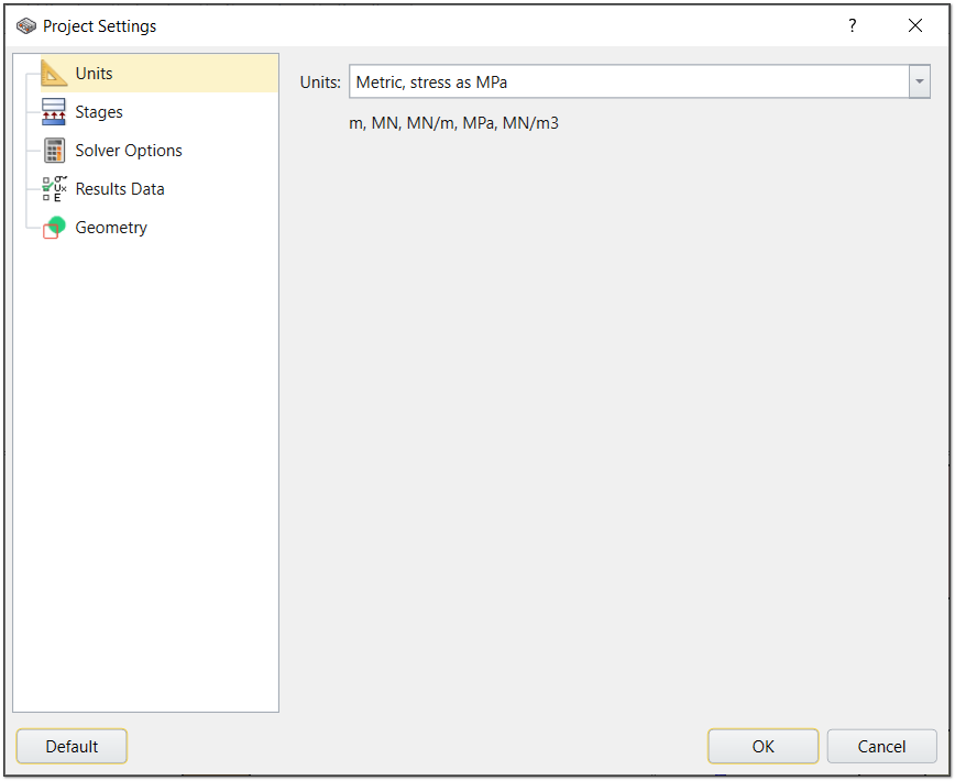
Project Settings - Units - Select the Stages tab and set the number of stages to 5.
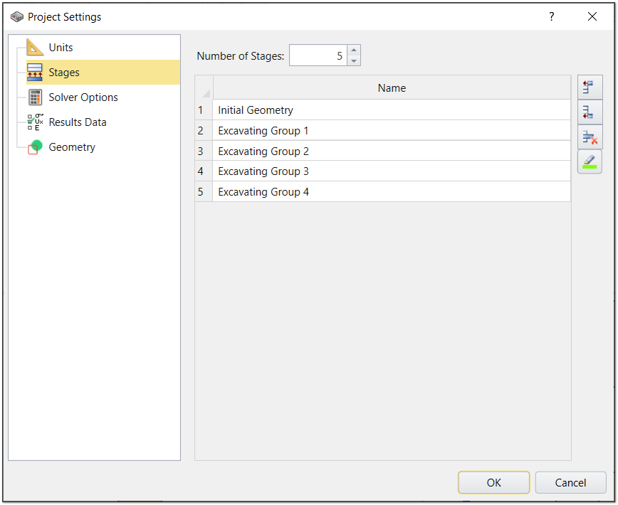
Project Settings - Stages Name the stages as follows:
#
Name
1
Initial Geometry
2
Excavating Group 1
3
Excavating Group 2
4
Excavating Group 3
5
Excavating Group 4
- Click OK to close the dialog.
2.2 Material Properties
- Select Materials > Define Materials in the menu or click on the Define Materials
 icon in the toolbar.
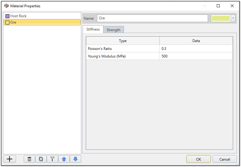
Material properties dialog - By default, the first material is listed as Host Rock. Click on the Add
 button to add two more materials.
 Enter the following properties:
Material Strength tab Stiffness tab Strength Criterion Poisson's Ratio Young's Modulus (MPa) Host Rock Morh Coulomb 0.3 2000 Ore Morh Coulomb 0.3 500 - Click OK to close the dialog.
3.0 Geometry

3.1 Create Boxes
- Select Geometry > 3D Primitive Geometry > Box from the menu or click on the Add 3D Primitives
 icon in the tool bar.
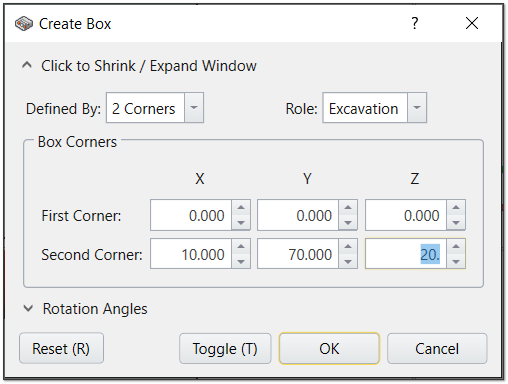
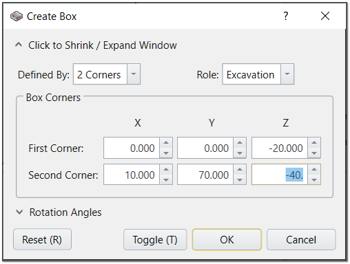
 - Enter the following properties for the First Ore section:
- Defined by = 2 Corners
- Role = Excavation
- First Corner:
- X = 0
- Y = 0
- Z = 0
- Second Corner:
- X = 10
- Y = 70
- Z = 20
- Defined by = 2 Corners
- Role = Excavation
- First Corner:
- X = 0
- Y = 0
- Z = -20
- Second Corner:
- X = 10
- Y = 70
- Z = -40
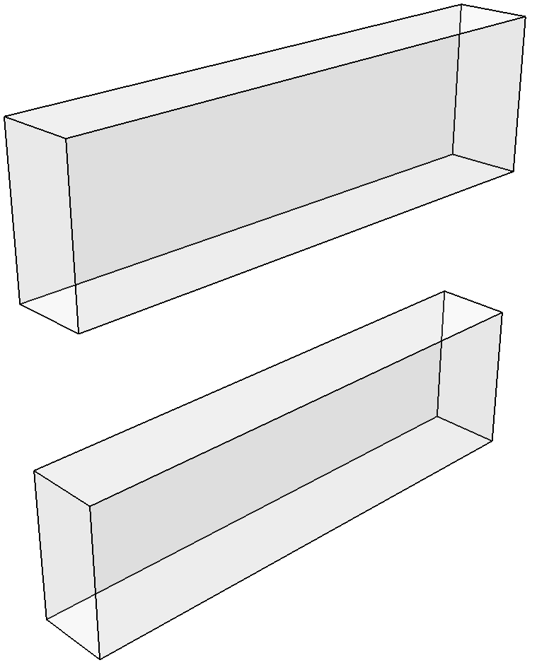
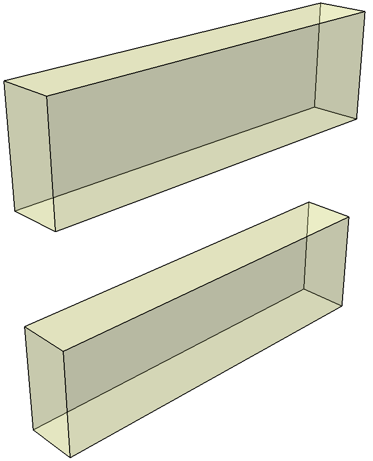
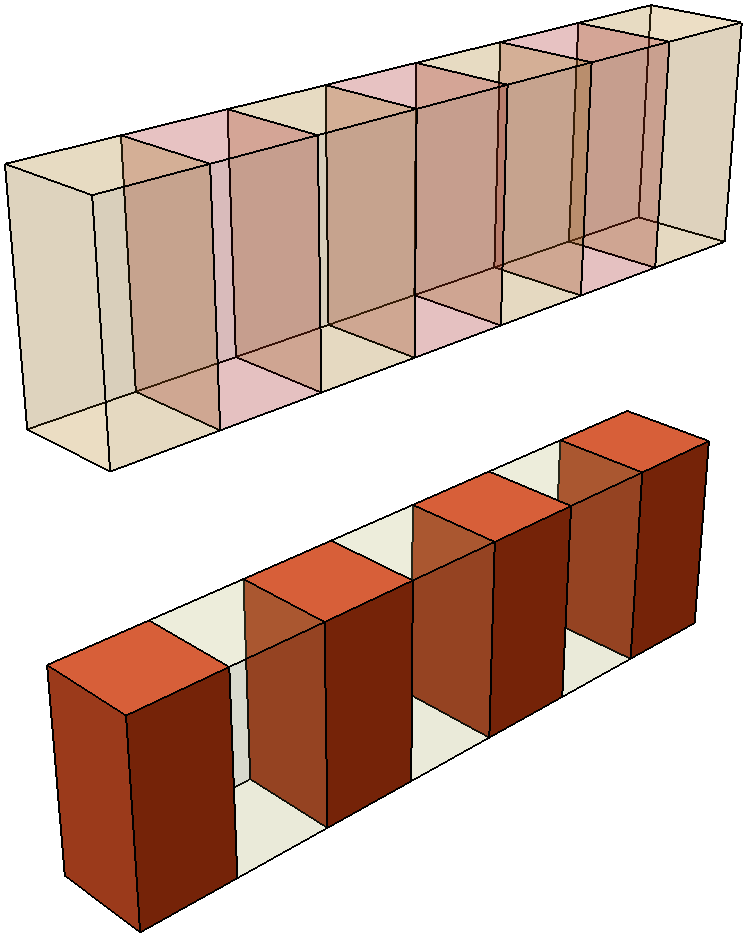
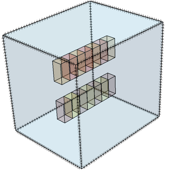
Your model should now look like this:
3.2 Material Assignment
We will now assign the material to each box. This can be done in more than one way.
Option 1: Properties Control
- Use your mouse to select the box you wish to assign a material to. You can either select the Entity using the Visibility Tree or you can click directly on the section of the model.
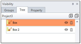
Visibility Tree Notice the Properties pane in the bottom left of the screen. Here you can see the current properties of the selected entity.
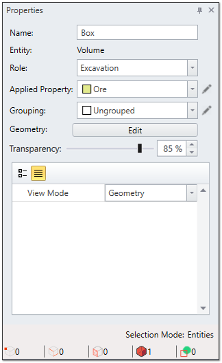
Properties Pane - Change the Applied Property to Ore.
- Repeat this for both boxes.
Option 2: Materials Menu
You can quickly apply a property to an entity using the Assign Material dialog.
- Select Material > Assign Materials in the menu. The dialog will appear.
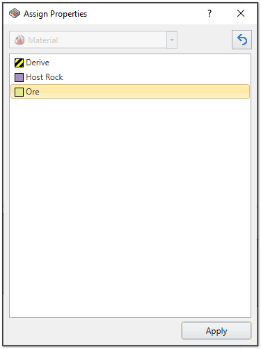
Assign Properties - Select Ore as the material.
- Click on the entity you wish to apply that material to (either by selecting it in the Visibility Tree or by clicking directing on the model).
- Click Apply.
- Repeat this step for both boxes then close the dialog.
3.3 Dividing Boxes Into 7 Pieces – Segmenter Tool
We will now divide the two ore sections in 7 pieces using the Segmenter Tool.
- Begin by selecting one of the boxes.
- Select Geometry > 3D Boolean > Segmenter in the menu or click on the Segmenter
 icon in the tool bar.
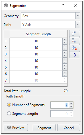
Segmenter - Change the Path to Y Axis.
- Set the Number of Segments to 7.
- Click Segment.
- Repeat the above steps for the second box.
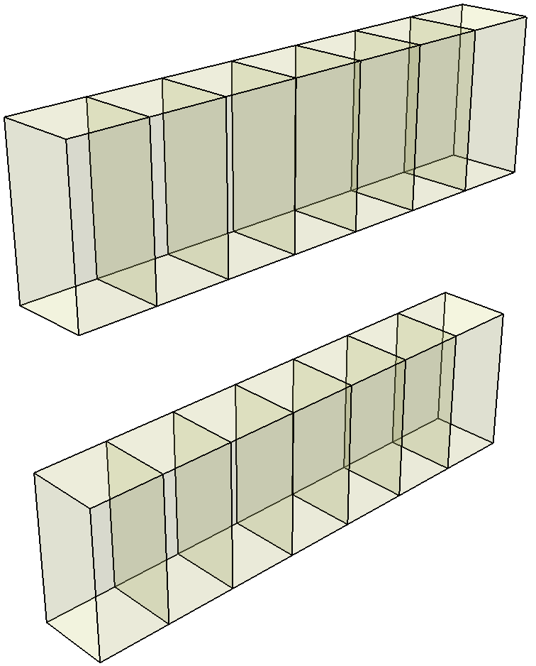
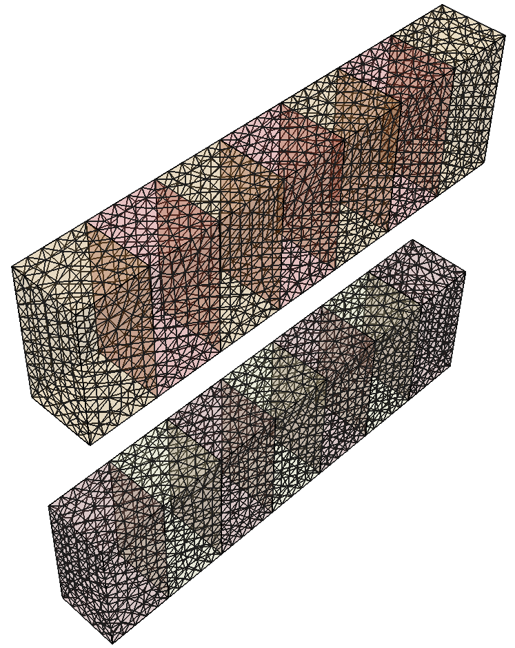
Your model should now look like this:
3.4 Group Assignment
We will now assign the segmented boxes into 4 groups.
- Hold the CTRL key on your keyboard and use your mouse to select the entities you wish to group, either by clicking on the model or selecting them in the Visibility Tree.
- Go to the Properties Pane in bottom left of the screen. The number of Entities selected is displayed at the bottom of the controls.
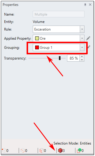
Properties Pane - Select the Group you wish to assign the entities to in the Grouping drop down menu.
- Repeat the above steps for all 4 groups.
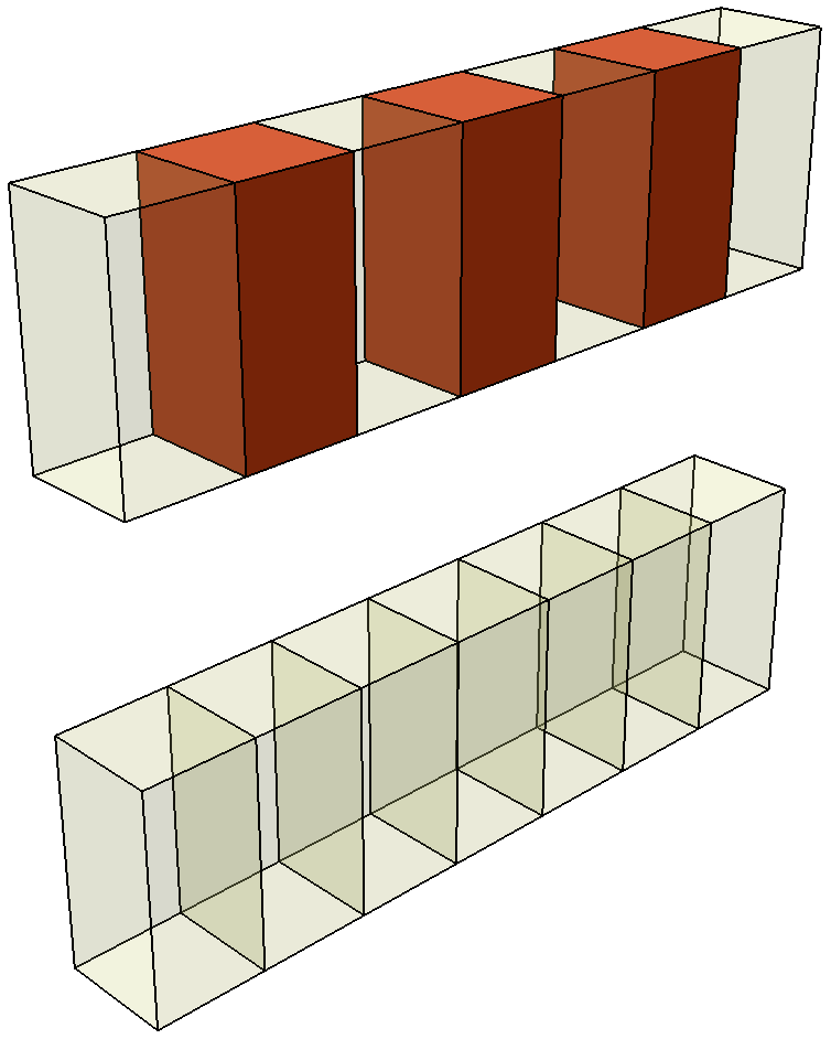
- Assign the 4 groups as follows:
GROUP 1
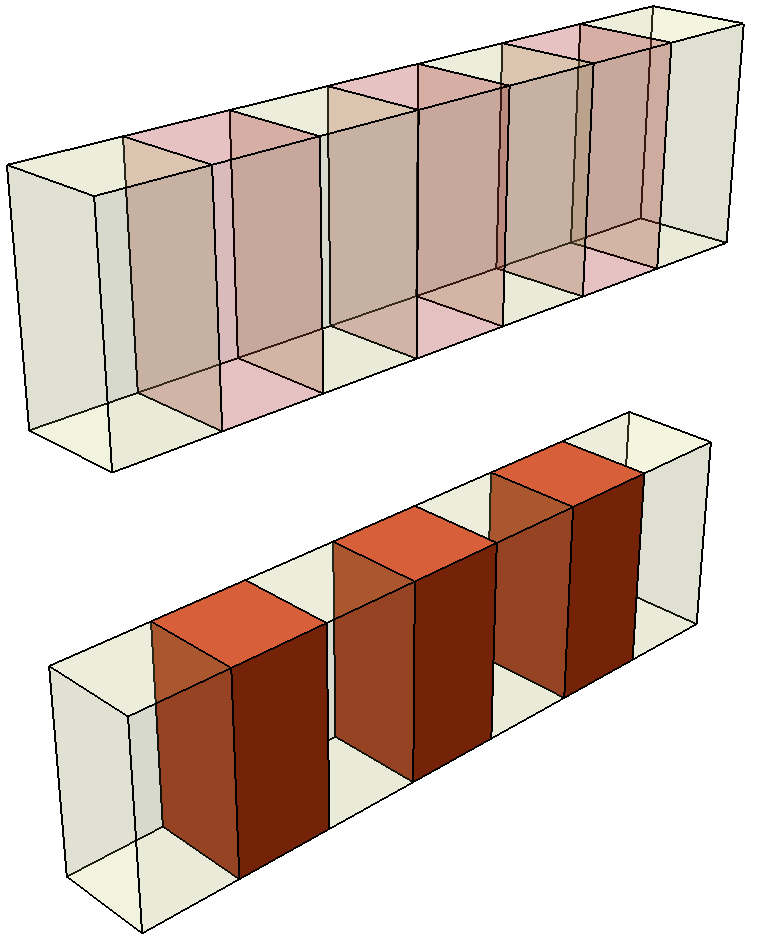
GROUP 2
GROUP 3
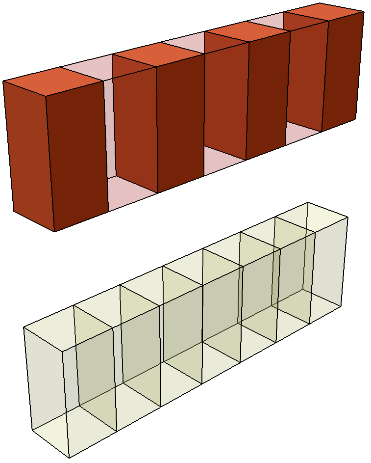
GROUP 4
4.0 Loads

The Loading menu allow you to define all of the various types of loads which can be applied to an EX3 model. For this model, we will be defining Field Stress.
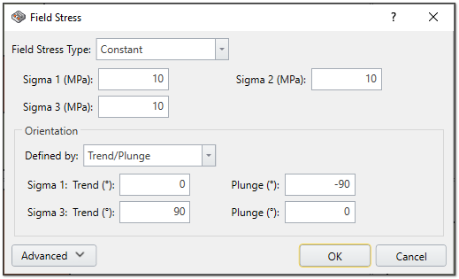
4.1 Adding Stress Loading
- Select Loading > Field Stress from the menu or click on the Field Stress
 icon in the tool bar.
 - Enter the following properties:
- Field Stress Type = Constant
- Sigma 1 (MPa) = 10
- Sigma 2 (MPa) = 10
- Sigma 3 (MPa) = 10
- Orientation
- Defined by = Trend/Plunge
- Sigma 1: Trend =0, Plunge = -90
- Sigma 3: Trend = 90, Plunge = 0
- Defined by = Trend/Plunge
4.2 Divide All Geometry
- Select Geometry > Divide All Geometry from the menu or click on the Divide All
 icon in the tool bar.
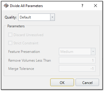
Divide All Parameters - Leave the Quality as Default.
- Click OK.
5.0 Mesh
![]()
5.1 Modifying the Mesh
In EX3, you can easily change the density of mesh. To do so:
- Select Mesh > Mesh Settings in the menu or click on the Mesh Settings
 icon in the tool bar.
 - Change the Mesh Density to High.
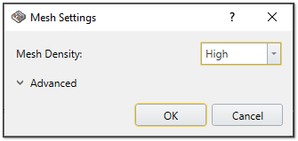
Mesh Settings - Click OK.
You should now see the following:
6.0 Stage Modification
In each stage, the associated group will be excavated. To model the excavation:
- Select Stage 2: Excavating Group 1 in the stages tabs at the bottom of the screen.
- Go to the Visibility Control on the left and select the Groups tab.
- Select Group 1.
- Go the Properties Controls and change the Applied Property of the selected zone to No Material.
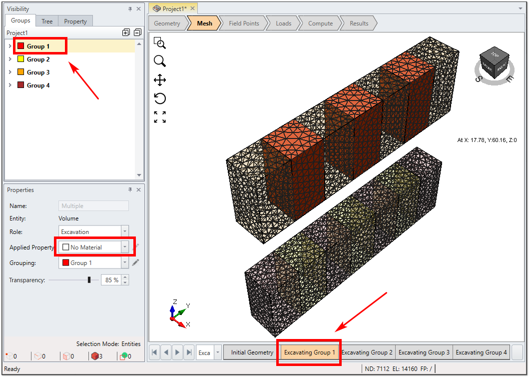
Stages Modification - Repeat this process for each stages as follows:
- Stage 2 (Excavating Group 1) = Group 1 Excavated
- Stage 3 (Excavating Group 2) = Group 2 Excavated
- Stage 4 (Excavating Group 3) = Group 3 Excavated
- Stage 5 (Excavating Group 4) = Group 4 Excavated
7.0 Field Points
To see the results around the excavation, field points should be defined. Users can define as many field points as they need.
7.1 Add Field Points Box
To add a Field Points Box:
- Select Field Points > Add Field Point Box from the menu or click on the Field Point Box
 icon in the toolbar.
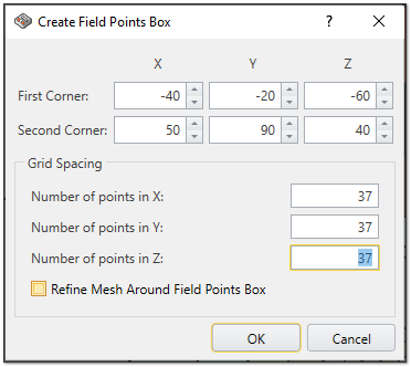
Create Field Points Box Enter the following details:
X
Y
Z
First Corner
-40
-20
-60
Second Corner
50
90
40
Grid Spacing
- Number of points in X = 37
- Number of points in Y = 37
- Number of points in Z = 37
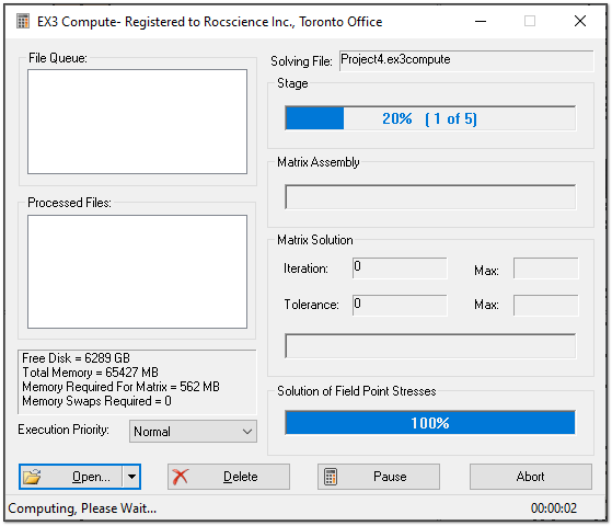
8.0 Compute

It is now time to compute your results.
Select Compute > Compute from the menu or go to the Compute workflow tab and then click on the Compute  icon in the tool bar.
If you have not saved your project, you will be prompted to now.
9.0 Results
![]()
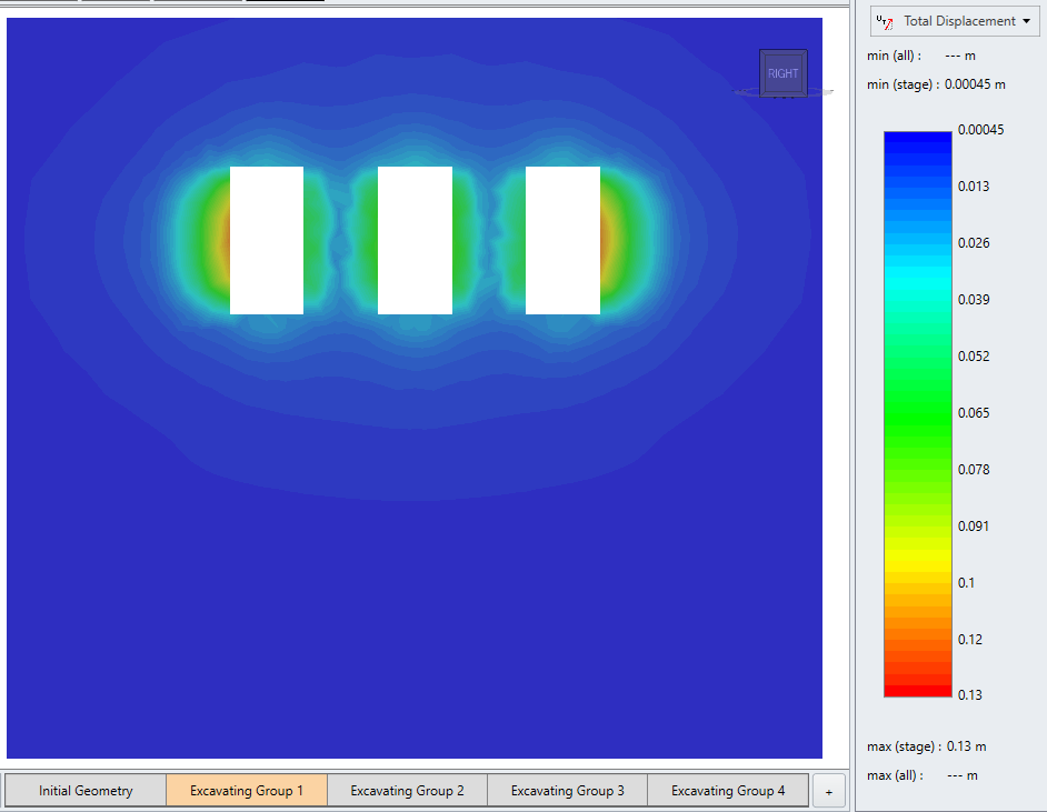
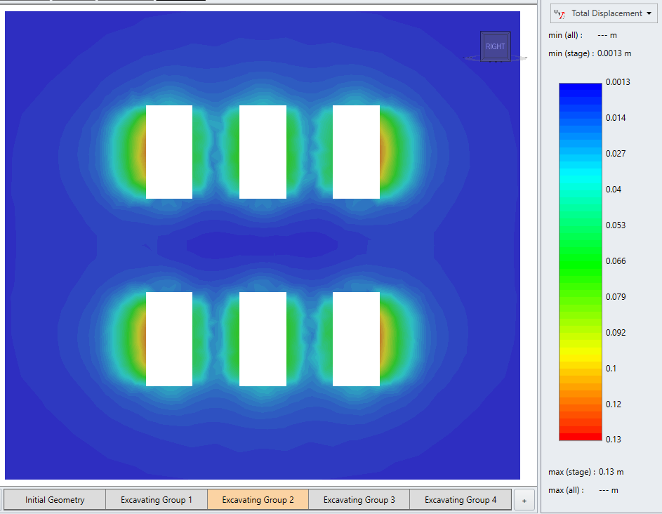
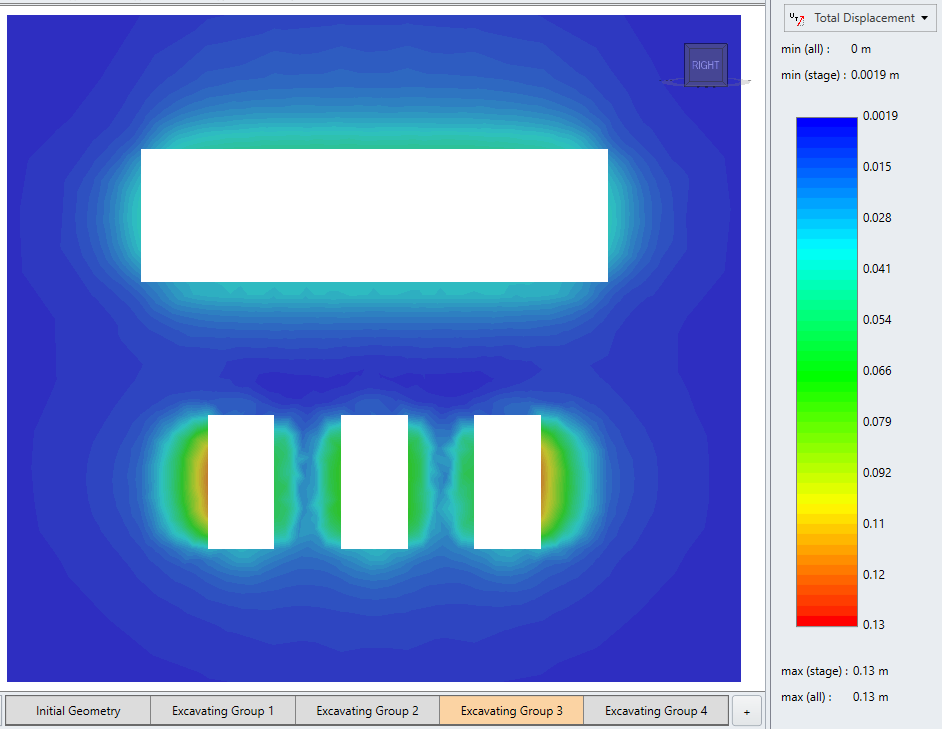
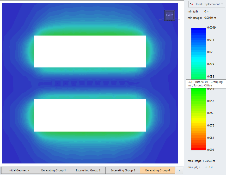
9.1 Results Visualization
After computing, you have several options for viewing your results. You can view Displacement (X, Y, Z, Total Displacement) and Stress (Sigma1, Sigma 2, Sigma 3, mean stress, Sx, Sy, Sz, Sxy, Syz, Sxz). Use the drop down in the contour legend (on the right side of the screen) to make your selection.
To see the results on the Field Points Box, you can use the Visibility controls (on the left of the screen) to hide the ore zones. Toggle the eye icons next to an excavation on and off.
To see the results as shown below:
- Select Interpret > Show Data on Plane > YZ
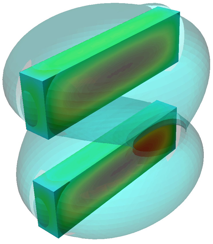
9.2 Isosurfaces
To define the Isosurfaces:
- Select Interpret > Isosurfaces in the menu or click on the Isosurfaces
 icon in the tool bar. A dialog will appear.
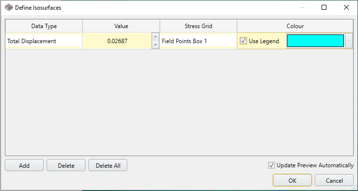
Define Isosurfaces - In the Define Isosurface dialog, users are able to update the Data Type and Value. For this tutorial, enter the following values:
- Date type = Total Displacement
- Value = 0.02687
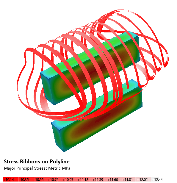
9.3 Stress Ribbon Query
- Select Interpret > Add Stress Ribbon Query in the menu or click on the Add Stress Ribbon Query
 icon in the tool bar. The Draw Polyline controls will appear.
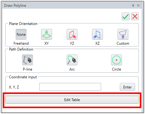
- Click on Edit Table. A new dialog will appear.
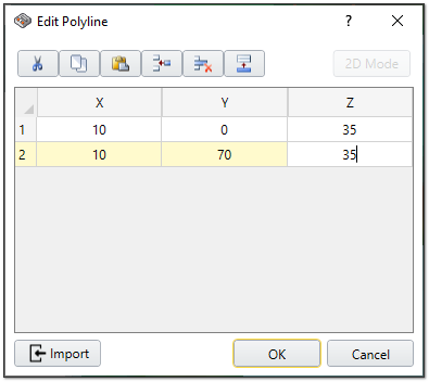
- Click on the Insert Row
 button twice to add 2 rows.
 Enter the follow coordinates for the polyline:
Row #
X
Y
Z
1
10
0
35
2
10
70
35
- Click OK to close the dialog.
- Then click on the green check mark
 icon in the Draw Polyline dialog.
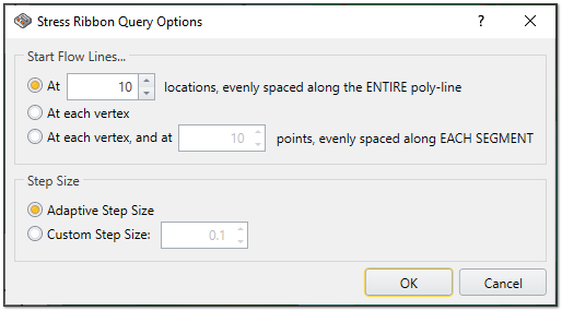
- The Stress Ribbon Query Options will appear.
The Stress Ribbon Query Options allow you to pick the number of locations on the polyline (defined in the previous step), to calculate the stress ribbons. In this case we will leave the default settings.
- Click OK. Stress Ribbons will be calculated at each stage.
This concludes the Grouping tutorial; you may now exit the EX3 program.