4 - Empirical Scaled Span Approach
In Tutorial 01 - Quick Start (Rigid Analysis of Square Pillar), you learned about the Rigid analysis method in CPillar. In Tutorial 02 - Elastic Analysis of Rectangular Roof Beam, you learned about the Elastic analysis method. In Tutorial 03 - Voussoir Analysis of Rectangular Roof Plate, you learned about the Voussoir analysis method. In this tutorial, you will learn about the Scaled Span Approach.
Topics Covered in this Tutorial:
- Critical Limitations of the Scaled Span Empirical Approach
- Model Set-up
- Results Interpretation
- Additional References
Finished Product:
The finished product of this tutorial can be found in the Tutorial 04 Empirical Scaled Span Approach.cpil5 file, located in the Examples > Tutorials folder in your CPillar installation folder.
1.0 Introduction
There are three basic approaches for evaluating the stability of crown pillars or designing new ones:
- Empirical methods;
- Analytical methods; and
- Numerical modeling.
The Scaled Span Approach is an empirical method, separate from the analytical analysis used in the previous CPillar tutorials. The Scaled Span Approach was initially developed for steeply dipping ore body geometries. The method requires the user to estimate crown geometry and assess whether the stope geometry is steep or shallow, in order to apply the most appropriate empirical relationships.
The user must also assess “controlling,” not average, rock mass quality (including assigning the stress and water terms within the estimated Q value). These are important considerations in correct application of the Method. Accordingly the user should familiarize themselves with the following critical limitations before applying the method.
1.1. Critical Limitations
Each of the following critical limitations is described in more detail in the paper “Guidelines for use of the Scaled Span Method for Surface Crown Pillar Stability Assessment.” The links below go to the relevant sections of the paper.
- Revised Scaling Approach - Shallow Stopes (Section 6.1 - pg 14)
- Estimating controlling rock quality (Section 7.1 - pg 22)
- Assessing change in rock quality and failure risk with time (Section 7.2 - pg 23)
- Influence of Structure (Section 7.3 - pg 25)
- Optimizing definition of water and stress terms (Section 7.4 - pg 26)
- Accounting for overburden or lake bodies (Section 7.5 - pg 26)
2.0 Creating a New File
If you have not already done so, run the CPillar program by double-clicking the CPillar icon in your installation folder or by selecting Programs > Rocscience > CPillar > CPillar in the Windows Start menu.
When the program starts, a default model is automatically created. If you do NOT see a model on your screen:
- Select: File > New

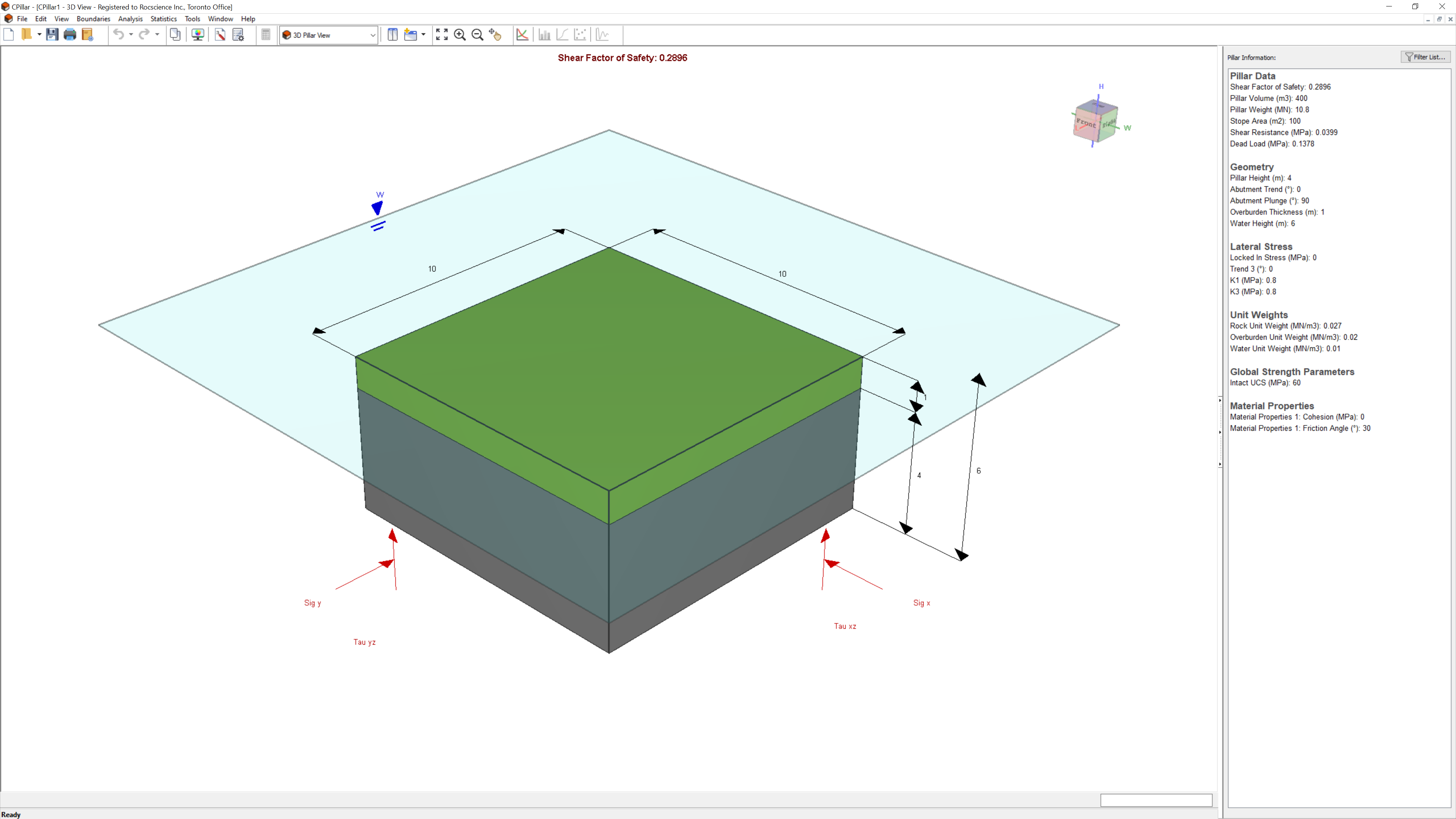
Whenever a new file is created, the default input data forms valid pillar geometry, as shown in the image below.
If the CPillar application window is not already maximized, maximize it now so that the full screen is available for viewing the model. You will have a 3D pillar displayed on the screen in isometric orientation.
3.0 Model Setup
To perform a Scaled Span analysis:
- Select the Empirical Scaled Span Design Method
 option from the Analysis menu.
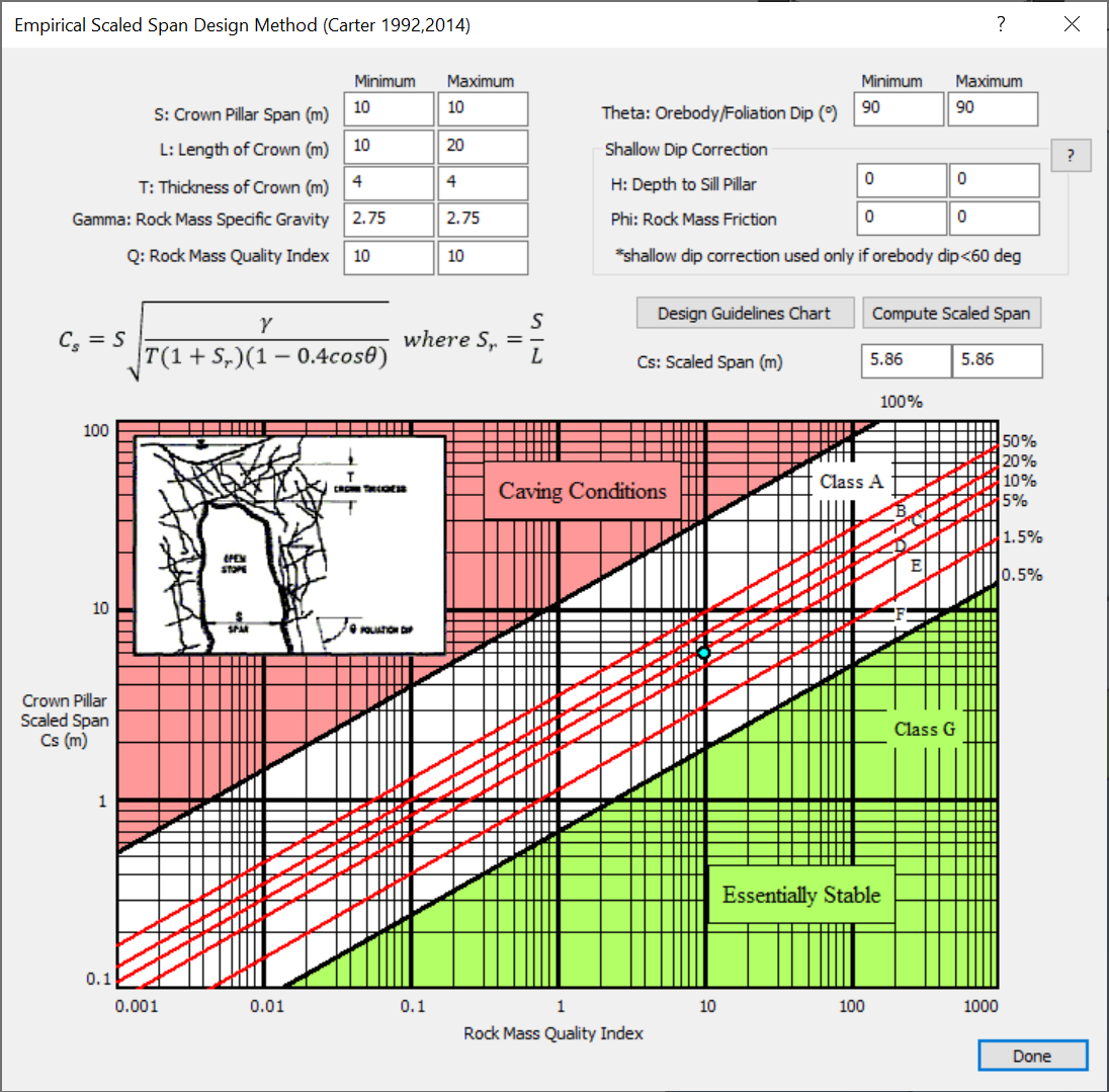
 - The Empirical Scaled Span Design Method dialog will appear:
In order to use the Scaled Span method, we must know the crown pillar geometry and the Rock Mass Quality Index (Q) values of the rock mass. It is important to note here that the Q value must be the “full Q”; the value must include the water and stress terms. This is imperative for considering the water and stress terms in the Scaled Span analysis.
Let's perform a scaled span design for a crown pillar using this dialog. To illustrate the approach, we will first consider average geometry values, but will enter the range of rock quality.
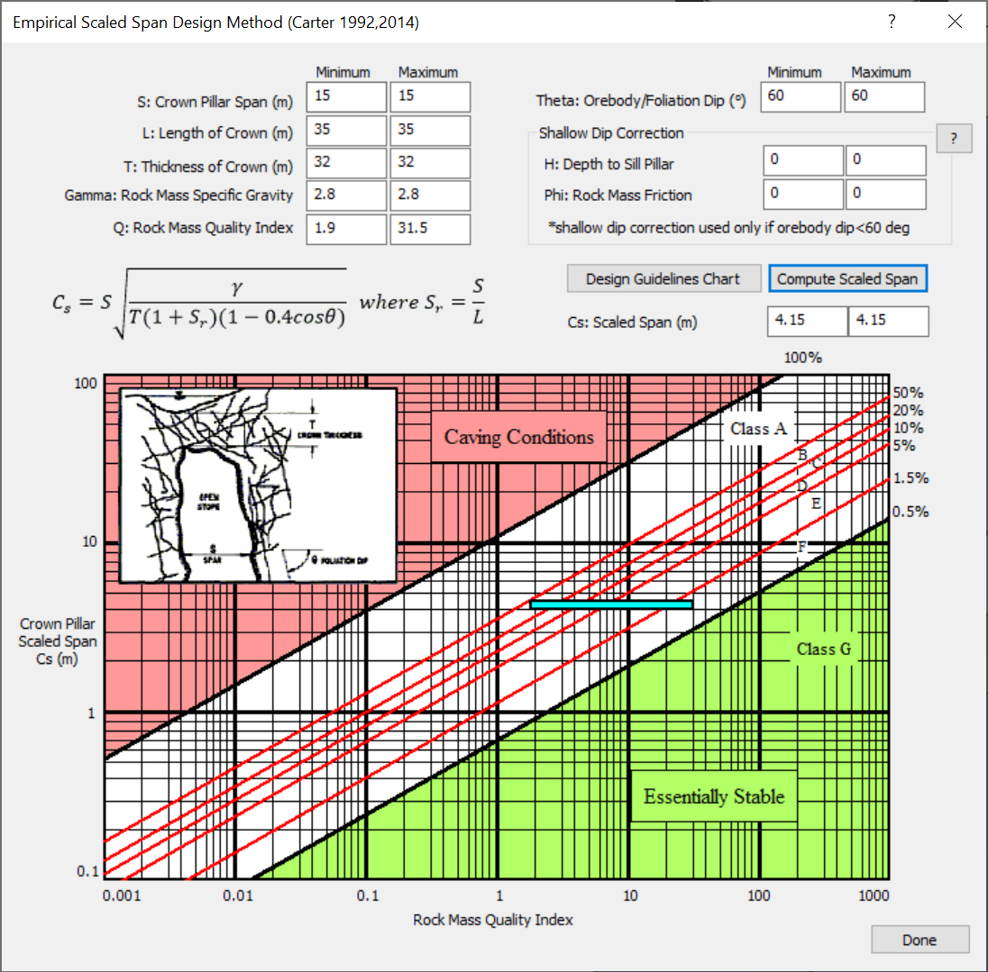
- Enter the crown pillar data in the Empirical Scaled Span Design Method dialog:
- Minimum and Maximum Crown Pillar Span = 15 m
- Minimum and Maximum Length of Crown = 35 m
- Minimum and Maximum Thickness of Crown = 32 m
- Minimum and Maximum Rock Mass Specific Gravity = 2.8
- Minimum Rock Mass Quality Index = 1.9
- Maximum Rock Mass Quality Index = 31.5
- Minimum and Maximum Orebody/Foliation Dip = 60 deg
- Select Compute Scaled Span button.
Our Crown Pillar Scaled Span (Cs) value has been calculated and an area has been highlighted on the chart. It is calculated using the equation shown in the dialog. This value characterizes the geometry of the crown pillar. The equation evolved from the simple “Rule-of-Thumb” methods of crown pillar evaluation. It was developed as a more accurate relationship which could be properly scaled to rock mass quality.
Once again it should be noted that Cs only characterizes the geometry of the pillar, not taking into account the influence of clamping stresses or groundwater. This is why the full Q with water and stress terms must be used in the analysis.
4.0 Analysis Results
We can now interpret the results on the chart. The calculated Cs = 4.15 value is used to select the y coordinate of the highlighted box. The width of the box is defined by the Qmin and Qmax values, shown on the x-axis. Our pillar is placed in the range of Class B through Class F (noted in the white area), with a Probability of Failure ranging from ~1% to ~50% (red lines).
In the Empirical Scaled Span Design Method dialog:
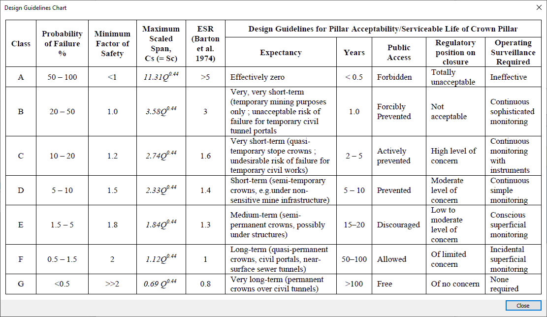
- Click on the Design Guidelines Chart button
 to see what this information means.
As expected ranges B through F constitute a Probability of Failure between 0.5% and 50%. In this case we will take the worst case scenario, Class B. This indicates that the life expectancy of the pillar is very, very short-term (~1 year), and that public access is “forcibly prevented.” This would be acceptable in a mining block where surface risks can be mitigated perhaps by incorporating “continuous sophisticated monitoring” if critical surface infrastructure is sited over the crown area, but would not be acceptable for “mine closure” handover.
The Critical Scaled Span value for Probability of Failure = 50% at Factor of Safety = 1.0 is defined as:
Sc = 3.58Q^0.44.
For this example, we can take the Qmin value =1.9, and substitute in the above expression to estimate the Critical Scaled Span:
Sc = 3.58(1.9)^0.44 = 4.75.
This value indicates the maximum stable scaled span at Probability of Failure = 50% (Factor of Safety = 1.0) for this rock mass quality.
While it is preferred that results of Scaled Span assessments be presented in terms of Probability of Failure, if desired, a crude estimate of the Factor of Safety can be approximated (Carter et. al., 2008) from the following expression:

5.0 References
More information about the Scaled Span empirical method can be found in the paper “Guidelines for use of the Scaled Span Method for Surface Crown Pillar Stability Assessment.” Additional information can be found in about the CPillar Empirical Scaled Span Design Method.
Carter, T.G. (2014). Guidelines for use of the Scaled Span Method for Surface Crown Pillar Stability Assessment. Proc. 1st International Conference on Applied Empirical Design Methods in Mining, Lima-Perú, 9-11th June, 34pp
Carter, T.G., Cottrell, B. E., Carvalho, J.L. and Steed, C.M. (2008) Logistic Regression improvements to the Scaled Span Method for dimensioning Surface Crown Pillars over Civil or Mining Openings. Proc. 42nd US Rock Mechanics Symposium and 2nd Can-US Rock Symp. San Francisco. Paper 08-282 10pp
This concludes the tutorial. You are now ready for the next tutorial, Tutorial 05 - Rigid Analysis of a Polygonal Pillar.


