The Power of Simplicity: How Elastic Models can be Effectively Used in 3D Finite Element Analysis
Dr. Reginald Hammah wrote a great article titled "Who Said Elastic Models are not Useful?” Leveraging his years of practical experience in the field, he outlined the differences between elastic and plastic material behaviour and identified some important considerations as to when elastic models could and should be used. Spoiler alert: it’s more often than you’d think.
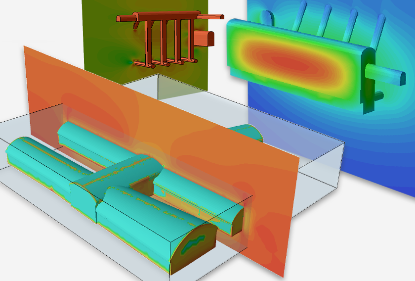
The case study below highlights the effective use of an elastic model in RS3 to efficiently model the interaction between timber crane mats, backfilled granular material, and an existing box culvert.
Application of RS3 for Crane Mat Analysis
Grounded Engineering Inc. conducted an evaluation for a proposed industrial warehouse complex in Milton, Ontario. The assessment focused on the use of timber crane mats to achieve a uniform distribution of crane loading and examined the additional stresses on an existing box culvert. The engineering team utilized 3D Finite Element Modeling (FEM) using RS3, to simulate the effects of crane loading on the mats and the underlying box culvert.

Project Considerations
A number of considerations from the contractor and client were incorporated into the analysis:
- A uniform 950mm cover thickness above the box culvert was considered.
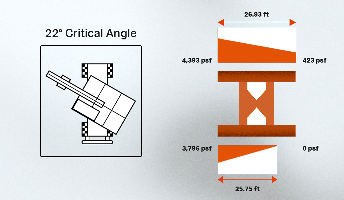
- Crane analysis confirms maximum crawler crane load of 454,000 lbs at 22-degree critical boom angle and 497,000 lbs with a precast panel load at 23-degree critical boom angle.
- The contractor specified that additional vertical effective stresses imposed on the box culvert due to crane loading must not exceed 70 kPa.
- Client instructed Grounded to analyze load case where crane tracks were parallel to the box culvert.
- The culvert, given its size/thickness relative to the applied load and timber mat, was modelled as a continuum with elastic properties of uncracked concrete.
Key Steps in the RS3 Model
- Initial Stage: The existing subgrade, including the box culvert, is modeled as a single layer of soil across the entire model.
- Mat Installation: A liner representing the timber crane mats is installed in the model.
- Crane Loading: A distributed load representing the crane crowd pressure is applied on the surface, simulating the actual loading conditions.
Timber Mat and Soil Parameters
The timber mats were modeled as two 150’x8’ liner elements, with stiffness parameters derived from static load tests. The crane mat's effective stiffness was considered, reflecting its composite nature. Soil parameters, including Young's modulus, were defined based on the contractors’ suggestions, and a sensitivity analysis was performed to ensure the robustness of the results.
Note: Grounded also performed sensitivity analysis modelling the soil as uniform elastic-plastic material with the same soil parameters and found no significant differences.
Culvert Modelling
The box culvert is modeled as a continuum object with linear elastic material properties based on geometry provided in the contractor’s report. The concrete stiffness parameters are derived following CSA A23.3 standards, assuming a compressive strength of 30 MPa.
Critical Areas of Analysis
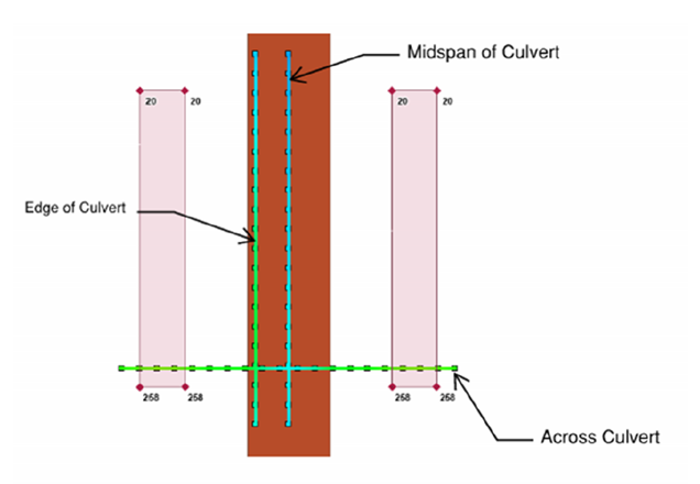
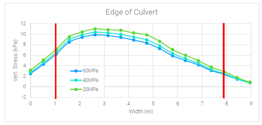
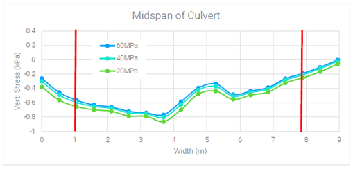
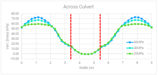
Three critical areas were identified for detailed analysis: the edge of the culvert, midspan of the culvert, and along the crawler track. These areas were chosen to assess the impact of crane loading on the structural integrity and ground bearing pressures.
Model Validation and Results
Before conducting the detailed analysis, the model was validated by comparing the crane load distribution profile between RS3 and the analytical Boussinesq equation.
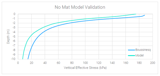
The validated model was then modified to include the crane mat and box culvert.
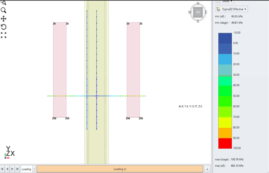
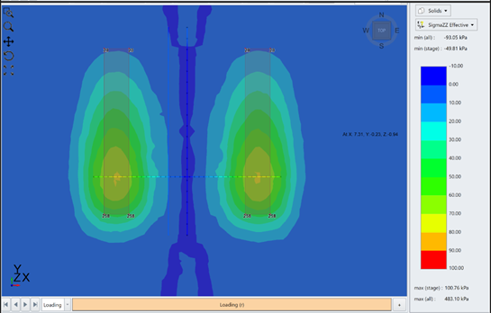
All the following graphs have been overlaid with the location of the edge of the crawler tracks (solid red) and the culvert (dashed red) for better illustration. The results from the analysis below show that the additional vertical effective stress on top of the box culvert remains below 70 kPA for all the backfilled material conditions and ultimately satisfied the project requirements.
The recommendation was to lay the mats perpendicular to the track’s longitudinal axis as shown in Figure X. An additional recommendation was to include a layer of compacted soil to be provided along the edge of the mat area to prevent slippage.
Conclusion
The application of RS3 in this engineering evaluation showcases the power of finite element analysis in optimizing the design of timber crane mats and help engineers in their decision making. Utilizing an elastic model, engineers gained valuable insights into the structural response of the mats, ensuring they effectively distribute crane loading while staying within the elastic limit.
In conclusion, the synergy between advanced finite element analysis and the practical engineering insights provided by Grounded Engineering enabled a thorough evaluation of crane mat applications in the proposed industrial warehouse complex. This approach ensured the structural integrity of the system, meeting both safety and efficiency criteria of the construction project.