Introducing Stope Section View in CPillar
by Angela Li
CPillar is a quick and easy-to-use software for the analysis of surface or underground crown pillars and laminated roof beds. This limit-equilibrium program is capable of deploying three different analysis methods: Rigid Plug, Elastic Plate, and Voussoir Beam.
The latest features and improvements in CPillar include the 2D Stope Section view, along with several import and annotative tools for easier definition of polygonal pillar geometry, and abutment material assignment.
Stope Section View
We previously introduced Rigid Analysis for Polygonal Pillars, which allowed for users to define any shape of pillar via a coordinate table. This was time-consuming and difficult to visualize the geometry as it lacked a specialized 2D view with interactive graphical components.
Introducing Stope Section View
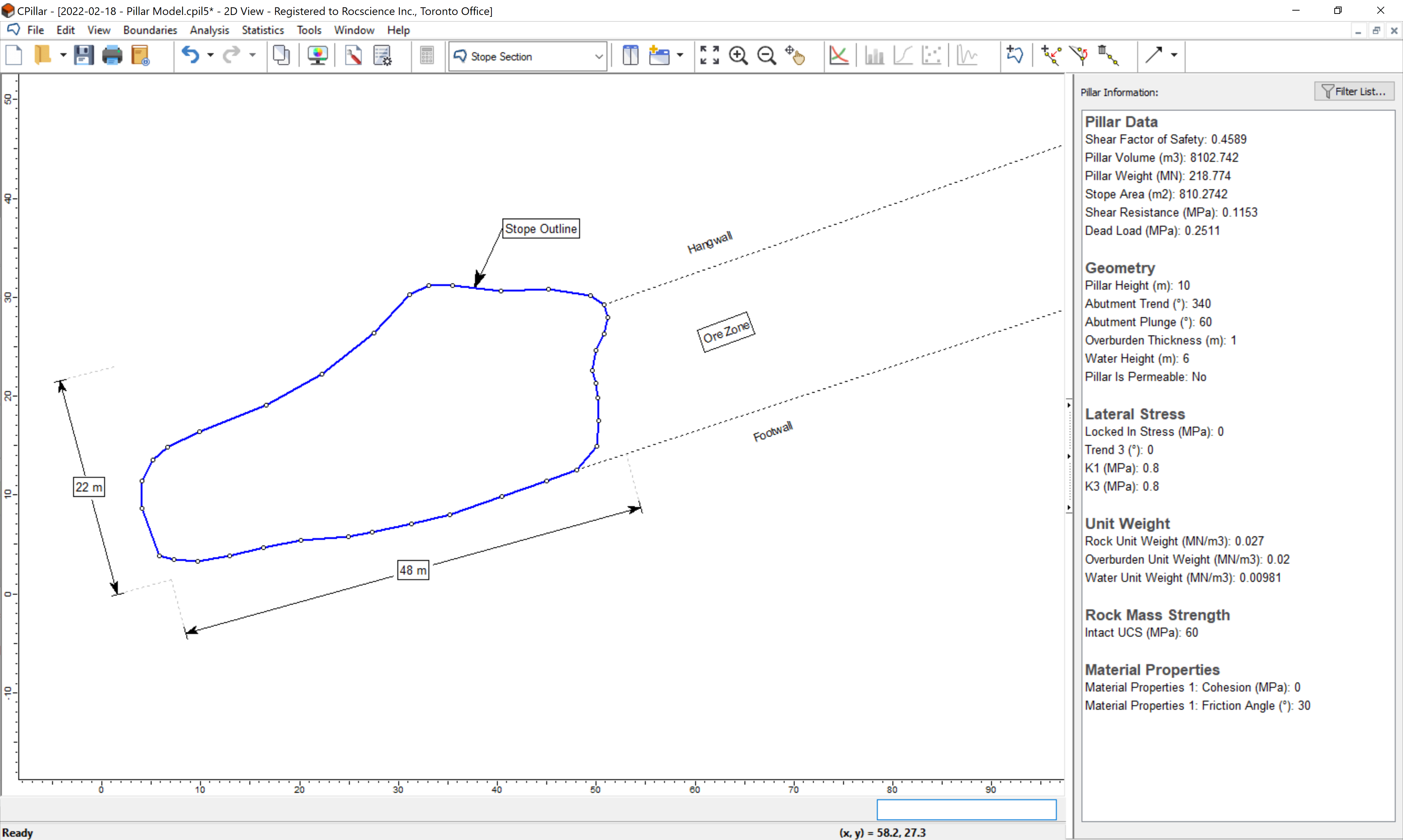
With a dedicated 2D Stope Section View, users are able to easily define the pillar geometry in one of many ways using the Add Stope Section option:
- Graphically, using mouse left-click to draw the polygon
- Entering x, y vertex locations in the prompt line
- Entering or importing from a CSV file a list of x, y vertex locations in a Coordinate Table
The stope section geometry can also be directly imported from a DXF file.
Benefits of Stope Section View
Aside from easy pillar geometry definition, this view also provides users with several useful annotative Tools such as text, shapes, images, and dimensions for labeling and markup purposes.
If users want to overlay a satellite or sketch image as a guide for tracing out the stope section outline, they can easily import, position, and scale the image using the Import Image Wizard option. Once the image has been added to the Stope Section view, users can then use the Add Stope Section option to define the stope section geometry.
Also new to CPillar is the ability to define and assign different shear properties to each abutment. If more than one material property is defined, material properties can be assigned graphically to each abutment in this view by using the Assign Materials option and left-clicking on the segment.
How to use the Stope Section View?
Navigate to the Stope Section view by selecting Stope Section from the toolbar dropdown or View > Select menu. By default, a 10 by 10 square pillar is shown. In order to create a user-defined polygonal stope section, ensure that Pillar Shape is set to Polygonal Pillar in Project Settings (this will limit the Analysis Method to Rigid only).
- To define the pillar geometry, select the Add Stope Section option from the Boundaries or right-click menu (or import from DXF using the Import DXF option from the File > Import menu). Vertices can be moved or deleted either graphically or by editing the Coordinate Table.
- To add an image, select the Image Import Wizard option from the File > Import menu, or the Image option from the Tools menu. Note that several other annotative tools are also available in the Tools menu.
- To assign already defined material properties to abutments, select the Assign Materials option from the Boundaries or right-click menu. Hover your mouse over any segment to see the data tips for the material property assigned.
More from Rocscience