Solving a 3D Modelling Nightmare - Detecting & Fixing Input Geometry
- Dr. Reginald Hammah, Chief Scientific Officer at Rocscience
Without tools to detect and clean up 3D geometry errors, 3D geotechnical modelling can quickly turn into a nightmare. This is why we’ve invested so heavily in creating tools to solve these errors. This article will argue that the full value of 3D modelling to geotechnical engineering will be realized with these tools.
3D geometry error detection and repair tools are essential for creating realistic geotechnical models. This article will help you understand the common challenges you will likely encounter with input geometry in your 3D modelling journey and point out the various resources we have to help you overcome them.
The Attraction of 3D Geotechnical Modelling
Since computing was introduced into geotechnical engineering and geomechanics, it has been increasingly applied in excavation analysis and design. The power and elegance of computer modelling, combined with the need to maximize our limited information, have driven this trend.
Computer modelling helps geotechnical engineers find helpful solutions and avoid catastrophes. It enables us to predict how excavations and layouts will perform in the real world once constructed. Thought experiments with these tools allow us to deepen our understanding of how excavations and structures behave under various loadings and conditions. Computer modelling is particularly valuable for analyzing problems involving nonlinear materials and anisotropy, as expected excavation responses are hard to predict intuitively in such cases. It allows us to maximize the use of limited input data and resources and compare alternative schemes.
We can all appreciate the power and elegance of 3D modelling. Recent 3D technological advances have empowered how we visualize and understand the performance of underground and surface excavations and geological media (rock masses and soils). They allow us to see geotechnical projects in ways we could not achieve previously and give us new insights into excavation responses and interactions. Because of these attributes, our industry has accelerated its application of 3D modelling. However, we hit significant roadblocks on this journey.
What happened? To construct 3D geotechnical models, we imported geometries from geology, survey, mine planning, CAD teams, etc. Everything looked so smooth and easy. With the imported 3D geometries, we thought we could directly proceed to add our geotechnical inputs and compute and visualize our results. Alas, things were more complicated!
We discovered that input geometries have many errors that must be repaired before use. And we found that the repair process was non-trivial, tedious and could consume as much as 90% of our modelling effort!
Bad input geometries can cause many issues in 3D geotechnical modelling. First, they complicate the development of 3D model geometries by creating problems such as difficult-to-resolve intersections, slow model geometry building and bad numerical (finite element and finite difference) meshes. Geometry imperfections can lead to slow model convergence. Even worse, they can cause incorrect results.
We now know that tools to repair input geometries are crucial. To enjoy the best 3D modelling experience, we must have these features in our modelling software and balance three things: retain sufficient geometry detail that allows good results at affordable computational speed (or resources).
If 3D modelling is to become routine in geotechnical engineering, we need easy-to-use tools to fix input geometry issues quickly. We have developed these tools in our 3D software, which will be discussed later in this article.
3D Input Geometry Errors
The 3D geometry we use to build mining and civil engineering geotechnical models originate from different sources. These include the following:
- Geological surfaces or volumes – these geometries, which represent the different soils and rock masses at a site, are developed from the geological modelling of drill hole data, geophysical surveys, etc.
- Excavation designs – these are 3D CAD drawings or objects developed by teams such as mine planning and tunnel design
- As-built excavation geometries and topographies – these volumes and surfaces are produced by survey departments using technologies such as drones, cavity monitoring systems, GIS, and total stations
- Groundwater surfaces – these are typically phreatic surfaces created from hydrogeological modelling
These 3D geometry shapes, no matter how complicated, are built from triangles (faces) with edges and vertices (meeting points of two or more edges). Due to the limitations of the 3D geometry collection devices and triangulation algorithms, the surfaces and volumes they create are sometimes corrupted by geometric errors. The main errors are as follow:
- Near-degenerate triangles
- Holes
- Non-manifold geometries
- Near-folded triangles
- Self-intersecting triangles
- Inconsistent triangle normals (perpendiculars), and
- Tiny gaps between neighbouring volumes
These geometric errors may not be an issue in the original 3D software that generates these geometries. For example, most CAD modelling tools pay little attention to the consistent orientation of triangle normals. However, for 3D geotechnical modelling, this situation can be fatal.
Defects must be fixed before robust geotechnical models can be built.
We will briefly describe these defects next.
Near-Degenerate Triangles
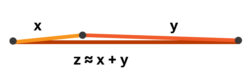
Near-degenerate triangles have near-collinear vertices and near-zero areas. There are two cases of such triangles:
- One interior angle is approximately 180° while the other two are nearly 0°
- Two interior angles are about 90° while the third is almost 0° (one side has near-zero length, and the triangle has near-zero area)
3D geometries can accommodate a few near-degenerate triangles. Several of them, however, can cause severe modelling issues, including non-convergence.
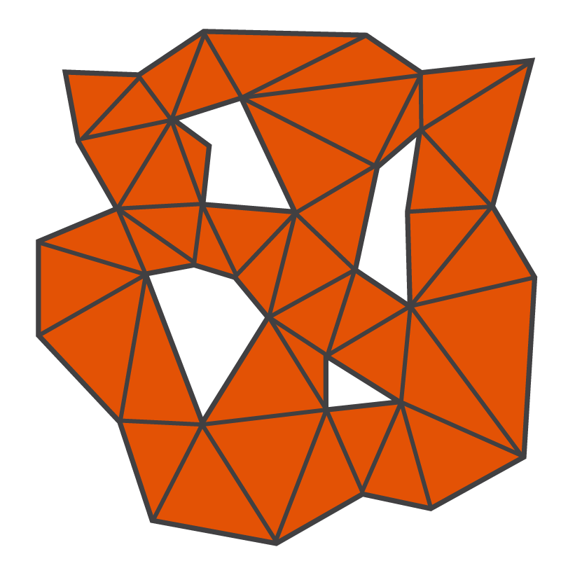
Holes
Holes are missing triangles on triangulated surfaces or volumes, i.e., they are completely surrounded areas of surfaces without triangles. Valid 3D objects must have no holes; all the triangle faces must form one watertight, closed entity.
Surfaces with holes create problems when intersecting with other surfaces or volumes or when they are extruded. Volumes with holes pose similar issues and cannot be assigned material properties in geotechnical models. They can generally not be tolerated in building the geometries of 3D geotechnical models.
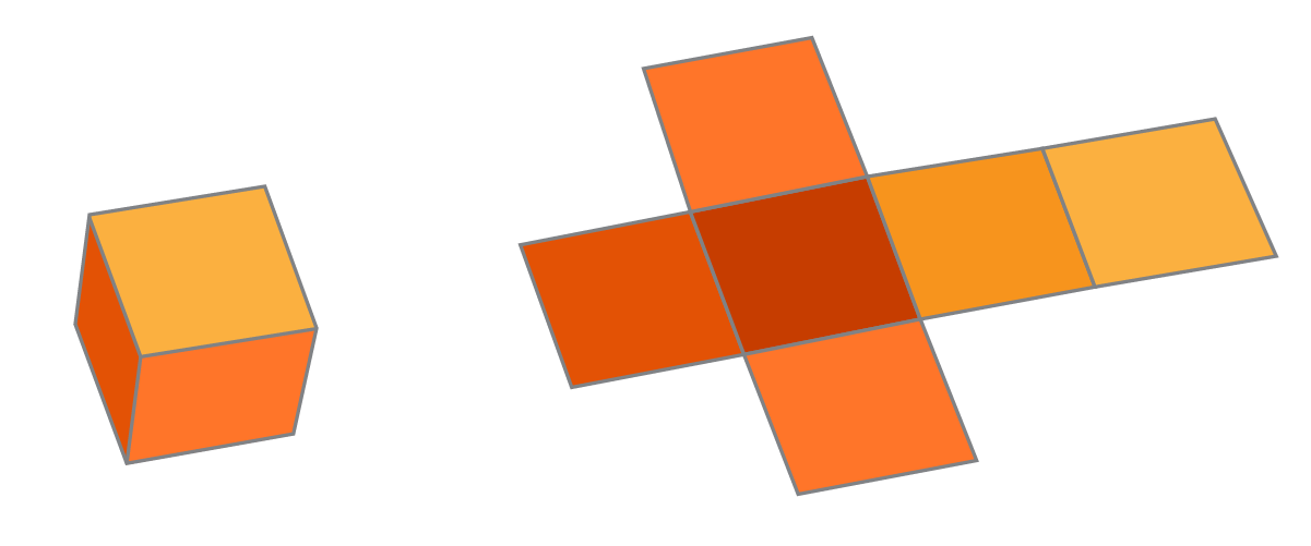
Non-Manifolds
Technically, a non-manifold 3D geometry is a shape that cannot be unfolded into a 2D surface with all its normals pointing in the same direction.
A geometry is non-manifold when:
- An edge is incident to more than two faces, and
- A node is incident to more than one closed volume
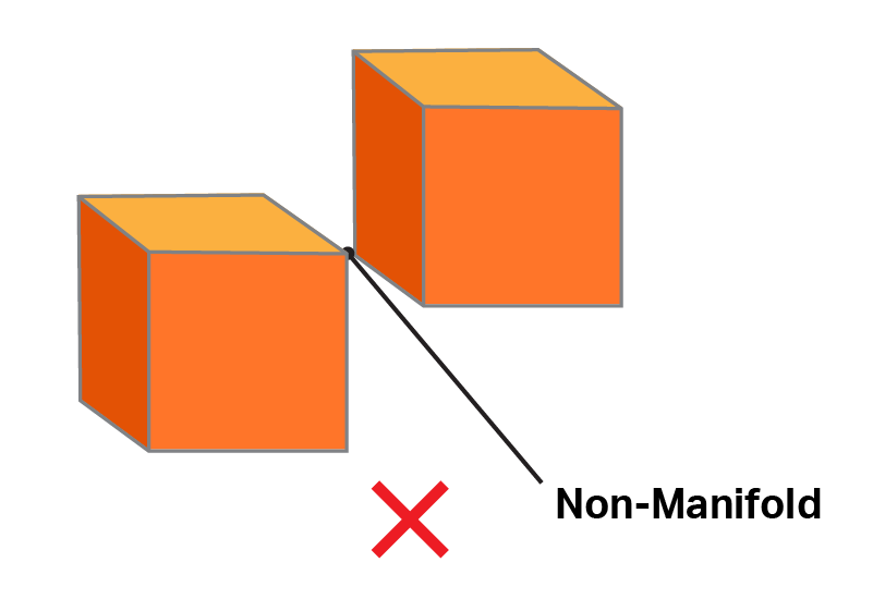
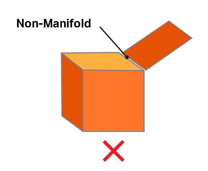
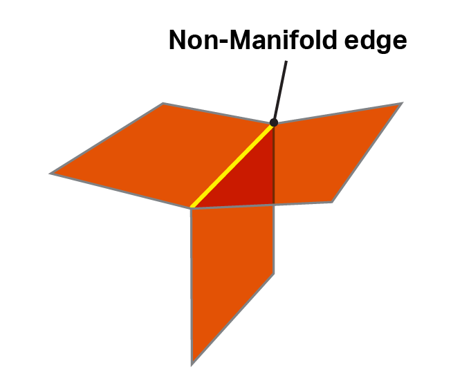
Non-manifold shapes, if unresolved, will cause trouble when you try to use them to build 3D geotechnical models.
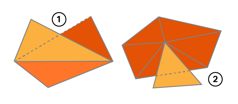
Near-Folded Triangles
Near-folded triangles practically lie over each other. As a part of a surface or volume, they add very little value to the overall geometry description. They only complicate calculations and the generation of numerical model meshes. Consequently, they need to be simplified into better-laid-out triangles.
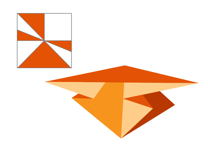
Self-Intersecting Triangles
Self-intersecting triangles pose a problem because they create apparent interiors to geometries, which can confuse 3D model-building algorithms. For example, if a surface area of an object needs to be calculated, it can be determined by simply summing the areas of the individual triangles that form the entity. However, if some triangles self-intersect, the total area is no longer the sum of the components.
Self-intersecting triangles also create conflicts when objects must be intersected or sliced. Self-intersecting configurations can be fixed by re-triangulating such areas into attached faces with no ambiguities.
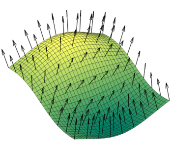
Inconsistent Triangle Normals
In many areas of 3D geometry modelling, it is desirable or even necessary that the normals of all triangles of a surface or volume all point in the “correct” direction. Inconsistent triangle normals can be disastrous for many well-known geometry processing algorithms. They lead to problems such as incorrect volume calculations and the assignment of properties to objects.
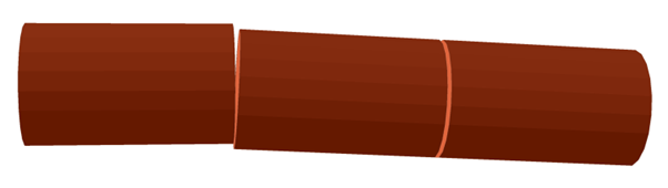
Tiny Gaps Between Neighbouring Volumes
A gap is a space separating the faces of neighbouring objects. Tiny gaps are not necessarily defects of individual objects. However, they can cause considerable problems for 3D geotechnical modelling. They can make numerical meshes unnecessarily large or computations unstable, leading to poor results. Tiny gaps are difficult for users to spot and fix.
Detecting and Fixing Geometry Problems
It would be ideal to have a single tool that detects and fixes all the defects discussed above. However, 3D modelling practice has proved that it is nearly impossible for one fully automated clean-up tool to work consistently for all geometries. Often, troublesome meshes must be fixed with various approaches, and the process can be very time-consuming. (As mentioned earlier, it can consume up to 90% of total modelling time.)
To help geotechnical correct geometry defects, we provide a single set of error detection and repair tools in all our 3D software, namely, Slide3, RS3, EX3, RocFall3 and the newly released RocSlope3.
The process starts when you import geometries. Our software provides information on the number of triangles and previews of simplified triangulations. They also provide functions for automatically detecting and simplifying defects, which will be discussed later.
Once geometries are imported, the programs describe individual geometries with an Entity type. If an object that is supposed to be a volume is assigned a Surface entity type, this is a warning of problems, such as holes, with the triangulation. The Material field is greyed out for such entities.
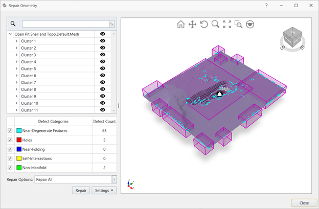
Next, you can select an object and invoke a tool named Repair. When you choose an object and apply this tool, it detects the following five errors: near-degenerate triangles, holes, non-manifold geometries, near-folded triangles, and self-intersecting triangles.
As its name suggests, Repair can also fix problems. However, its default settings, especially for volumes, may have to be modified to get quality outcomes.
Once you have identified any of the five problems with your input geometry with the Repair tool, the software offer several convenient options for repairing the five-listed errors and the other imperfections outlined in this article. The geometry fixing algorithms include Retriangulate, Merge, Form Closed Triangulation, Ungroup Disjoint, and Ungroup Non-Manifold. The names are self-explanatory. Form Closed Triangulation, in addition to closing holes in solids, also makes triangle normals consistent. These tools can be applied in isolation or sequentially to repair problematic geometries.
The last (and arguably the most powerful) tool we will mention in this article is Divide All, a 3D Boolean tool. Although primarily aimed at intersecting 3D objects while creating 3D models (including finding the resulting sub-volumes when different objects are intersected), it can be applied to single geometries. Used in this manner, it can automatically simplify geometries, form correct volumes from intersecting surfaces, and rectify several errors associated with 3D input geometries. The operation can generate several manifold sub-volumes from a problematic object and close gaps between entities within a specified tolerance (when one of its options, Strict Constraints, is activated).
In most cases, applying the geometry options described above will be enough to resolve any issues you encounter with your 3D input geometries. In rare cases, some extremely problematic geometries may need to be fixed in the software that generated your input objects.
Mastering Geometry Clean-up
We’ve created videos and documents to help users master the craft of repairing input geometries. After mastering these skills, you can successfully build various real-world 3D geotechnical models, including ones that would have been intractable without the geometry error detection and repair tools.
Concluding Remarks
The number of commercially available geotechnical 3D modelling tools is rapidly expanding. For example, our very recently introduced RocSlope3, a program for analyzing the stability of blocks and wedges in discontinuous rock masses. These software combine advances in computational geomechanics and 3D geometry modelling to enable academics and everyday geotechnical practitioners to solve challenging problems.
For 3D geotechnical modelling to be used routinely, we must have tools to identify and repair input geometry errors readily. And in an automated manner as much as is practicable.
We believe that every engineer with good computer modelling skills can master geometry error detection and fixing.
Next time you build a 3D geotechnical model, you know what to do!