Izmir Metro Tunnel: How Geological Factors Can Impact Your Tunnel Construction
The population of the world has grown rapidly, and advanced infrastructure like metro tunnels has become a necessity to fulfill increasing transportation needs. Tunnel construction goes through many challenges including ground conditions such as fault zones and fractured rock masses as primary risk factors.
This case study explores the possible effects and hazards of the construction of a shallow metro tunnel built on weak and faulted rocks on the neighboring structures. It highlights the pre and post-excavation effects on the adjacent buildings through field observations, 2D modeling of the tunnel route in RS2, and rock support analysis using RocSupport.
The importance of geological and geotechnical investigation for tunnels
Fully understanding the ground conditions through a detailed investigation is crucial to minimizing the risks of tunneling projects. After a thorough geological investigation, the fault zone and surroundings of the Izmir Metro Tunnel Project were defined as risky areas because of the shallow depths in weak rock and soft soil conditions.
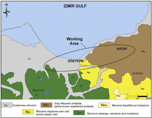
Geological structure of the tunneling project area
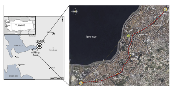
The Izmir Metro Tunnel project is in the south of Izmir province in western Turkey consisting of vulcanites, alluviums, sandstones, claystone, pebblestones (Altindag formation), clayey limestone sequence, and flysch, along the tunnel route. These geological materials are covered with artificial fillings on the surface and have low-to-medium strength.
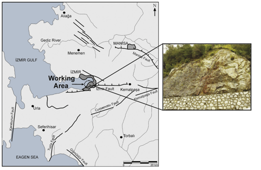
Tectonics and local geology adjacent to the fault zone
Investigating the tectonics of the tunnel region, confirms the presence of active faults. Field studies were conducted in the area and the data revealed that any type of tunneling operation would be affected due to the faults.
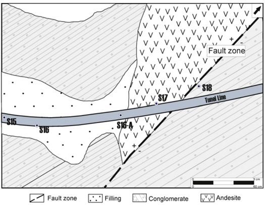
A detailed geological investigation was performed on the fault zone and rock samples that were collected from five boreholes in the impacted area. The most prominent rock units found in this area were Altindag formation, andesite, and alluvium, as shown in Figure 4.
Hydrology: Geological units on the tunnel route has shown unique characteristics of hydrogeological properties. Underground water was set to circulate due to the granular structure of soil units, lithological properties, and characteristics of joint sets of the rock mass.
Engineering rock mass properties near-fault zone
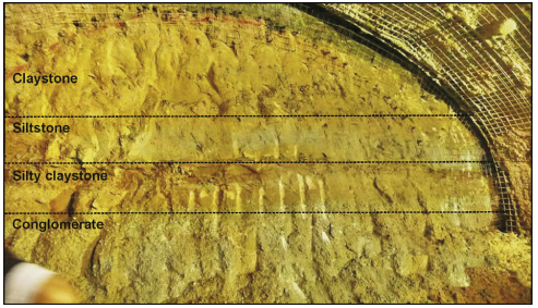
During the fault zone assessment, rock samples were taken from the boreholes near the fault zone and the excavation location for laboratory testing. Rock units found from the drilled boreholes are as follows: fill material, alluvium, and Altindag formation (Miocene-aged sedimentary rocks). It was found that alluvium, claystone, siltstone, and sandstone-conglomerate were overlapping at different depths in the borehole S-15 along the tunnel route.
Fault zone investigation in the tunnel area
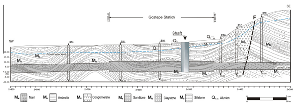
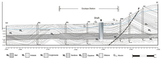
The geological compositions and boreholes around the fault zone along the tunnel route were investigated and a division was found between the site unit and the Altindag formation. The statistical distribution patterns prior to the tunneling and post-tunneling are demonstrated by longitudinal sections. You can see the geological structure of the location, possible fault zone, and the tunnel intersecting the fault zone in Figure 6.
The borehole drilling in the tunnel area indicated that the Goztepe Station which is 80 m away from the fault zone comes within the sequence of Miocene-aged sandstone, claystone, and conglomerate units. However, details of the fault zone, which was totally covered with the dense superstructure, could only be seen on the excavation face during the construction of the tunnel.
As shown in Figure 6 it was anticipated that there is no sign of a fault in the tunnel planning stage, but Figure 7 shows fault traces after the tunnel was formed.
RS2’s 2D modeling of the tunnel fault zone
To detect the potential risks of tunnel construction and the fault zone’s impact on adjacent buildings, RS2’s finite element analysis was used to simulate the problem. Further, the results were compared and tested against the deformations measured in the tunnel area to determine their reliability.
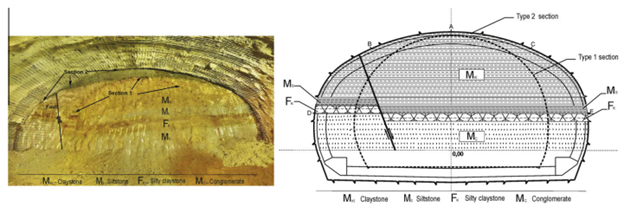
The data required for RS2’s numerical modeling was assembled in two separate groups - properties of rock formation and support parameters. Support parameters that are considered for the numerical modeling of fault-tunnel intersection type 1 and type 2 tunnel cross-sections are summarized in Table 1.
Parameters |
Value |
Height |
Type 1 – 6.45 m |
Type 2 – 7.73 m |
|
Excavation area |
Type 1 – 64m2 |
Type 2 – 113 m2 |
|
Support parameters (NPI 120) |
|
Material behaviour |
Elastic |
Young’s modulus |
210.000 MPa |
Poisson’s ratio |
0.2 |
Thickness |
0.00143 m |
Rock bolt parameters |
|
Length |
4 m |
Distance between rock bolts |
1 m |
Table 1- Tunnel excavation and support parameters
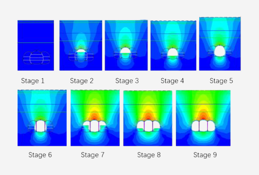
By analyzing the unsupported tunnels, it was found that the horizontal to vertical stress ratio was varying between 6.89 to 10.5 which can cause tensile and shear failures on the walls of the tunnels. Therefore, significant deformations around the tunnel and on surface structures above the tunnel-fault intersection were expected to occur as shown in Figures 9 and 10.
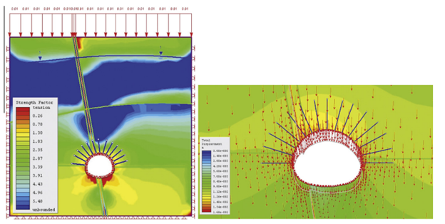
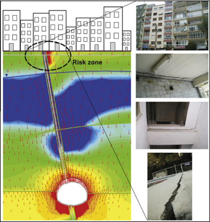
Excavation and support installations in shallow metro tunnels in weak ground need careful planning and consideration of the geological compositions and potential damage along the tunnel route. Subsidence or ground settlement values obtained from both numerical modeling and in situ measurements predict higher settlement values than the allowable value. Further, the buildings situated in the risky zone were investigated and the results are displayed in Figure 10 where deformations and subsidence amounts are within compatible ranges between the numerical simulation results and field observations.
Interaction analysis with RocSupport
RocSupport was used to evaluate rock failures and required supports to retain the stability of the excavation. The approximation method helped determine the extent of the plastic zone around the circular excavation.
The fault zone was analyzed with ground-reaction curves based on the isostatic stress conditions for soft and poor rocks and hydrostatic stress conditions for the rocks bearing groundwater at the distance of 2 + 400 – 2 + 500 km.
Results obtained from the tunnel monitoring system
Deformations on the ground surface in and around the fault zone were identified by constantly reading and monitoring the subsidence rates collected through bolts that were installed in the tunnel path shown in Figure 12.
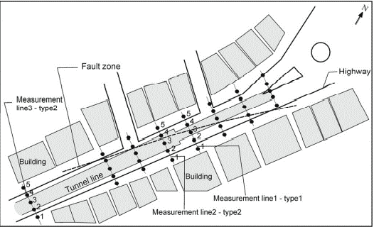
The subsidence values were interpreted and applied to record the effects of tunnel excavation on the surrounding buildings. The maximum subsidence value was determined when the tunnel face was just below the measuring location. Since the tunnel route was directly under the state highway, the values were recorded from 2 different measurement lines (lines 1 and 2 in Figure 12)
Geological survey and numerical modeling with RS2 & RocSupport
The results obtained from RS2’s numerical modeling was compared with the deformations measured in the tunnel and on the ground surface. Based on the evaluation of the results, it was suggested that the excavation and support systems of the original project plan should be reassessed.
Concluding remarks on the importance of evaluating geological conditions prior to tunneling
Geological conditions play a key role in tunneling projects –from understanding rock and soil behavior to identifying stability and surface deformations. By evaluating the geological compositions and using the data in your numerical modeling at the preliminary stage, you can detect risks and potential problems early on. These insights also help you find support requirements for your tunneling project, saving time and additional costs spent on resources.
The complete study is available for you to understand how this project was carried out.