Finite Element Analysis in Verifying Stability of the Melbourne Metro Tunnel
Disclaimer: This case study is a student project and is not the original project design and analysis of the Melbourne Metro Tunnel. It is based on a paper done by students of Monash University in Australia. The case study only represents Rocscience's software support for educational purposes.
Complex geological compositions and existing underground structures can significantly impact your tunnel design and construction. Before planning a tunneling project, it’s essential to analyze the adjacent buildings and underground structures to prevent them from collapsing and select suitable construction measures like a proper alignment for safe excavation.
This case study illustrates the Melbourne Metro Tunnel project which considered simulating excavation conditions and potential risk factors before construction using finite element method programs RS2 and RS3.
Introduction to the development
The Melbourne public transport system is one of the largest infrastructure projects planned in Australia, which involves 9km long twin tunnels across the Melbourne Central Business District (CBD) area and five new metro stations. Due to the increased population and high-rise buildings in the area, any type of tunnel excavation could cause severe settlement and stress redistribution, potentially affecting the twin tunnels, buildings, and historical architecture.
Numerical modeling of the excavation site is considered to detect potential risk factors and analyze the stability of the tunnels well in advance to avoid any type of excessive settlement and failure.
Twin tunnel modeling with Finite Element Method
The finite element method is one of the most effective ways to analyze rock mass behaviour and geotechnical structures built on, in and around them. To evaluate the highly weathered on-site geological units and determine the failure conditions, the Mohr-Coulomb criterion is selected for simulating the behavior of geomaterials.
RS2 is used for modeling the excavation of the State Library Station along with different support systems to assess the influence of existing underground structures and surface loading. RS3’s 3D modeling is used for simulating the twin tunnel and identifying the suitable design alignment with the existing underground Citylink tunnel.
On-site geological parameters
The geological formation in the construction site varies with typical geological compositions, therefore, three sections with typical geological compositions are analyzed and selected to be modelled in RS2. The long section geological profile is shown in Figure 1 and the geological conditions are shown in Figure 1, 2, 3 and Material properties are listed in Table 1.
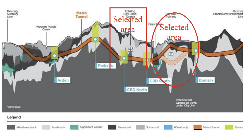
Figure 1. shows two excavations options –
- Excavating twin tunnels above or below the Citylink
- Design twin tunnels in geological units MF1 and MF4
RS3 is used to analyze and better capture the interactions between the twin tunnel and Citylink with the geological information shown in Table 1.
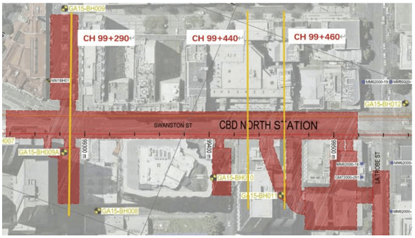
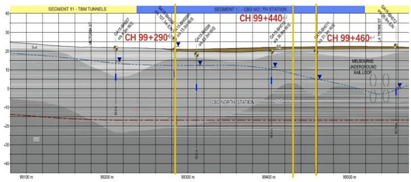
Table 1. (a). Preliminary geotechnical parameters for mined caverns (Golder 2016).
Geological Unit |
Description |
Unit Weight γ kN/m3 |
Effective Cohesion c' kPa |
Friction Angle φ’ |
Secant Modulus E MPa |
Poisson’s Ratio v |
FILL |
fill |
19 |
0 |
30 |
10 |
0.3 |
MF4 |
EW |
22 |
50 |
30 |
80 |
0.3 |
MF3 |
HW |
23 |
150 |
38 |
300 |
0.25 |
MF2 |
MW |
24 |
400 |
45 |
500 |
0.2 |
MF1 |
SW/FR |
26 |
650 |
48 |
2000 |
0.2 |
Settlement analysis with RS2
RS2’s settlement analysis is the most significant part of this study as it shows settlement data on the ground surface and on the top of the tunnel surface. Three different sections at chainages CH99+290, CH99+440, CH99+460 are made with the optimal supporting system to predict and analyze the settlement of the State Library station throughout different construction stages.
Sequence-based Excavation modeling with RS2 and RS3
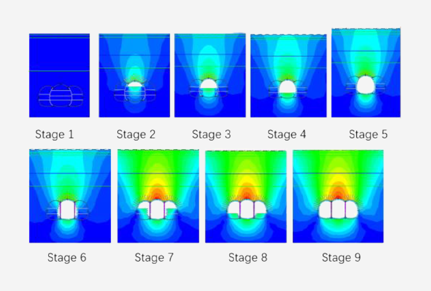
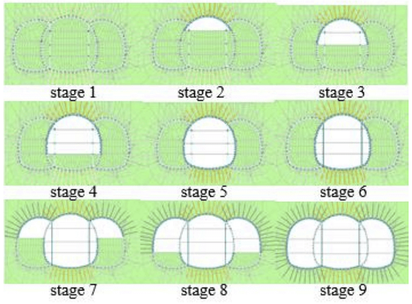
Since excavation sequencing can influence the settlement and stress redistribution around the State Library station, a conventional excavation sequence is modelled in RS2 for step-by-step excavation of the central tunnel and then the side tunnels. Further, an advanced excavation sequence is intended to excavate the side tunnels first, followed by the excavation of the central tunnel.
Since the twin-tunnel alignment design options were limited due to the existence of Citylink, RS3 is used for modeling and analyzing the interactions between the twin-tunnel and Citylink with different excavation alternatives. Further, the twin-tunnel excavation models are analyzed to identify appropriate excavation sequences by investigating the influence on the Citylink.
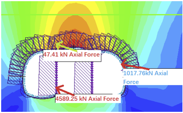
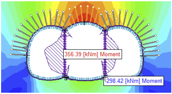
RS2 Results: Figure 6 (a), (b) reveal the diagram of axial force and bending moment on the station and support structures.
Settlement analysis
The settlements on the ground surface and on the State Library Station are analyzed in three sections with chainages CH99+290, CH99+440, CH99+460, and model results are generated to discover how the tunnel excavation will affect the safety of existing buildings on the ground surface and the stability of State Library Station.
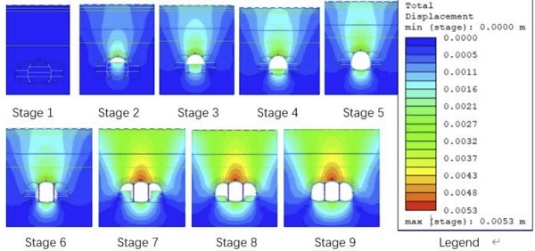
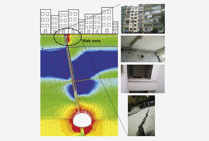
According to figure 7, the largest settlements are located at the critical points: at the top point of the central tunnel station and above the centerline of the central tunnel.
Models for excavation options around Citylink
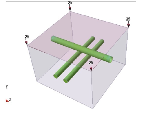
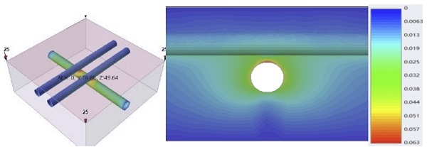
RS3’s 3D modeling is applied for detailed modeling of excavation conditions with the presence of Citylink. The tunnel alignment design options are analyzed, and the results can be seen in Figures 8 (a) and (b), these models are set with simultaneously excavated twin tunnels and 25kN/m2 surface loading.
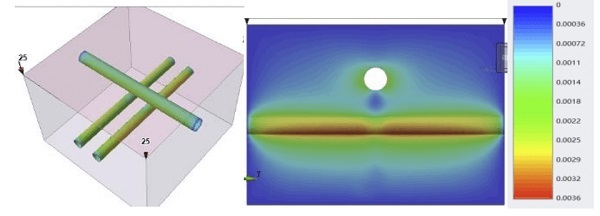
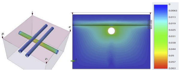
Figure 8 (a) and (b) show that the twin-tunnel excavated above the Citylink indicates a larger settlement of 63mm, resulting in a high risk to the safety of the existing Citylink tunnel. On the other hand, if twin tunnels are excavated below the Citylink, it causes a much smaller maximum settlement of 3.6 mm, proving to be a safer alternative.
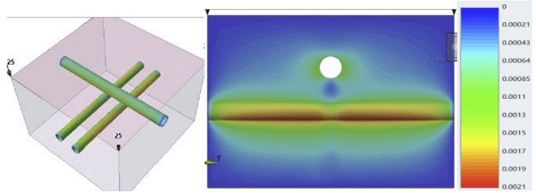
Figure 9 (a) and (b) illustrate twin-tunnel excavation models separately with 25kN/m2 surface loading.
The results obtained from Figures 9 (a) and (b) also discover that less settlement will occur if the twin tunnels are constructed below Citylink. Additionally, a smaller maximum settlement of 2.1 mm of twin tunnels can be obtained by separately excavating twin tunnels. Based on this simulation, it is suggested that the twin-tunnel should be excavated individually and below the Citylink at 38m depth for safety and reduced settlement impacts on both the twin tunnels and the existing Citylink tunnel.
RS2 and RS3’s joint effort for accurate settlement prediction and assessment
This study highlights RS2 and RS3’s finite element analysis of settlement prediction of excavations and assessment of underground structures prior to the construction of the Melbourne Metro Tunnel project. The simulation provides appropriate design recommendations and identifies potential factors that could affect this development.
Read the full paper for a detailed overview of settlement prediction and stability analysis.