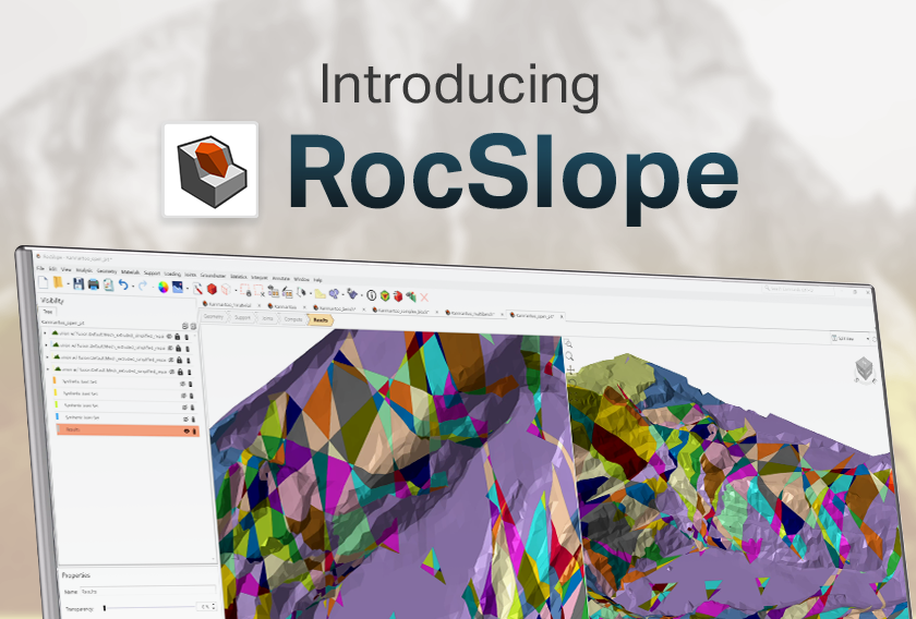
Integrating DIPS & RocSlope3
- Angela Li, Geotechnical Project Manager
Welcome to the new era of DIPS.
This integration is designed to streamline your geotechnical analysis process and provide you with a comprehensive solution for structurally-controlled slope stability assessment and risk management. The DIPS integration with RocSlope3 offers enhanced workflow efficiency to easily import geological structural data directly from DIPS to RocSlope3 to build your model.
Starting from DIPS
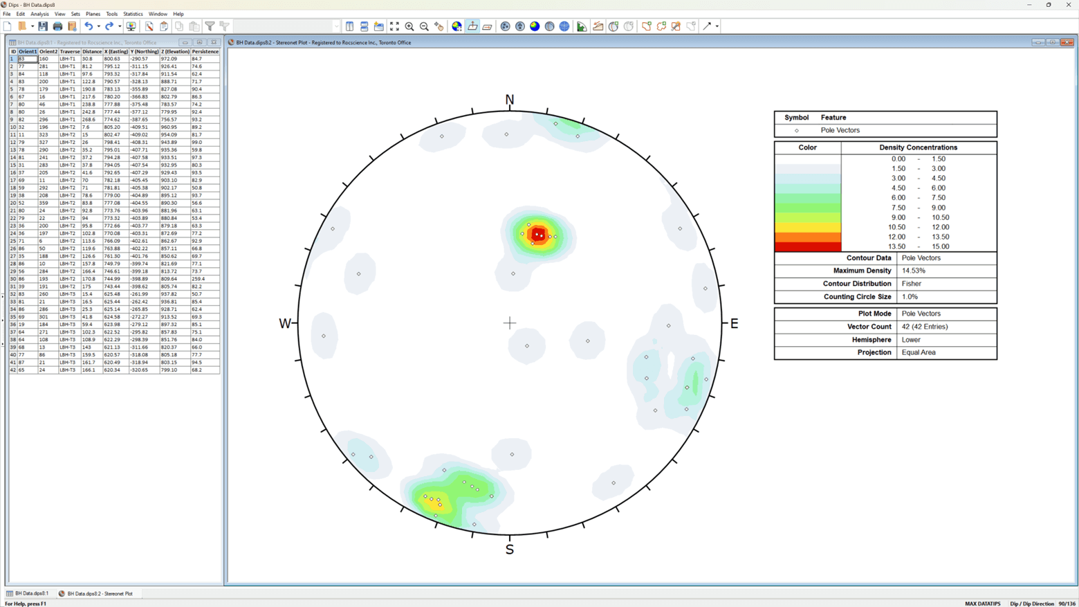
DIPS is an interactive program designed for the graphical and statistical analysis of orientation data. DIPS provides tools and functionalities for data input, analysis, and visualization of geological structures. It allows you to input orientation data of planar features collected from field measurements or other sources. Various analyses can be performed to determine folding, strike frequency, joint spacing, sets and set statistics, which provide insights into the structural characteristics of the rock mass. In addition, as a precursor to advanced analyses methods, DIPS’ Kinematic Analysis serves as an indicator to potential structurally-controlled slope failure.
DIPS is a likely starting point for users with raw, unprocessed orientation data collected from the field either through scanlines, wall mappings, boreholes, or photogrammetry. In the case of data collected along an oriented core or if a declination is applied, orientations are processed by DIPS to obtain the true dip and dip direction.
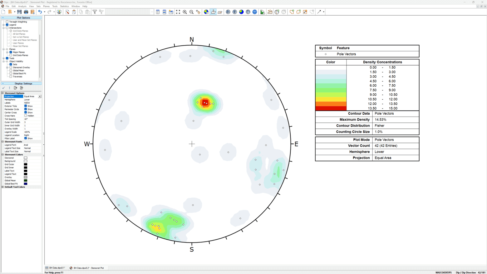
A Kinematic Analysis can then be performed in DIPS to establish if unfavourable planar or intersection vectors exist within your slope dip direction limits.
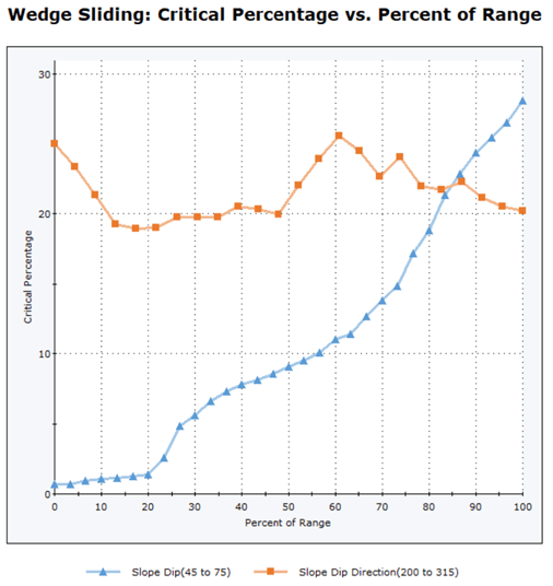
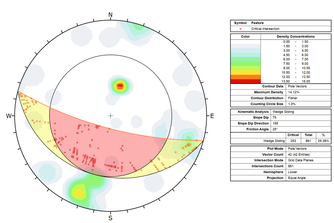
Once sliding is deemed kinematically feasible and the critical joints are identified, it is time to take the analysis further in RocSlope3.
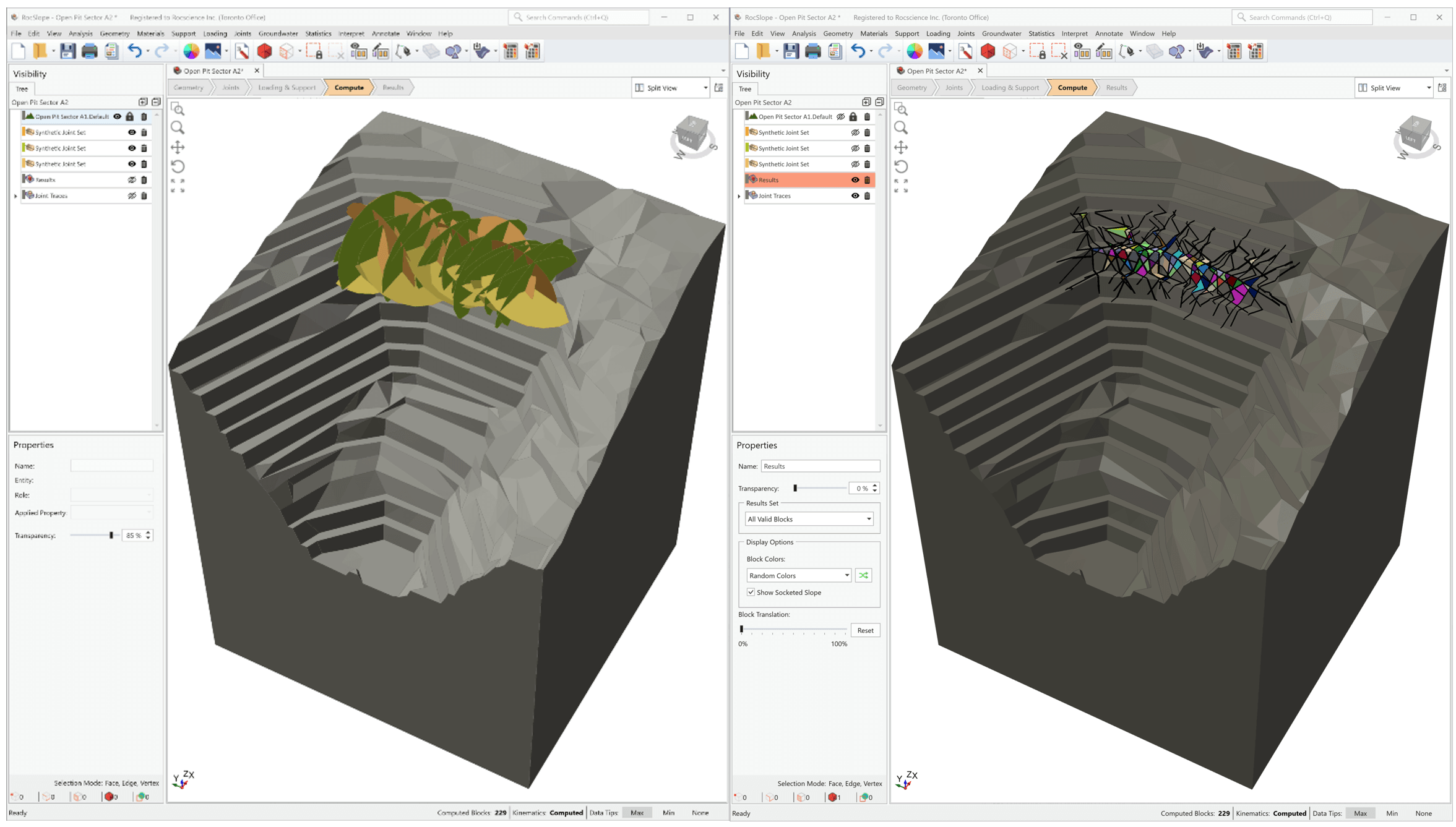
Taking it Further in RocSlope3
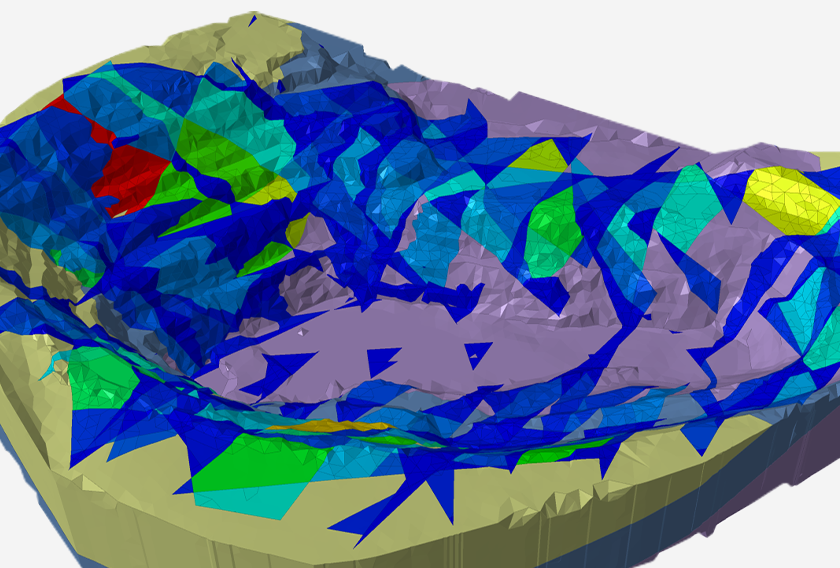
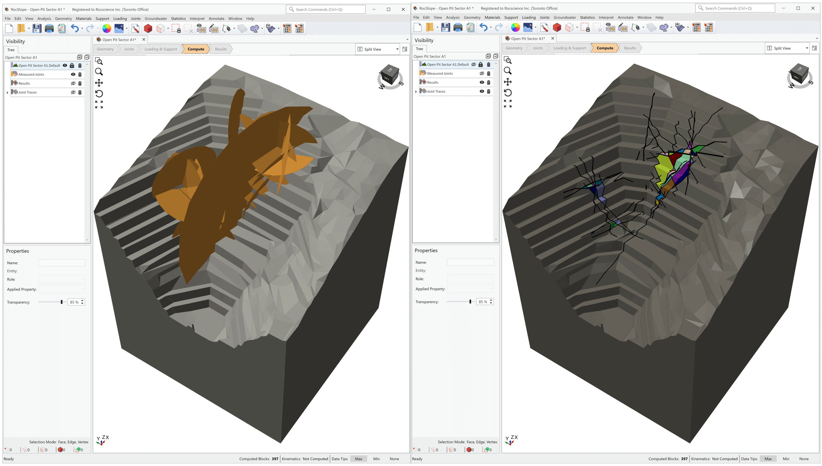
RocSlope3 is a 3D limit equilibrium program used for the analysis of block stability and rock slope risk assessment. With RocSlope3, the user can determine:
- If discontinuities intersect and persist in such a way to create discrete blocks which can daylight and be removed
- Block factors of safety by modeling various forces acting on the blocks, including, seismic loads, external loads, water pressure, supports, shear strength
- Regions on the slope with the lowest factor of safety, largest failure volumes, and highest support demands.
One of the key steps to model creation in RocSlope3 is defining the joints. This is where the DIPS integrations comes in handy to make the user’s workflow more efficient.
Measured Joints
For data collected along a borehole traverse, DIPS can determine the spatial location of the plane using the borehole’s starting point (i.e., Collar Data) and orientation (i.e., Traverse Orientation for a Linear Borehole, or Survey File for a Curved Borehole), and the Distance column in the Grid Data which measures the distance along the borehole where the measurement was taken, starting from the collar. The X, Y, Z columns in DIPS Grid Data can be automatically computed by DIPS with the Compute Locations options. The Persistence column can also be added to the DIPS Grid Data to record joint size information.
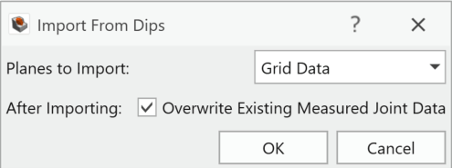
Once the DIPS Grid Data is set up with properly filled X, Y, Z, and Persistence columns, it can be easily imported into RocSlope3 as Measured Joints. As the name suggests, when modeling Measured Joints in RocSlope3, it is assumed that each joint’s orientation, location, and size are measured and exactly known. Grid Data from DIPS once imported to RocSlope3, are used to define the Dip, Dip Direction, X, Y, Z, and Radius values of the Measured Joints. The Import DIPS option is available in the Define Measured Joints dialog. Simply select the DIPS file (.dips8 extension) and set Planes to Import to Grid Data and with a single click on OK, all the Grid Data is imported to the appropriate columns.
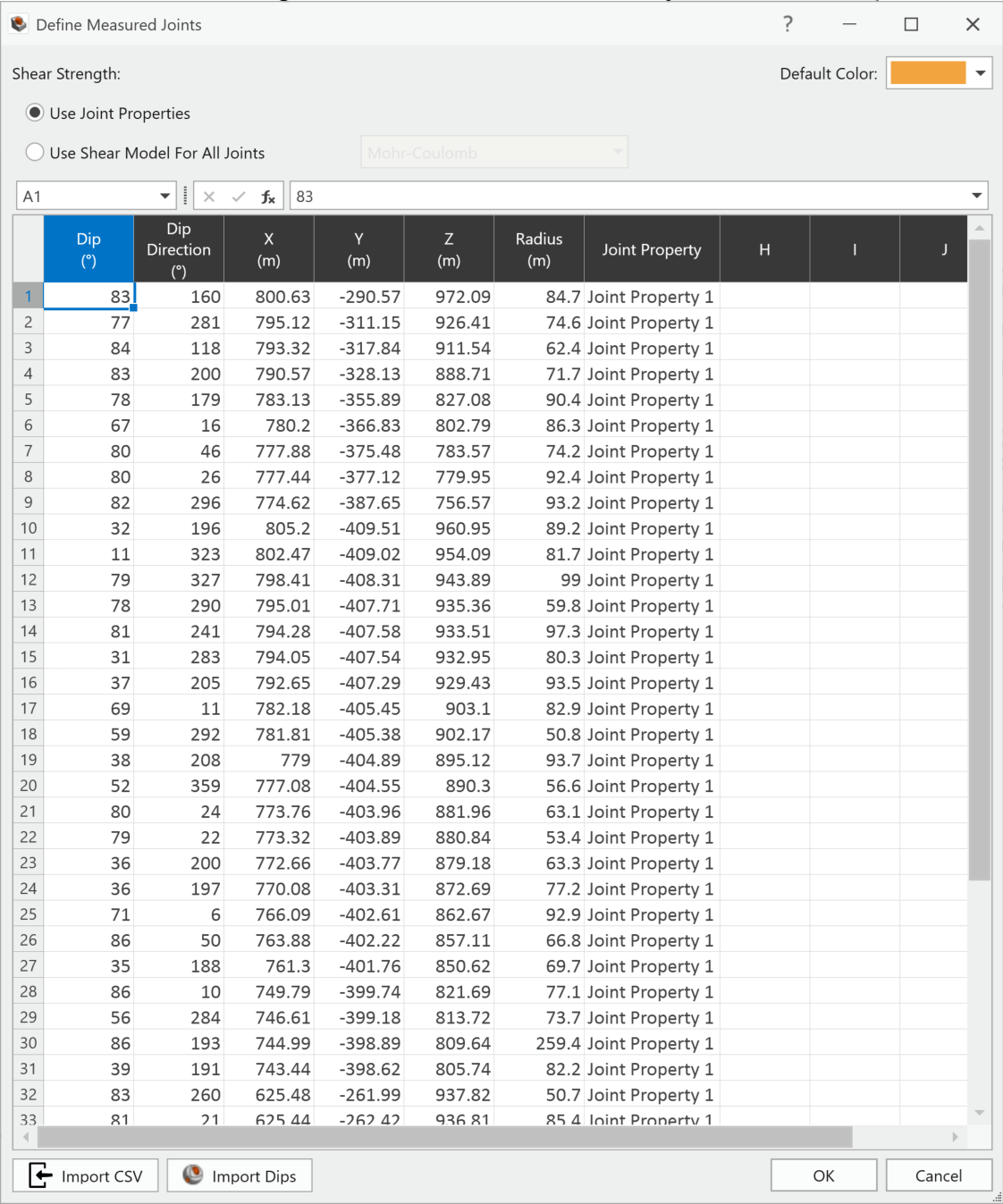
Now, the only thing left to do is assign a joint property to each joint.
Synthetic Joint Sets
In cases where field data is limited or incomplete, exact locations and orientations of measurements may be unavailable or uncertain. In RocSlope3, a Synthetic Joint Set is an artificially generated collection of near-parallel joints and is created based on the distributions of joint orientation, size, and spacing.
For any DIPS file with Sets defined (added via Add Set Window, Add Set Freehand, Add Set Circular, and/or Sets from Cluster Analysis), the set statistics are automatically computed by DIPS.
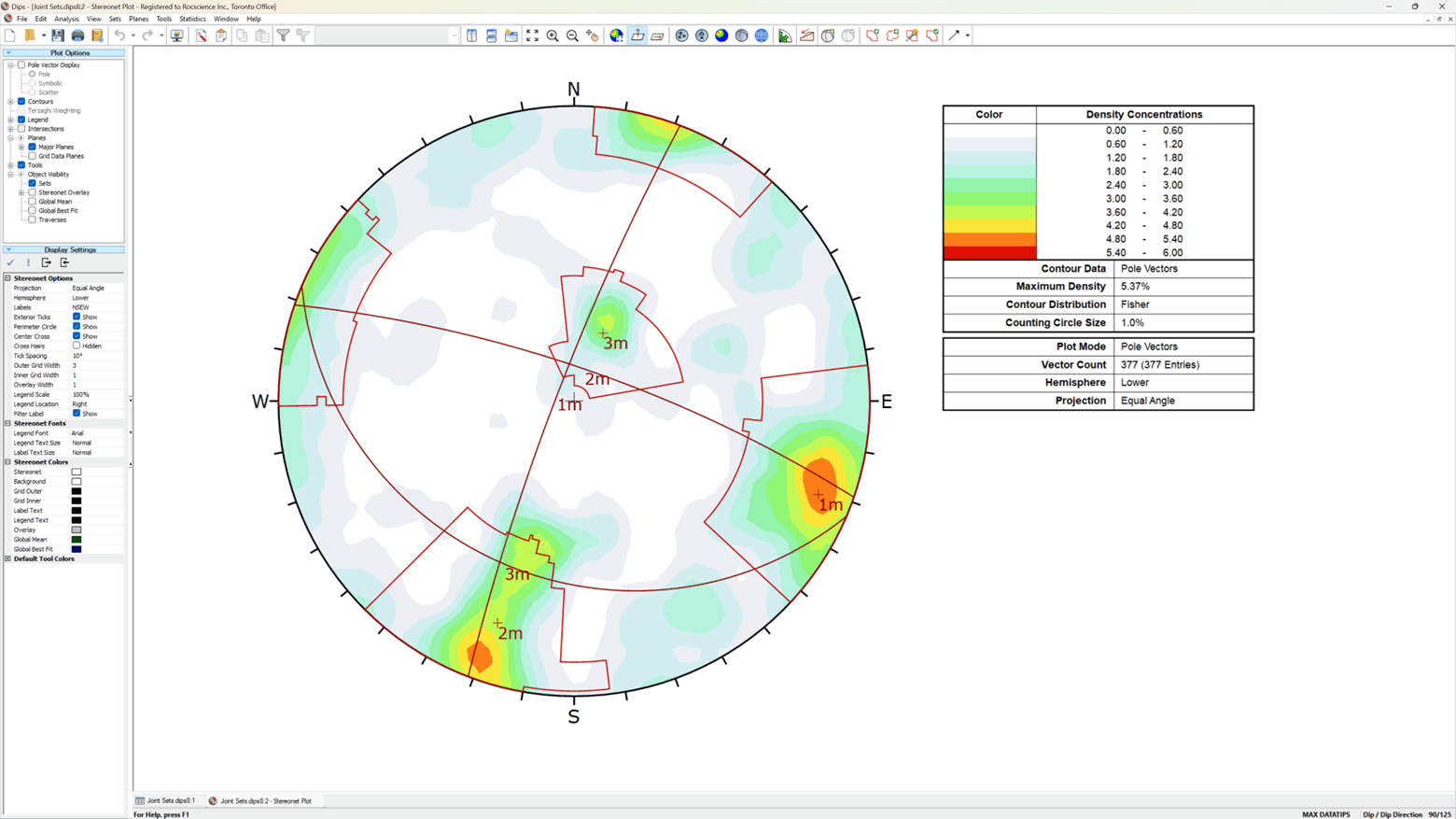
DIPS set statistics can be imported to RocSlope3 to define Synthetic Joints using the Import From DIPS option in the Define Synthetic Joint Properties dialog. Simply select the DIPS file containing at least one set (.dips8 extension) and a preview of all joint sets are listed with Name, Set ID, Dip, Dip Direction, and Fisher K.
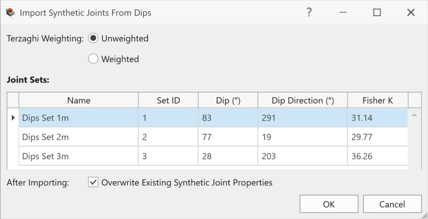
Again, the import is as simple as a click on OK, and all the joint set orientations are imported as separate Synthetic Joint Properties into RocSlope3 using the Fisher distribution with Mean Dip, Mean Dip Direction, and Fisher K values.
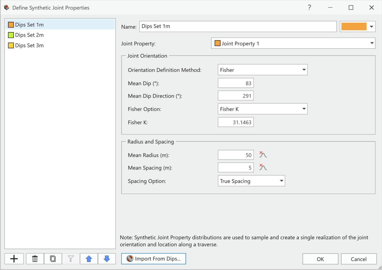
The Radius and Spacing can also be manually set with a statistical distribution. The joints are then sampled across a traversal path according to the statistical parameters specified.
RocSlope3 Seamlessly Connected
RocSlope3 further integrates with our suite of software with three additional integrations:
SWedge – The integration between RocSlope3 and SWedge allows you to import geometry, properties, and joints from SWedge to RocSlope3 to fully define the model.
Slide3 & RS3 – A benefit to using our 3D tools to create your model is that they can be used in other programs. You can import geometry and model inputs like properties, groundwater, Search Limits (Slide3), Joint Surfaces (RS3) from models created in Slide3 and RS3 directly into RocSlope3. You can also take the geometry created in RocSlope3 and take it to Slide3 or RS3 for further analysis.
More from Rocscience