Using RS2 to Examine the Deformation and Support of Highly Stressed Sedimentary Rocks
By Ross Seedsman. Seedsman Geotechnics Pty Ltd, Mittagong, Australia
Fine-grained sedimentary rocks such as mudstones and sandstones are layered and of relatively low strength. In addition to there being a discernible texture within the matrix, layers can be in the form of discontinuities with spacing sometimes measuring less than 10 cm. Although this type of rock can never be considered as an isotropic continuum, it is also not practical to explicitly model all the possible discontinuities as joints. This paper presents an approach to examining the deformation and support of highly stressed sedimentary rock that assumes an anisotropic continuum with an equivalent Independent Shear Modulus (E/G) readily calculated from the spacing of the layer discontinuities and joint stiffness in the order of 1000 MPa/m.
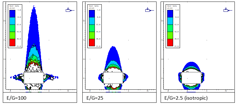
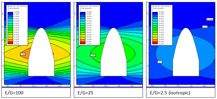
One result of adopting transverse anisotropy is the recognition of significantly different patterns of stress redistribution around rectangular roadways such as those used in coal mining. As an example using Rocscience RS2 is a simple metric for anisotropy that is the ratio of Young’s Modulus to the Independent Shear Modulus (E/G): thinly layered rock has an E/G ratio of 100, moderately layered rock a ratio of about 25, and massive rock (=isotropic) a ratio of 2.5.The models presented in Figure 1 taken from RS2 show contours of the ratio of the major and minor principal stress for a horizontal stress ratio of 1.8.
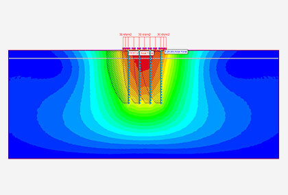
For layered rocks, the Generalised Hoek-Brown criterion is not considered valid as at no scale can the rock mass be considered isotropic. Fortunately, one of the case studies used by Martin, Kaiser, and McCreath (1999) to develop their brittle rock model involved a tunnel in sedimentary rocks. Building on this work, this paper proposes that, for highly overstressed sedimentary rocks, a spalling limit of 7.5 can be used to predict the maximum height of failure. As an example, for a 50 MPa rock (E=12.5 GPa, E/G=100, K=1.8), the predicted failure height above a 5 m by 3 m roadway is 6.25 m. Experiences in some of the deep coal mines in Australia suggest that such a prediction is valid, and it is encouraging that the geometry of fall cavities is similar to those predicted.
It is speculated that addressing stress anisotropy with an E/G ratio and an isotropic strength model is as valid, or possibly preferable, to an approach based on strength anisotropy. Certainly, the former provides a better prediction of stress relief between parallel roadways. Furthermore, most of the input parameters are readily obtained: bedding spacing from core logging, joint shear stiffness from direct shear tests, and crack initiation and Young’s Modulus from standard laboratory tests. There is still a need for a spalling limit value, but this can be obtained by back-analysis of extensometry in highly overstressed rocks.
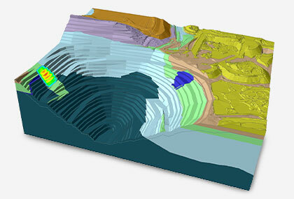
As indicated by Diederichs (2003), current plasticity models are not capable of predicting deformations after brittle failure. Recently, Kaiser (2016) proposed that there is a relationship between tangential strain across a zone of brittle failure and the resulting bulking. If the onset of brittle failure is assumed to result in a new excavation profile, then the transverse isotropy model predicts in the order of 100 mm of lateral movement compared to only 15 mm for the isotropic assumption (see Figure 2).
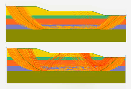
Whereas Kaiser (2016) used a Voroni joint network for the fracturing of igneous or metamorphic rocks, a parallel joint model may better represent sedimentary rocks. A simple RS2 model has been utilised where 100 mm of displacement is applied to both sides a 5m wide and 5 m high volume (Figure 3). The joint network includes bedding spaced at 150 mm and joint sets spaced at 500 mm. Based on underground observations, the fracturing that results from brittle failure has been allocated a dip angle of 20°. Steeper dips have also been used to simulate conditions where the rock mass may be more structurally disturbed – say in proximity to a strike-slip fault.
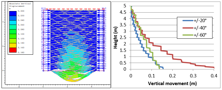
Typical bulking factors in coal mine roofs as revealed by sonic probe extensometry are in the order of 1-3 %. The bulking factors predicted in the RS2 - 20° model are 3% near the base of the model and 1 % near the top. For the 40° model. the bulking factors are greater: 8% near the roof line and about 2% near the top. For even steeper joints the bulking factors are more similar to the 20° case. Since the model is effectively elastic, the bulking factors that would be associated with a 15 mm closure (isotropic case) would be about 7 times lower.
The close match between extensometry and the RS2 joint network models raises a few questions:
- Are there any measurements to confirm the prediction of horizontal closure?
- How do the displacements change with irregular joint spacings?
- How realistic is the prediction of large bulking factors for the 40° dips? These factors are getting too close to the ultimate strain capacity of steel.
References
Ross Seedsman. Interpreting roof extensometry in coal mine roofs, DOI: https://www.tandfonline.com/doi/full/10.1080/25726668.2019.1583458