The Future Modelling of Hard Rock Slopes is Near
The use of limit equilibrium and numerical methods for geotechnical problems, including slope stability, has experienced rapid growth in recent years. This is due to the availability of commercial software and inexpensive computing power. However, are we maximizing the value of such modelling in the assessment of failures and risks in hard rock slope stability? This article explores the question.
Failures in hard rock slopes occur through a variety of mechanisms. These include sliding and opening along individual or combinations of discontinuities. Wedge, planar and block sliding, block toppling, flexural toppling, and buckling are simple modes of hard rock slope failure. (The fact that the mechanisms are termed 'simple' does not mean they are easy to analyze.) Sometimes the mechanisms combine different modes or include failure through intact rock.
The type of failure mechanism that occurs in a part of a slope highly depends on structural discontinuities' orientations within the rock mass and their strengths. The modes vary based on the three-dimensional spatial arrangement (orientation, spacing, and persistence) of discontinuities and the slope angles and dip direction of the slope faces. At large slope scales, failure mechanisms may also involve failure through intact rock material.
Assessing rock slope instability involves understanding the complex three-dimensional interactions between the above-identified factors. Stability analyses for excavations such as open pits are made even more difficult by the presence of different geotechnical domains in different slope parts.
It is possible to recognize the simple mechanisms such as planar failure, wedges, and toppling from kinematic analysis and assess their stability using limit equilibrium methods. However, such evaluations are currently done separately for each type of failure mode. As well, most of the analyses ignore spacing and discontinuity size and consider worst-case block sizes.
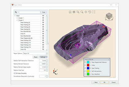
Efforts are underway to develop a software tool that combines kinematic analysis with limit equilibrium methods for the various simple slope failure mechanisms. The new tool aims to perform the analysis in 3D and account for different slope design sectors and rock mass domains. It will use structural mapping data from field measurements, including outputs from external software such as Shapemetrix, PointStudio, and Sirovision.
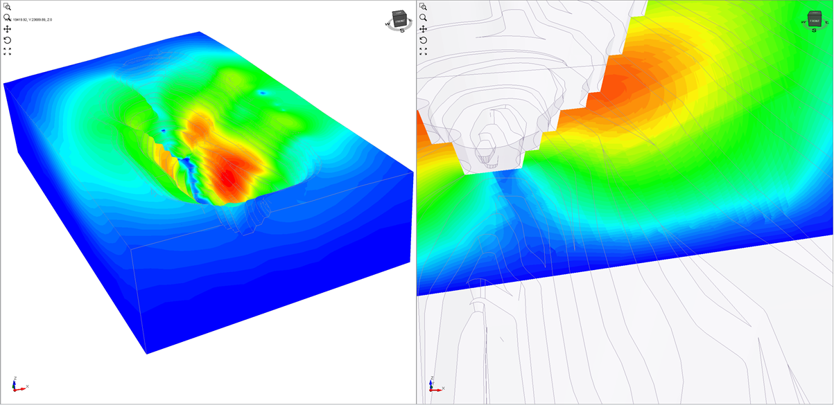
The new 3D limit-equilibrium software will have the capability to filter results by failure type, size or volume of material involved, and failure direction. It will be able to create a risk or hazard map by contouring the factor of safety values.
The new tool will enjoy all the advantages of limit equilibrium analysis, including the computational speed that comes with the simplicity of formulation. The fast computation makes it possible to perform probabilistic analysis with limit equilibrium methods.
Despite their advantages, limit equilibrium methods have some significant limitations. Slope failure mechanisms such as flexural toppling and buckling, which are "statically indeterminate problems" with stress states, are not readily analyzed with only equilibrium equations. Accurate analysis of such modes requires knowledge of stress and strain compatibility, deformation characteristics, and boundary conditions. This is the forte of numerical analysis methods.
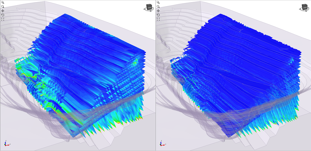
Numerical methods such as the finite element method (FEM), discrete element, and distinct element method can model both intact rock and discontinuities. As a result, they can capture all the simple mechanisms, combinations, and shearing through intact material.
Numerical methods can also simulate progressive failure mechanisms (for example, one that starts from a slope toe and progresses upwards), which are common in the real world. They are particularly beneficial in situations in which stress has a dominant influence on stability. Engineers can use them to gain insights into slope failure mechanisms that limit equilibrium methods cannot match.
Another significant advantage of numerical methods is their ability to automatically determine discontinuity-driven failure mechanisms, including combinations of the simple mechanisms, without prior assumptions on the mechanisms' mode, location, or shape.
Groundwater pore pressures can significantly influence the stability of slopes. Numerical methods readily perform seepage analysis to establish pore pressure regimes and include them in slope stability and deformation analysis.
Slope radar monitoring measurements can be superimposed on the results of both 3D limit equilibrium software (such as Slide3) and numerical software (such as RS3). However, engineers can more readily calibrate numerical models with the monitoring information because these models compute deformations and displacements.
In the past, except in relatively few situations, slope engineers saw numerical methods as unnecessary for rock slope stability analysis. These views stemmed primarily from the computational demands of numerical methods, especially compared power. However, as powerful CPUs with 32 or more cores are becoming affordable to even small firms, the landscape of slope modelling will change rapidly.
We are convinced that routine application of comprehensive limit equilibrium and numerical software to hard rock slope stability, including comparative analysis of the two, has nearly arrived. These robust alternatives can soon provide engineers with vital information on the design and analysis of hard rock slopes. The possibilities are limitless.