ShapeMetriX & RocTunnel3: Streamlining Underground Rock Engineering from Data Capture to Hazard Assessment
- Dr Grace Huang, Geotechnical Product Manager
- Dr Markus Pötsch, Customer Support and Sales at 3GSM
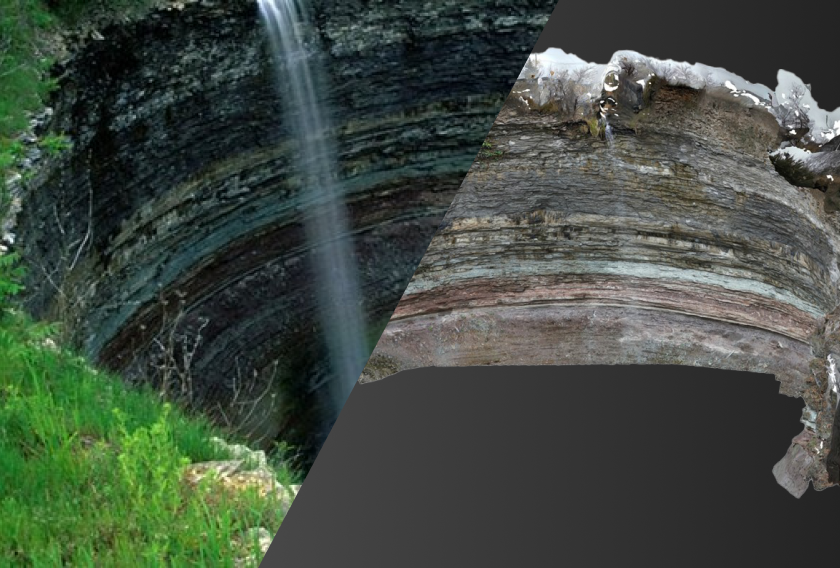
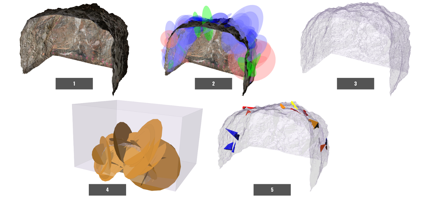
ShapeMetriX and RocTunnel3 provide capabilities to construct and model the 3D as-built excavation geometry and geologic structures positioned relative to the excavation. By integrating the application of these two tools, you can effectively:
- Generate the as-built excavation geometry, including structures, from photogrammetry or LiDAR
- Map geologic structures in 3D by location and size
- Use the as-built geometry and measured structures to find where blocks can form around the excavation and identify the locations and scales of instability
- Assess hazard by realistically accounting for staged excavation and support.
The value of modelling the as-built environment and realistic construction sequence cannot be understated. To name a few, this process allows you to:
- Verify design assumptions against real-world data
- Provide additional basis for rock mass characterization that could improve drill and blast work and inform construction
- Identify potentially unsafe areas and apply remedial measures during construction
- Forecast hazards using a combination of field data and 3D modelling
Expert Tips for Underground Data Acquisition
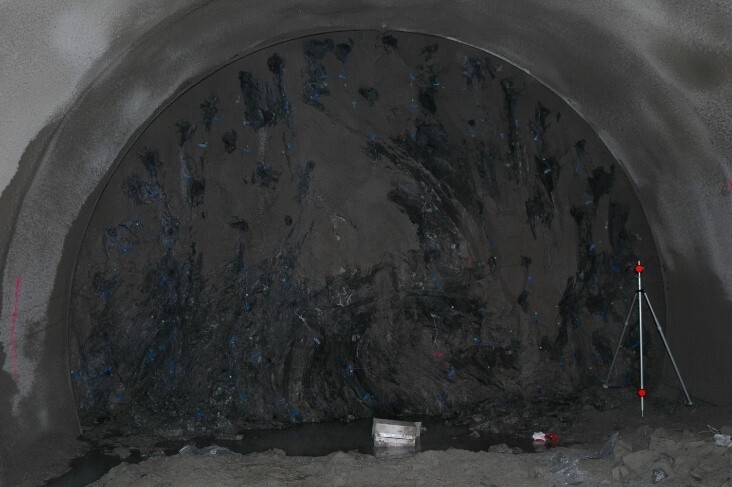
Underground data acquisition has its own set of challenges, including the lack of lighting, potential disruption to device signals, and confined spaces. The following are specific recommendations for underground photogrammetry to help achieve the best model construction results in ShapeMetriX.
Camera and Setup
In underground applications, photos are often taken by still cameras. While cell phone cameras are readily available today, DSLR cameras provide the best image quality, especially under conditions of lower lighting. To avoid blur, a supporting tripod and remote trigger are recommended.
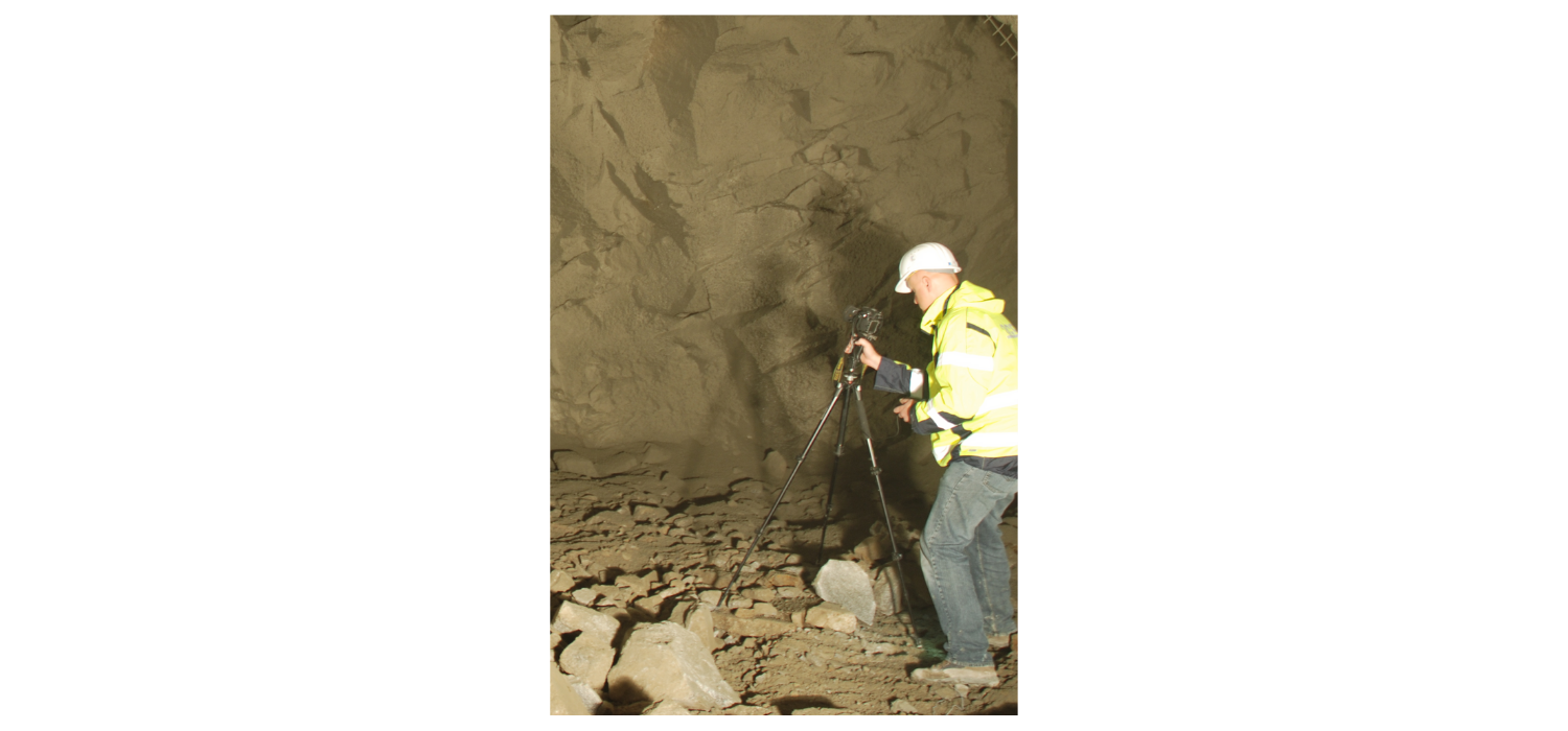
Photos should be taken from a distance and at an angle which provide sufficient detail given the lens and device specifications. 3D measurements are only possible if photos are taken from several different positions and angles, while maintaining an overlap of approximately 80% between adjacent photos. A 3D model can be generated from a handful of photos and onward up to several thousand photos or more.
Lighting
Several sources of flood lighting are recommended to provide a constant source of illumination on all relevant excavation faces. Flood lighting is recommended over flashlights, as it avoids pitfalls such as:
- Varying shadows
- Dust close to the (flashlight) lens that can appear like fog
- Inadequate illumination required for the entire scene
Portable LED arrays are convenient for achieving good illumination while having sufficient battery life for the duration of the photogrammetry campaign. Several light sources are used to minimize shadows on the rock surface.
Georeferencing
Several georeferencing options are generally available for 3D model generation, though mainly two are applied in underground environments:
- Ground control points
- Scale bars (or range poles)
Ground control points (GCPs) are points typically surveyed by a total station and they need to be visible in the photogrammetry images. GCPs can be spray-painted or pre-installed as surveying targets that can also be used for displacement monitoring.
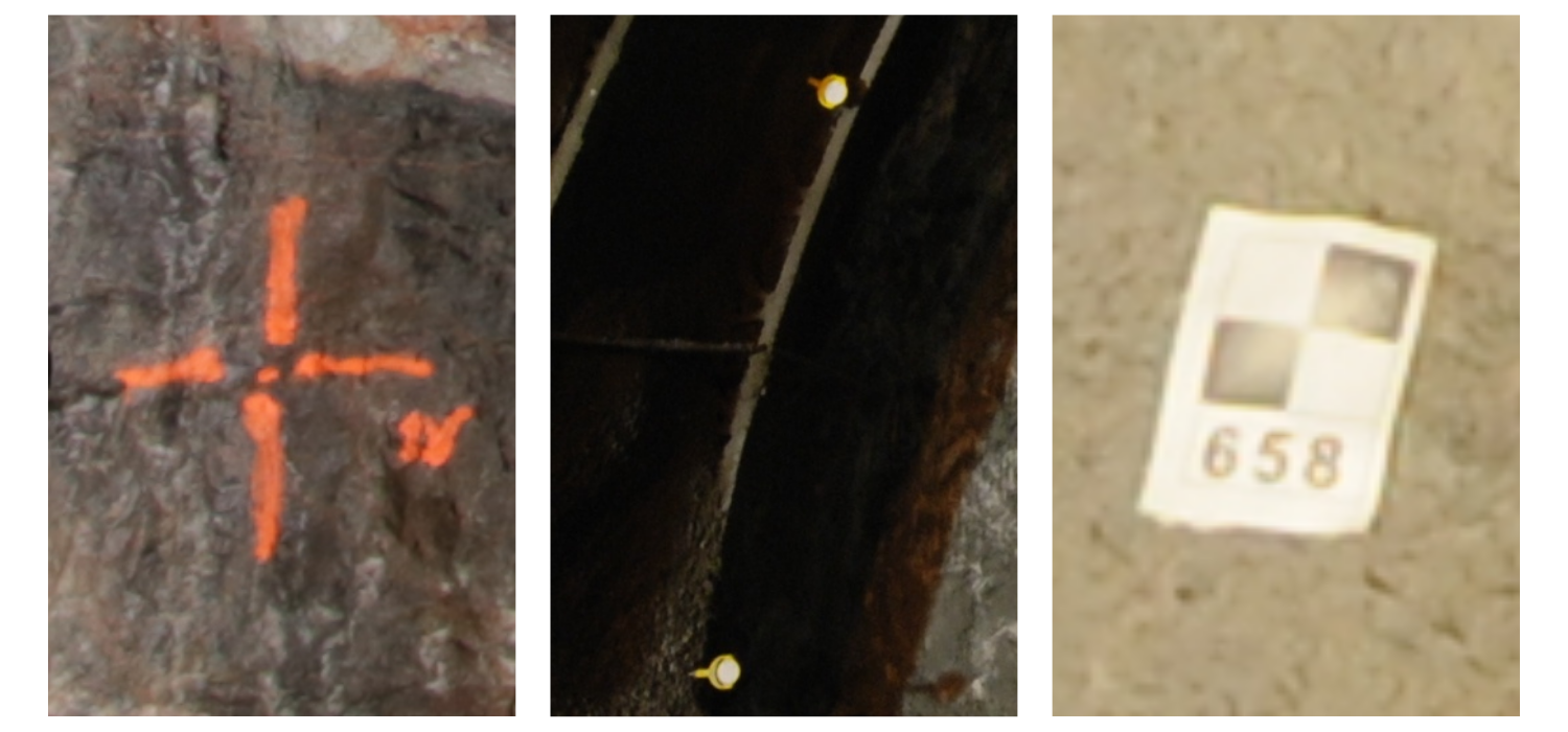
GCPs should ideally be distributed over the entire area of photogrammetry, but that is hardly achievable in practice. A practical setup would typically include approximately 3 GCPs on different sides of an excavation.
The use of a scale bar or range pole instead of GCPs has the advantage of being independent of surveyors and total stations. A range pole provides scale and vertical reference, and declination correction can be provided by an external compass reading or be derived from a known axis of a drift.
LiDAR as a Data Acquisition Alternative
LiDAR with photo texture is also a viable form of underground data acquisition, with ShapeMetriX accepting .e57 point cloud file formats for model generation. Terrestrial LiDAR, as opposed to aerial LiDAR, is predominantly used in underground excavations, where the LiDAR unit is installed at a stationary location much like a DSLR camera is mounted on a tripod for photogrammetry. Terrestrial LiDAR may be advantageous in confined spaces as it bypasses potential challenges in aerial navigation.
3D Model Generation and Block Stability Analysis
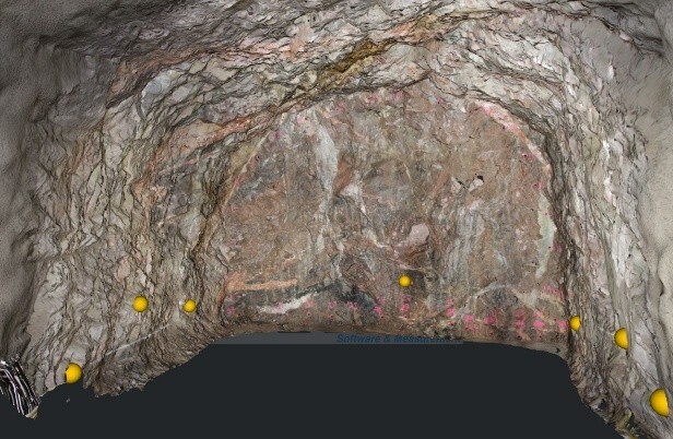
3D Model Generation in ShapeMetriX
The 3D model generation process in ShapeMetriX is widely automatic. After the photogrammetry campaign, photos are loaded into MultiPhoto, the 3D model generation module within ShapeMetriX. Overlapping photos are automatically matched and aligned to generate a textured 3D surface. If desired, the user can adjust the model resolution.
When GCPs are used for georeferencing, 3D coordinates are imported and assigned to the image measurements. A smart user interface supports the user in the assignment process.
If a scale bar or a range pole is used, then the markers on the tool are defined by the user and a known distance is assigned. It is also possible to define a declination correction and a known coordinate in 3D space.
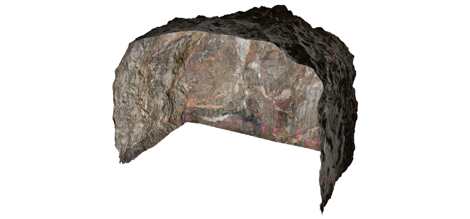
At the end of the 3D model generation process stands an accurate 3D model of the underground excavation in real world scale.
3D Geologic Mapping in ShapeMetriX
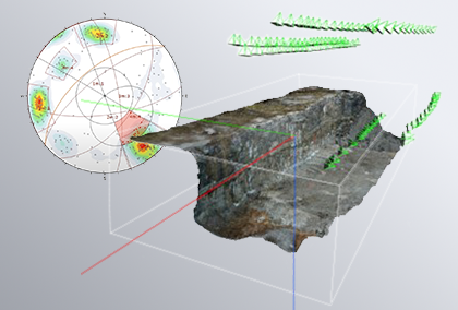
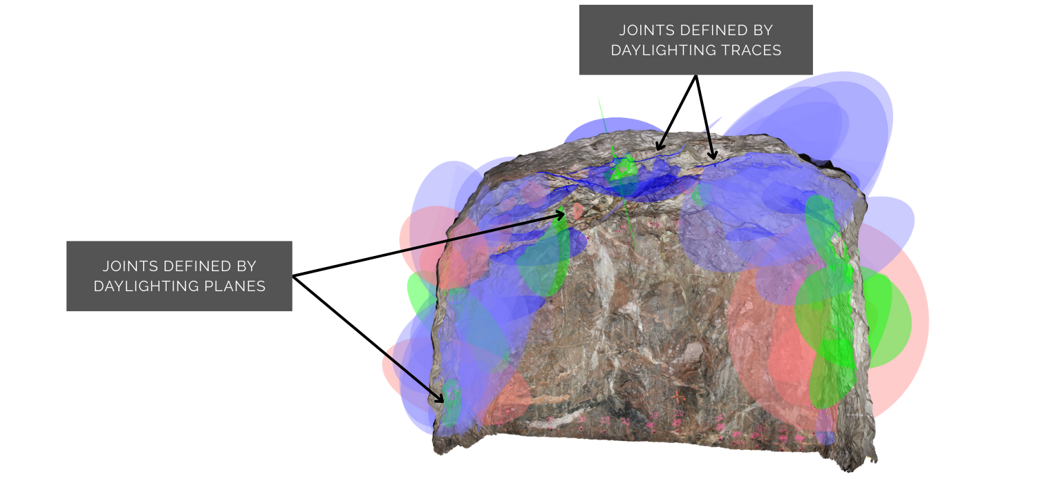
3D structural-geologic data are mapped and assessed in the Analyst module of ShapeMetriX after generating the 3D model. Daylighting joints can be defined from traces as open polylines and from planes as closed polylines. These annotations provide the joint orientation (dip and dip direction), location in space, and apparent size. Mapping is performed either interactively or in a guided fashion with the use of semi-automatic tools. Joints may be extrapolated or projected in size as planar or undulating discontinuities (i.e., with roughness).
3D Block Stability Assessment in RocTunnel3
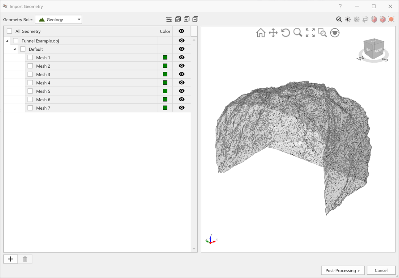
The 3D generated model and mapped joints can be easily imported into RocTunnel3 for underground block stability assessment. RocTunnel3 accepts excavation geometries in common geometry formats, including .obj and .dxf, which are compatible file formats provided by ShapeMetriX. Mapped ShapeMetriX joints can be saved in a .3gdps file which could be directly imported into RocTunnel3. Note that a .3gdps file is also compatible with DIPS, which means further joint set and kinematic assessments could be performed on the same mapped joints.
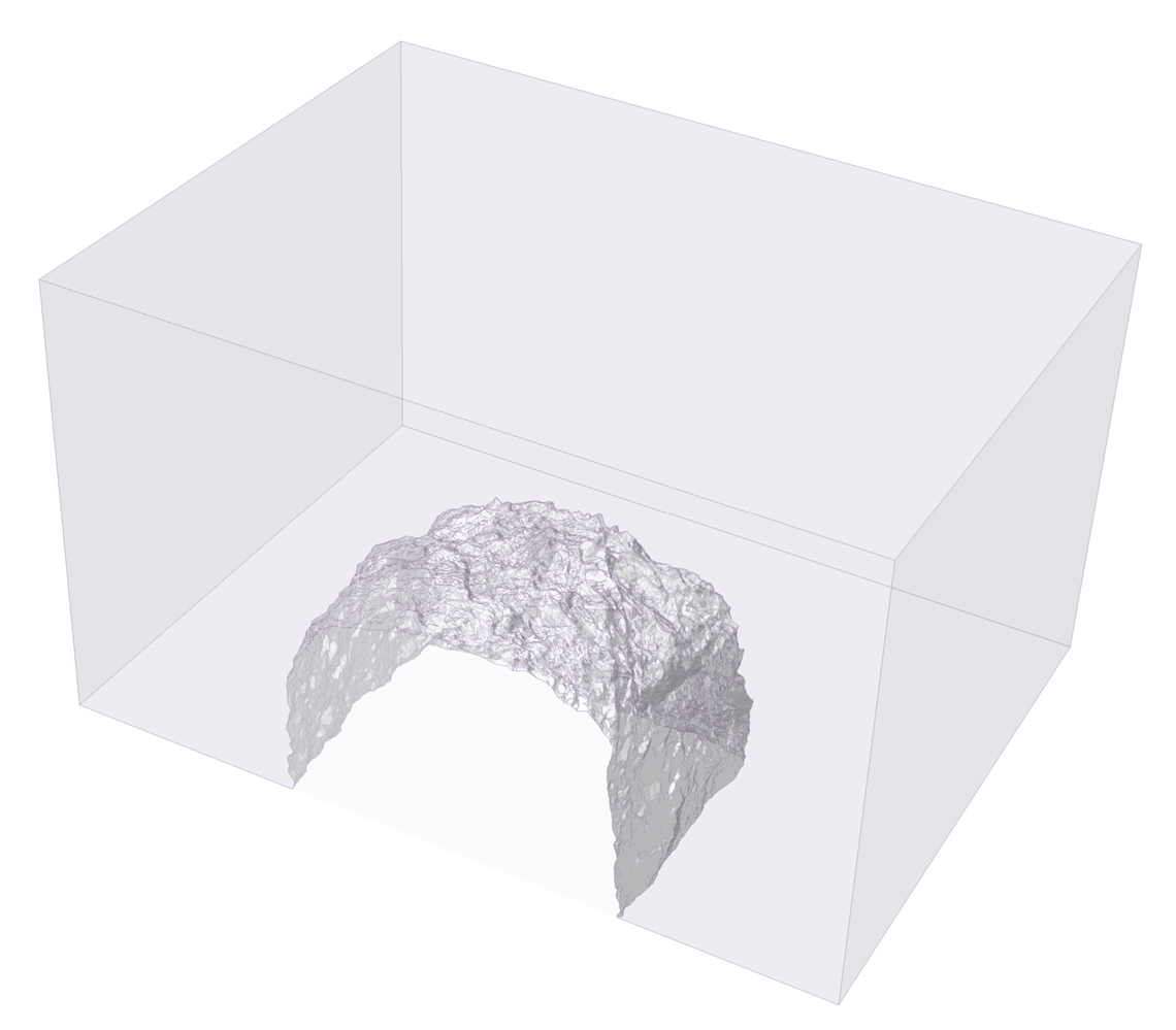
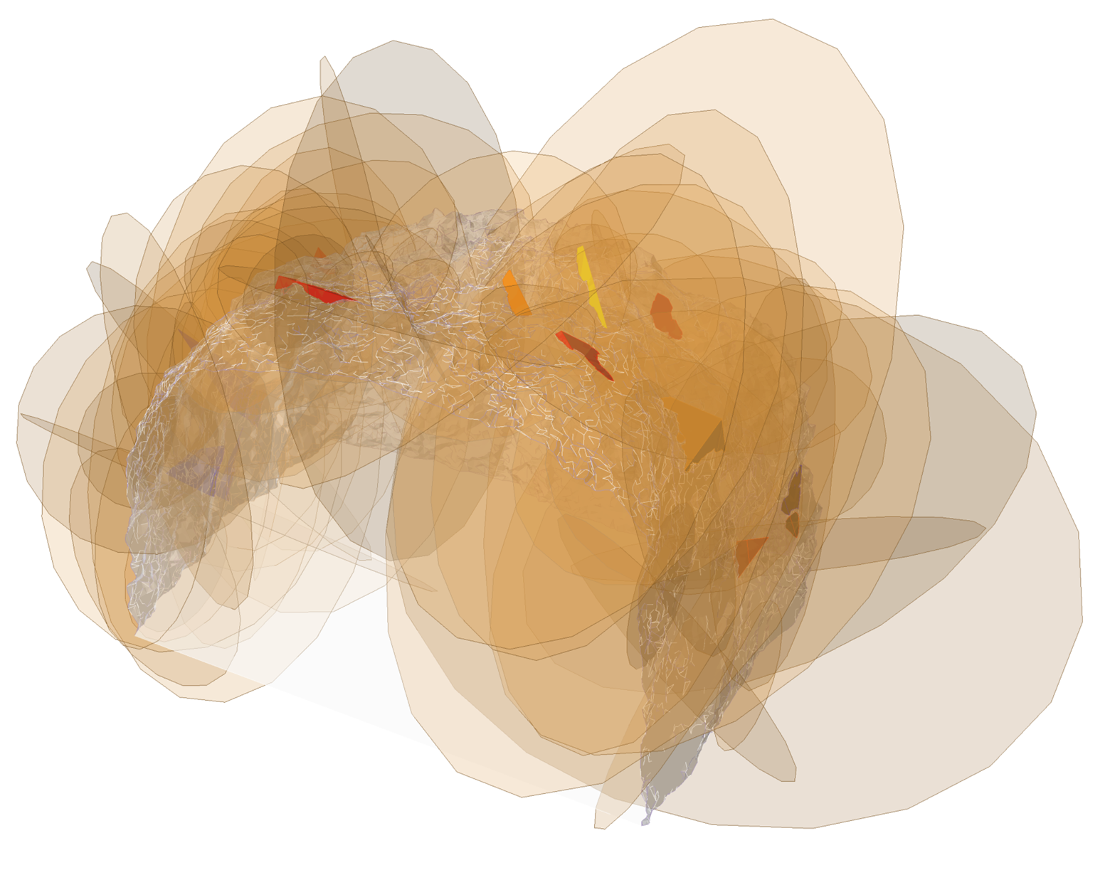
RocTunnel3 uses the available location and size data in the 3D excavation geometry and geologic structures to determine the intersection of structures in space that form blocks around the excavation. A factor of safety or a probability of failure is calculated for each block in a deterministic or probabilistic analysis, respectively.
Users can also take advantage of the staging capabilities in RocTunnel3. After all, a block is only important if it has a daylighting face, which can only come into existence through staged excavation.
While the as-built project can benefit from the hazard assessment insights provided by the 3D model in RocTunnel3, the model itself can also benefit from the real-world data it used in its construction to reconcile model with reality.
How can this benefit you?
- Modern tools like ShapeMetriX and RocTunnel3 have the capability to allow you to realistically assess underground hazards in rock excavations, to inform risk management and on-site practices.
- 3D model generation for underground applications is becoming more efficient and is more accessible, as common equipment such as cameras can be used for data acquisition.
- Leveraging the integration between ShapeMetriX and RocTunnel3 can help to facilitate a straightforward workflow.
More from Rocscience