Optimizing Speed and Precision: Hybrid Mesh in RS3
- Sina Moallemi, Geotechnical Product Manager
- David Ko, Geotechnical Project Manager
- Arsalan Jameei, Geomechanics FE Specialist
RS3 employs Finite Element Method for the analysis of geotechnical structures for civil and mining applications. When constructing a finite element model, meshing stands as a fundamental step. It entails the discretization of the domain into smaller elements, enabling the representation of complex shapes and structures. These discrete elements facilitate the numerical solution of partial differential equations for the approximation of physical quantities such as stress, strain, and displacement within each element.
Element Density: 4-Noded vs 10-Noded
The choice of element density imposes a direct impact on the accuracy of the result and computational efficiency. So does the type of element used to mesh the model. RS3 offers two types of elements; and they are 4-noded tetrahedron and 10-noded tetrahedron, representing different level of geometric/interpolation order. The first order 4-noded tetrahedron consists of nodes at each vertex, whereas the second order 10-noded tetrahedron consists of nodes at midpoints at every edge as well as at the vertices. Computationally, 4-noded and 10-noded elements employ linear shape function and quadratic shape function, respectively. The quadratic shape function employed by 10-noded elements allows for the capture of non-linear deformation and stress distribution within elements, providing a higher level of accuracy for, especially, complex models. Conversely, the linear shape function poses a certain degree of limitation to the result accuracy for the 4-noded elements. Furthermore, this limitation cannot be overcome by simply increasing the mesh density as the limitation originates from intrinsic method to solve the equation. However, just like the inverse correlating relationship the mesh density has with the computation efficiency for the price of higher accuracy, employing 10-noded elements costs a longer computation time.
In order to take the advantage of both types of finite element into the numerical analysis, RS3 offers a hybrid mesh system, which enables users to customize the region with different element types. This approach allows you to have a full control over which region(s) the RS3 engine to focus on computing the material behaviour with higher level of accuracy. You can now strategically position higher-order elements in areas with higher potential for failure, such as close to slopes. Conversely, linear elements can be employed in locations that are likely to be stable. This technique enables you to attain accurate results while minimizing computational costs.
Comparison Study
A comparison study was undertaken to evaluate the efficacy of three different meshing techniques, i.e. 4-noded, 10-noded, and mixed-noded (hybrid) tetrahedra elements. This study demonstrates the nuanced trade-offs associated with the adoption of diverse meshing techniques. Specifically, the focus is on the evaluation of the performance of the hybrid mesh in two critical aspects: computational efficiency and its result accuracy.
The numerical investigation was carried out with an open pit mine model, performing Shear Strength Reduction (SSR) analysis. This analysis method was chosen since the modelling result comparison can be performed based on quantitative measure of stability, given by Strength Reduction Factor (SRF), which is a comparable parameter to the Factor of Safety (FS). To ensure a rigorous validation process and avoid unwarranted assumptions about the correctness of the 10-noded mesh, an initial slope stability analysis was performed using Slide3, which applies 3D Limit Equilibrium Method to calculate FS and produce the corresponding sliding surface. The results obtained from Slide3 served as a baseline to verify the accuracy of the modelling solution generated by RS3.
The numerical simulation was repeated three times, each time (case) employing different meshing techniques, but uniformly applying an identical element distribution. The implementation of the hybrid mesh system was carried out in two-fold process:
- Defining the higher order region(s), in another word, allocating the region(s) to be meshed with 10-noded tetrahedra elements, followed by
- Applying Mixed 4-Noded and 10-Noded Tetrahedra meshing.
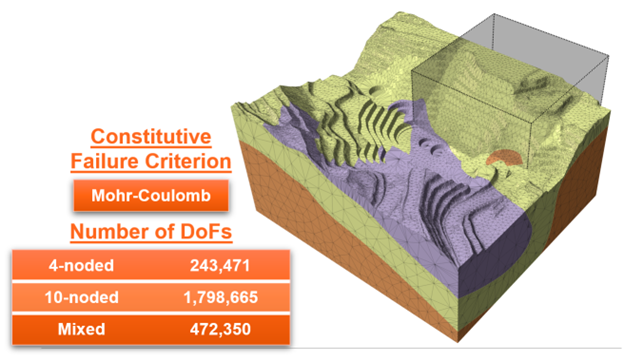
The model geometry used for this numerical exercise is shown in Figure 1. A higher order region defined for this exercise is represented by the grey box, wherein all elements located inside the region have 10 nodes. The total number of Degree of Freedom (DoF) of system varies with different meshing techniques.
Slide3 vs RS3 (10-noded)
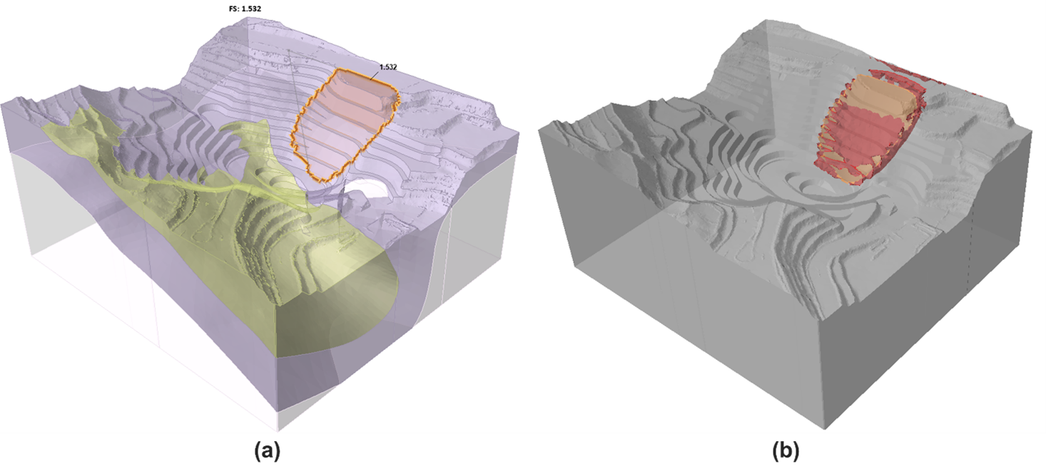
The outcomes of the slope stability analysis from both Slide3 and RS3 (10-noded case) demonstrated close congruence, not only in terms of stability parameters but also in the generated sliding surface. The critical Strength Reduction Factor (SRF) computed with the 10-noded case, at 1.56, exhibits a minimal discrepancy of only -0.03 when compared to the Factor of Safety (FS) computed with Slide3. This quantitative proximity could gain meaningful significance due to the well-aligned potential sliding surfaces, as illustrated in Figure 2.
Table 1 - Critical SRF computed with RS3 and FS computed with Slide 3
Method |
Critical SRF/ FS |
RS3 (SSR; 10-Noded;) |
1.56 |
Slide3 (Spencer) |
1.53 |
Comparison between Meshing Techniques
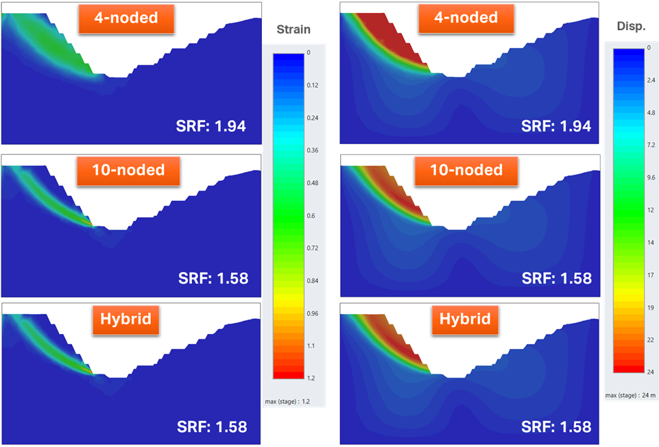
Table 2 shows a summary of the model setting, computational efficiency indicators, and results for each case as well as the Limit Equilibrium Analysis result from Slide3. As previously mentioned, an identical number of elements were utilized across all three cases. Nevertheless, the Shear Strength Reduction (SSR) analysis conducted with 4-noded and 10-noded element types revealed an approximately 20% difference in Critical Strength Reduction Factor (SRF). This variance stems from the limited capability of the 4-noded element to accurately simulate the mechanical response of materials under high deformation or stress gradients, as evidenced by the misalignment in displacement and shear strain contour plots in Figure 3. In return, the computational time for the 4-noded case was notably faster, completing in less than 0.125 times the duration of the 10-noded case. On the other hand, employing the hybrid mesh technique resulted in an analysis time only twice that of the 4-noded case. At the same time, the hybrid mesh case achieved a critical SRF identical to that of the 10-noded case, as well as matching mechanical behavior.
Table 2 - Modelling Results for Studied Cases
Case |
Number of Elements |
Number of DoFs | Number of SSR Iterations |
Total Time |
Normalized Time | Critical SRF |
4-noded |
412,470 |
243,471 | 9 |
23m : 50s |
1 |
1.92 |
10-noded |
412,470 |
1,798,665 | 7 |
3h : 13m : 50s |
8.13 |
1.56 |
Hybrid |
412,470 |
472,350 | 7 |
47m : 54s |
2.01 |
1.56 |
Slide3 (Spencer) |
- |
- | - |
- |
- |
1.53 |
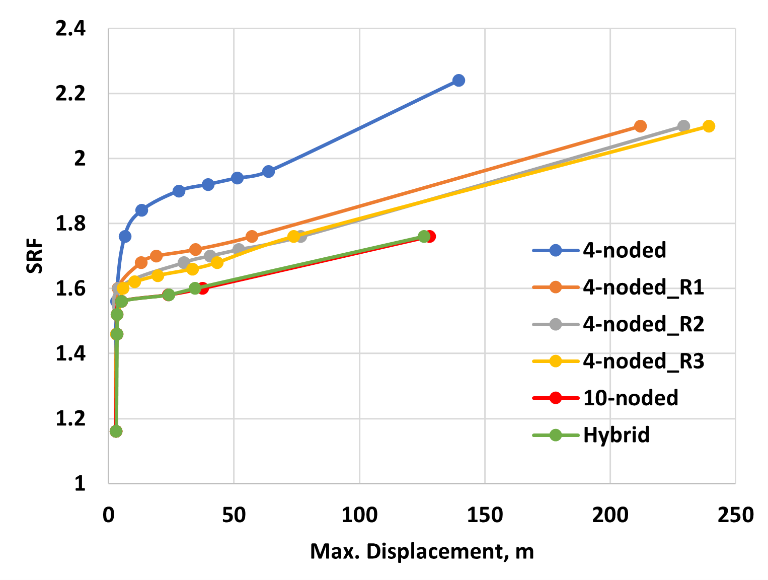
This numerical exercise was carried out a step further to assess the feasibility of achieving a comparable level of accuracy by improving the mesh density of 4-noded tetrahedral elements, akin to the precision exhibited by the hybrid case in comparison to the 10-noded case. However, despite surpassing the hybrid case in both degrees of freedom (DoFs) and total computation time, the 4-noded case models fall short of attaining the same level of accuracy as the hybrid configuration. Moreover, the trials reveal that the sensitivity of material behavior, as quantified by critical SRF and maximum displacement, plateaus in response to the increasing number of elements (See Figure 4). This observation indicates that further densification of elements becomes redundant.
Table 2 - Modelling Results for Studied Cases
Case |
Number of Elements |
Number of DoFs | Number of SSR Iterations |
Total Time |
Normalized Time | Critical SRF |
4-noded_R1 |
1,154,575 |
617,580 | 8 |
2h: 06m: 44s |
5.32 |
1.7 |
4-noded_R2 |
1,866,835 |
980,742 | 8 |
2h: 51m: 15s |
7.19 |
1.68 |
4-noded_R3 |
3,097,546 |
1,603,167 | 9 |
5h: 52m: 07s |
14.77 |
1.64 |
Concluding Remarks
This study’s findings suggest that employing hybrid mesh technique offers the benefit of achieving high result accuracy with a significant improvement in computational efficiency. Moreover, this balanced approach outperforms the limitations observed in the denser 4-noded case, emphasizing the practical advantages of adopting hybrid mesh strategies for effective geotechnical modelling.