One Ecosystem, One Workflow: Seamless 3D Tunnel Analysis with ShapeMetriX and RocTunnel3
- Dr Grace Huang, Geotechnical Product Manager
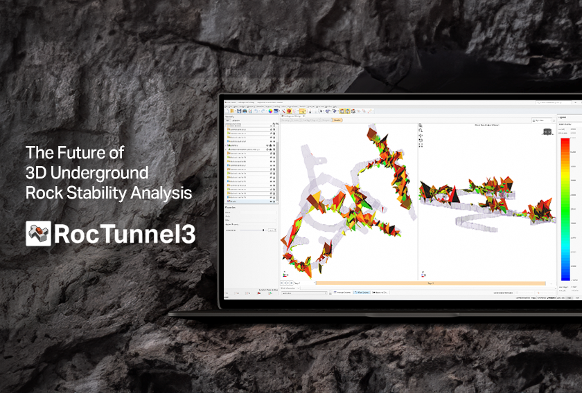
RocTunnel3 is one of our latest, state-of-the-art 3D block modelling and stability analysis tools for underground excavations. It brings the power of true three-dimensional kinematic analysis to complex tunnel geometries – enabling engineers to model excavation stages, interpret block failure mechanisms, and apply support strategies with greater confidence.
Built to integrate seamlessly with ShapeMetriX, RocTunnel3 leverages 3GSM’s photogrammetry and LiDAR data to import precise as-built geometries and structural mapping directly into its modelling environment. This guide outlines a step-by-step workflow for importing ShapeMetriX field data into RocTunnel3 to build geologically sound 3D excavation models. This workflow enables geotechnical engineers to realistically model the as-built excavation, mapped joints, and excavation stages – helping forecast block failures in 3D, manage risks, and support informed decisions on-site.
What can RocTunnel3 import from ShapeMetriX?
- The as-built excavation geometry from different stages (.obj format), as obtained from photogrammetry or LiDAR.
- Data of geological structures mapped in ShapeMetriX, including the dip, dip direction, locations (x, y, z), and apparent size (.dips8 format).
- Large geological structures in a geometry format (e.g., .obj or .dxf), representing mapped discontinuities that are extrapolated in size. These are useful for forecasting failures and could be smooth or rough.
Workflow
Project Settings
Any 3D modelling process starts in Project Settings. Here, it’s important to define the working unit system and the number of stages for analysis, which would depend on the sequence of excavation, loading, and support. The user is also required to define a Design Factor of Safety – any 3D block that is geometrically removable from the excavation and has a factor of safety lower than the Design Factor of Safety would be marked as a “failed” block.
Geometry
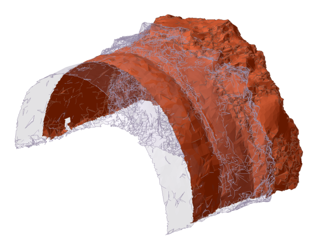
The 3D excavation model generated in ShapeMetriX from photogrammetry or LiDAR data can be imported into RocTunnel3 as a .obj file. Geometry formats accepted by all Rocscience 3D programs are listed here, including .obj, .dxf, and others. Additionally, you can add surfaces from point data to create triangulated geometries directly within the software.
An excavation may be scanned via remote sensing multiple times throughout its excavation sequence, resulting in multiple geometries, each representing a different stage of the excavation. The multiple geometries may be batch imported into RocTunnel3. Each geometry would be in the form of an excavation surface, but built-in tools in RocTunnel3 could help to further process defects and generate a volume model that’s required for 3D analysis.
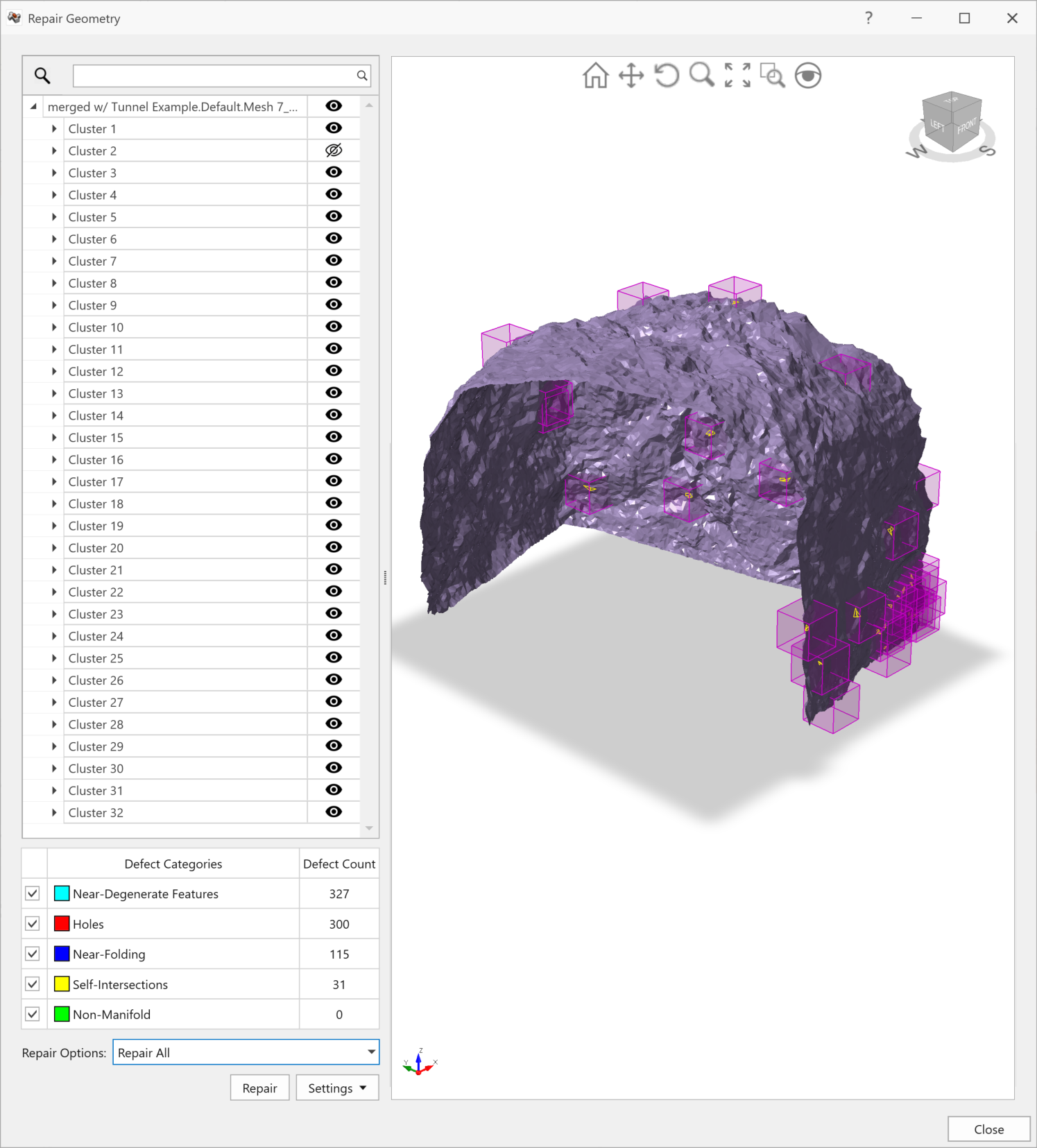
Defects are inevitable in raw geometries and must be repaired to prevent computational interferences. In excavations, defects may result from incomplete remote sensing data or geometry overlap at the interface of different excavation stages. Defects should be repaired because the mesh quality can affect the calculation of joint intersections and blocks. The following repair tools in RocTunnel3 are useful for achieving a single contiguous excavation surface:
- Merge – Collapses overlaps
- Retriangulate – Retriangulates mesh triangles with poor aspect ratios
- Ungroup non-manifold – For specialized repairing of non-manifolds or t-intersections; mesh elements are ungrouped at non-manifolds to result in a main excavation surface and other undesired geometry elements; discard any undesired geometry elements that are not on the main excavation surface
- Ungroup disjoint – For specialized repairing of mesh elements that are adjacent but discontiguous. After ungrouping, discard any undesired geometry elements that are not on the main excavation surface
- Repair – For defect diagnosis and overall repair; recommended for use in cases of few defects or after specialized repair.
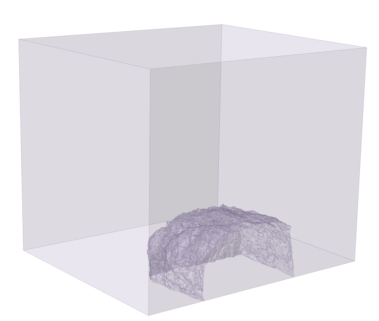
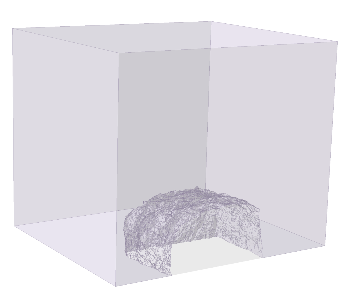
Once the excavation surfaces are defect free, create an External box and perform a Divide All. The External is a volume that represents the bounding rock mass. The Divide All operation divides the External box at the excavation surfaces (interfaces), creating a volume for each excavation stage and the surrounding rock mass. For a successful Divide All, the External box must fully intersect the excavation surfaces at the boundaries.
Rock Mass Materials and Excavations
Different rock mass properties (e.g., unit weight, groundwater characteristics) may be defined and then assigned to rock mass volumes. Note that an excavation is equivalent to a “No Material” property. For staged excavation, select the stage at which an excavation is anticipated and toggle the material property of the target excavation volume to “No Material”.
Structures
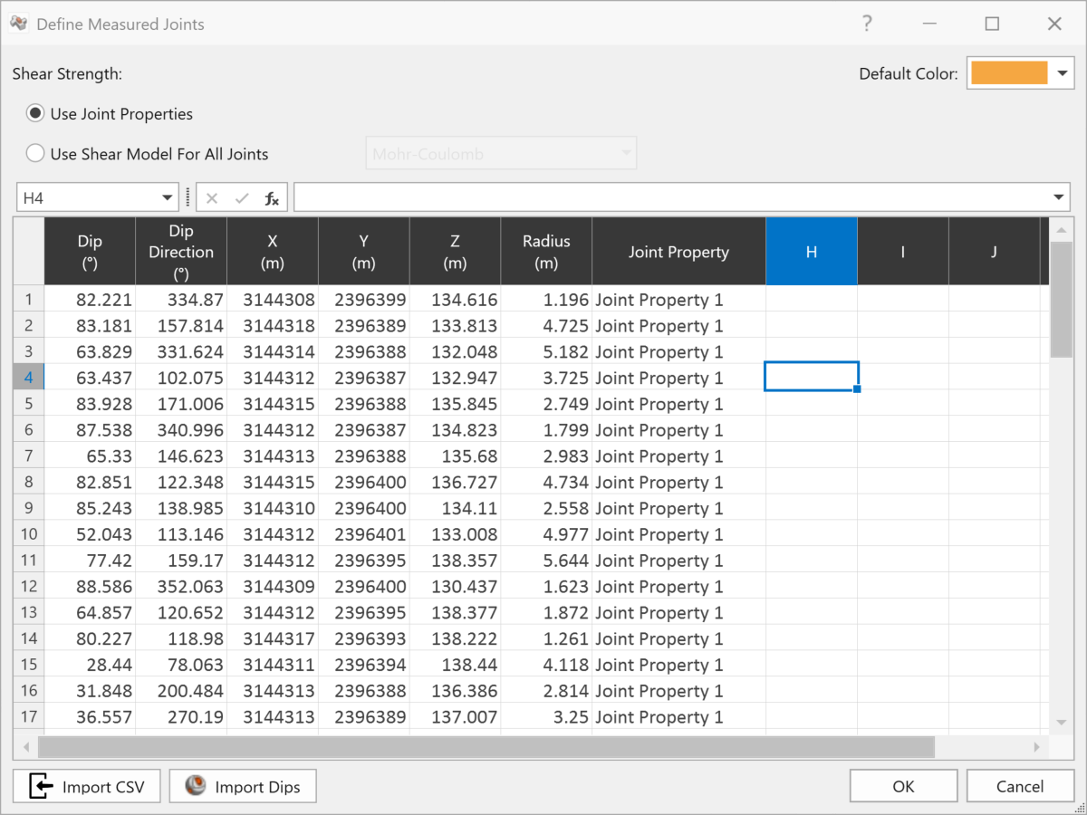
Structures in RocTunnel3 can be defined from Measured Joints or surface geometries, both of which are compatible with ShapeMetriX. Structures mapped in ShapeMetriX have data for the dip, dip direction, locations (x, y, z), and apparent size – these “Measured Joints” can be saved in a .dips8 file that can be directly imported into RocTunnel3.
As the Measured Joints are stored in a DIPS file, they can also be opened in DIPS for assessment of joint sets, joint statistics, and kinematics – all of which are analyses complementary to RocTunnel3 3D block stability assessment.
Structures mapped in ShapeMetriX may also be extrapolated in size and exported to RocTunnel3 in a .dxf format. These structures are essentially imported into RocTunnel3 like any other geometry file and then assigned as joint surfaces with an appropriate shear strength property.

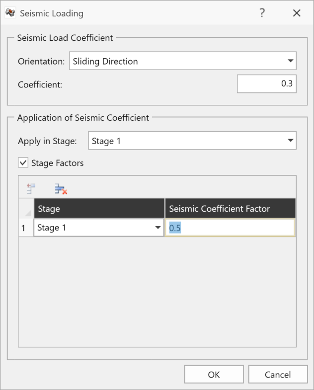
Loading and Support
Any external loading (e.g., pseudo-static earthquake loading), shotcrete, and bolts can be applied in stages. A seismic example is shown in the following figure.
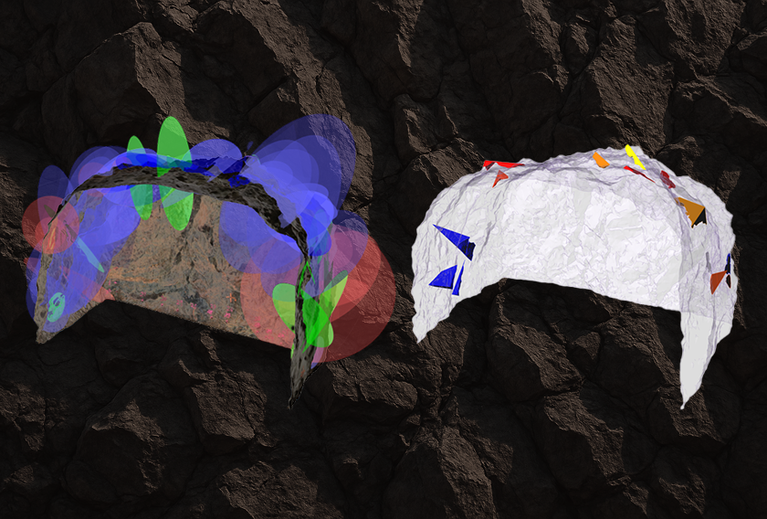
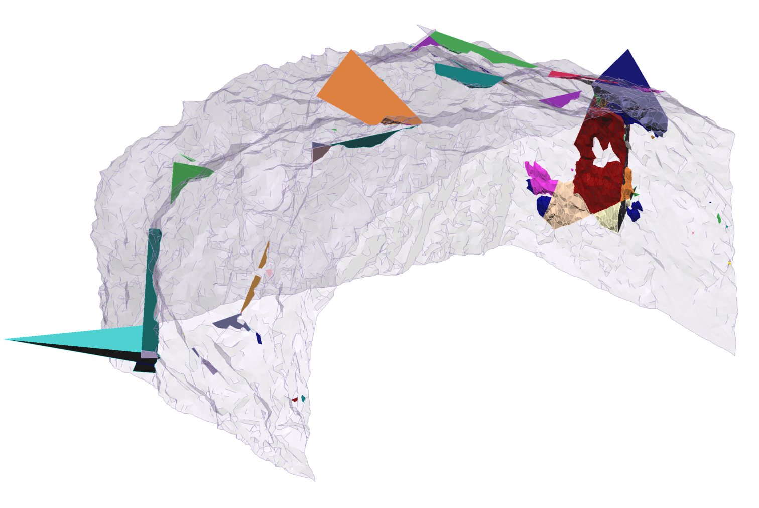
Compute Blocks and Kinematics
Block and kinematics computations are performed to first obtain blocks from the intersection of joints with the geology and then the factor of safety of each block, respectively. Results are mapped onto the excavation, so that users can see where there are daylighting blocks and which blocks do not meet the Design Factor of Safety.

Key Takeaways
RocTunnel3 and ShapeMetriX together offer a streamlined, technically grounded path from field mapping to block stability analysis. Whether you’re visualizing excavation stages, integrating joint data, or simulating potential failures in 3D, this workflow makes advanced tunnel modelling more accessible and more actionable.
Do you want to see how RocTunnel3’s full feature set fits into your tunnel design workflows?
Rocscience continues to expand its ecosystem with tools and data sources that reflect how engineers work in the field and underground. If you're working with tunnel projects that demand realistic geometry and risk-aware design, this integration is worth exploring.
Start your free trial today!