Methodological Aspects of 3D Numerical Analysis on Cavern Complex in Difficult Conditions
by Ing. Cristiano Bertello (GEODATA Engineering S.p.A.)
In recent years there has been a remarkable development of methodologies and calculation tools to assist designers of underground projects to adopt more effective and conscious solutions. Major works such as hydroelectric plants, especially because of their strategic importance, certainly fall within the spectrum of application of these tools.
This case study presents the most relevant aspects of the geomechanical analysis of a cavern complex belonging to a hydroelectric repumping plant.
Introduction and General Aspects
The main components that constitute the central part of the generation circuit (Figure 1) are:
1. Powerhouse (PH, cavern housing turbines where water is conveyed into turbines to convert kinetic energy into electrical energy);
2. Transformer Hall (TFH, where voltage and electric power are varied).
3. Tunnels connecting the main caverns and access/construction tunnels: Busbar tunnels 1 and 2 (BST1 and BST2), Main Access Tunnel (MAT), Old Main Access Tunnel (OLD MAT);
4. Pilot tunnels 1 and 2 (respectively connected to the northern wall of the Powerhouse (PT1) and of the Transformer Hall (PT2);
5. Secondary access tunnels (Adits).
Geological and Geomechanical Context
The geological context is characterized by:
- Competent basaltic matrix (Bs-strong);
- Fractured basalt (Bs-weak);
- Inclined layers of pyroclastic material (Pyr);
- Fault systems.
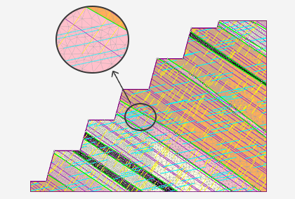
From boreholes data and surveys on excavation exposed faces it was generated using the dedicated tool Leapfrog Works® a three-dimensional geological model. The geological information deriving from the three-dimensional geological analysis is subsequently managed from the geometric point of view by a 3D modelling code, to be finally properly imported into the finite element analysis code RS3. At the same time, the excavation phases to be simulated are defined through the removal of groups of elements previously defined.
Hydrojacking tests have been carried out at depths that cover the entire sector of the cavern complex (from approximately -290m to -520m), by means of which it was possible to determine the design in-situ stress.
FEM 3D Analysis using RS3 and Support Systems Verification
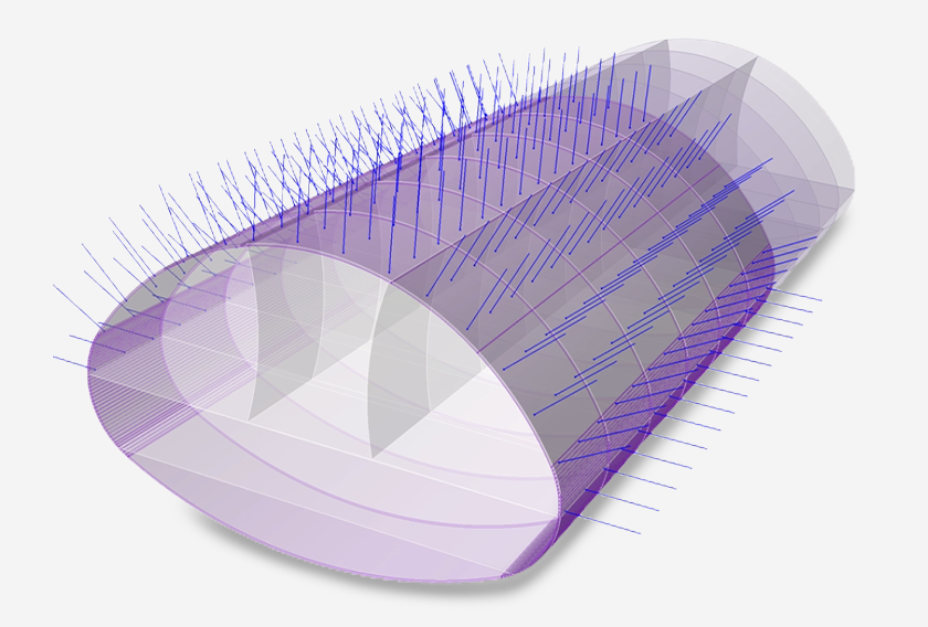
Support systems considered in the FEM model are:
1. Shotcrete layer class C28/35 with wire mesh (thickness 35cm);
2. Rock dowels;
3. 10-strand tendons.
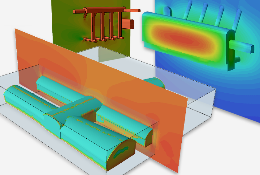
The results first show the extent of the plastic zone between the caverns and between the BSTs.
The cavern that presents the most critical issues, mainly because of the vicinity with the major fault system, is the PH.
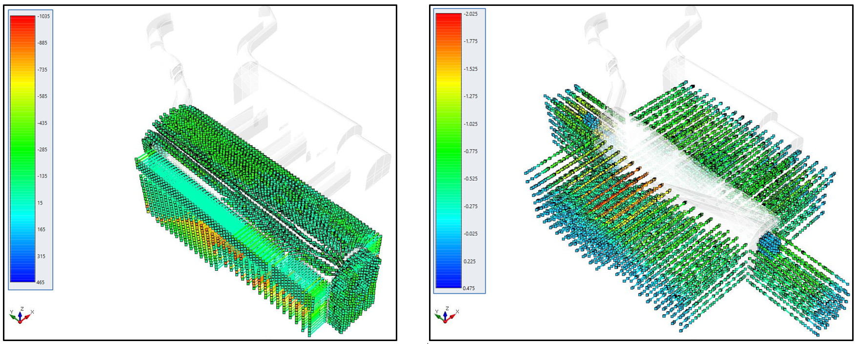
The axial stresses on rock dowels are reported in the following figure, as well as strand tendons' axial forces that show the same trend.
Conclusions
In conclusion, it was shown how 3D finite element analysis can represent a valid tool for the accurate determination of the critical areas of the project and the appropriate choice of support systems. Fundamental is the work during the setting up of the model, with special attention to the correct generation of the different lithologies.
The results presented in this document have been used to understand the behaviour of the complex, confirm the assumptions and analyses obtained by other parties, and correctly design the support systems.
Note: This case study is based on the technical paper by Ing. Cristiano Bertello of GEODATA Engineering S.p.A.