Latest Features in UnWedge
UnWedge is a dynamic 3D stability and analysis program designed to help you with your most challenging underground wedge analysis problems. UnWedge can be used for excavations, mining and tunneling.
Stay up to date with the latest features and integrations that you can incorporate into your geotechnical projects.
September 2021
Improved Bolt Patterns and Vertical Shaft Handling
With the new UnWedge release coming this late July, the support design process is getting even better. Users adding bolt patterns and spot bolts to their design now have more options for defining the geometry of their bolts. Users can now input the local trend and plunge angles manually when adding bolts. This expansion of design options allows practitioners more precise control over the design of their supports and as well as a speedier overall design process.
In addition to these new support design options, an exciting new feature has been added for defining the geometry of vertical shafts. As mentioned previously, models are created in UnWedge by defining a 2D section and extruding this along the tunnel axis. In the case of vertical shafts, this process has been made even better with the new option to apply a ground surface to the top end/roof of the shaft. The addition of this ground surface above the roof of the shaft provides a realistic boundary for wedge and support extents. This option has been enhanced even further as well with the option to define a water surface along the height of the shaft.
Comparative analysis: Vertical Shaft in UnWedge and RS3
While UnWedge on its own is a fantastic LEM program for analyzing wedge stability in rock mass excavations, performing a fully comprehensive analysis of any underground excavation often means using multiple analysis methods to verify your critical failure results. A great companion tool for performing such analyses is the 3D FEM program RS3. Finite Element programs like RS3 allow users to consider other factors beyond wedge stability such as displacement and joint stiffness when analyzing the stability of a model. In the following example, we perform such a comparative analysis by first using UnWedge to analyze a vertical shaft with a circular cross-section, and then comparing the results in RS3.
UnWedge Analysis
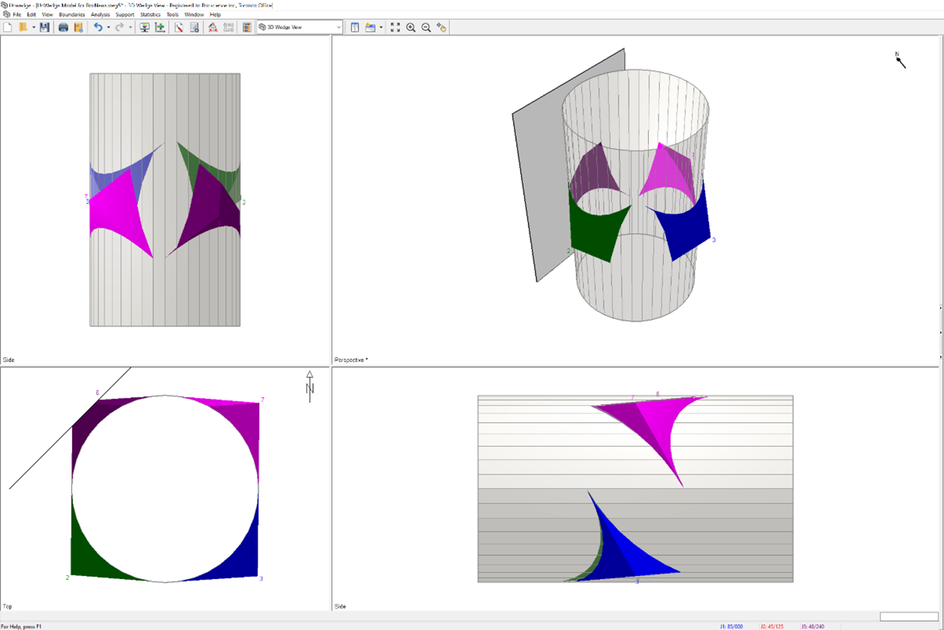
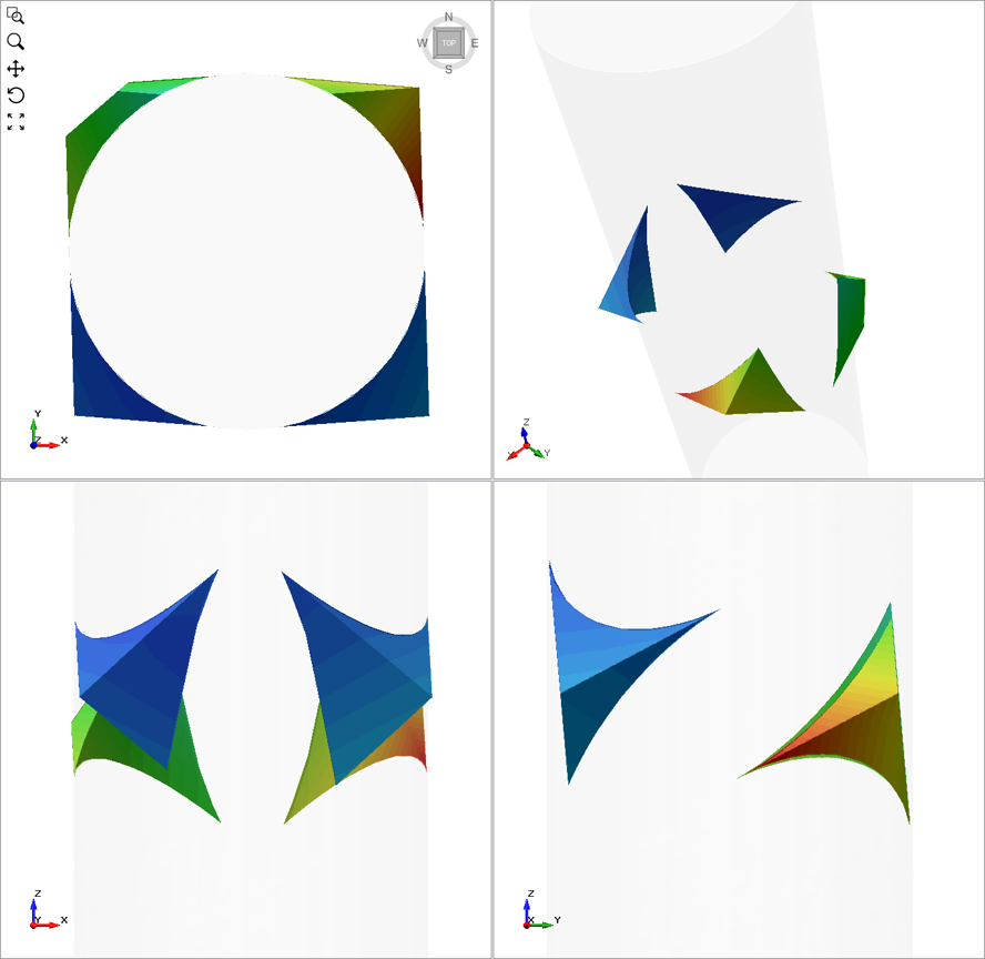
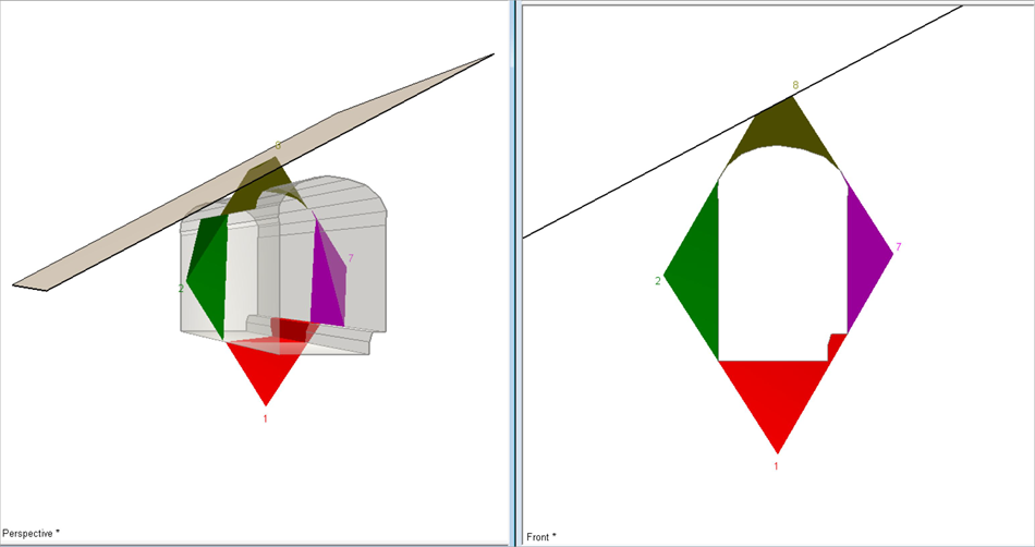
The UnWedge model shown below consists of a vertical shaft with a tunnel trend of 0 degrees, a plunge of 90 degrees, and a circular cross-section with a diameter of 6m.
A wedge analysis using UnWedge is suitable for this case since we are dealing with an underground excavation in rock containing intersecting structural discontinuities. These discontinuities are assumed to possess significantly lower shear strength and negligible tensile strength, compared to the surrounding intact rock mass. The three joint orientations that make up the resultant wedges have Dip/Dip Directions = 85/0, 45/125, 48/240 deg, respectively. The joints’ shear strength follows a Mohr-Coulomb model, with a friction angle = 30 deg, and zero cohesion and tensile strength.
Four perimeter wedges are formed along the shaft. Here, we will only look at a 10m-long segment of the shaft and skip the computation of the end wedges (i.e., roof and floor wedges). A truncation surface is added (trend = 45 deg) at an offset of approximately 0.54 m away from the tunnel. The truncation surface acts as a realistic boundary (i.e., discontinuity, wall, etc.) for the North West wedge, by reducing its apex and overall volume.
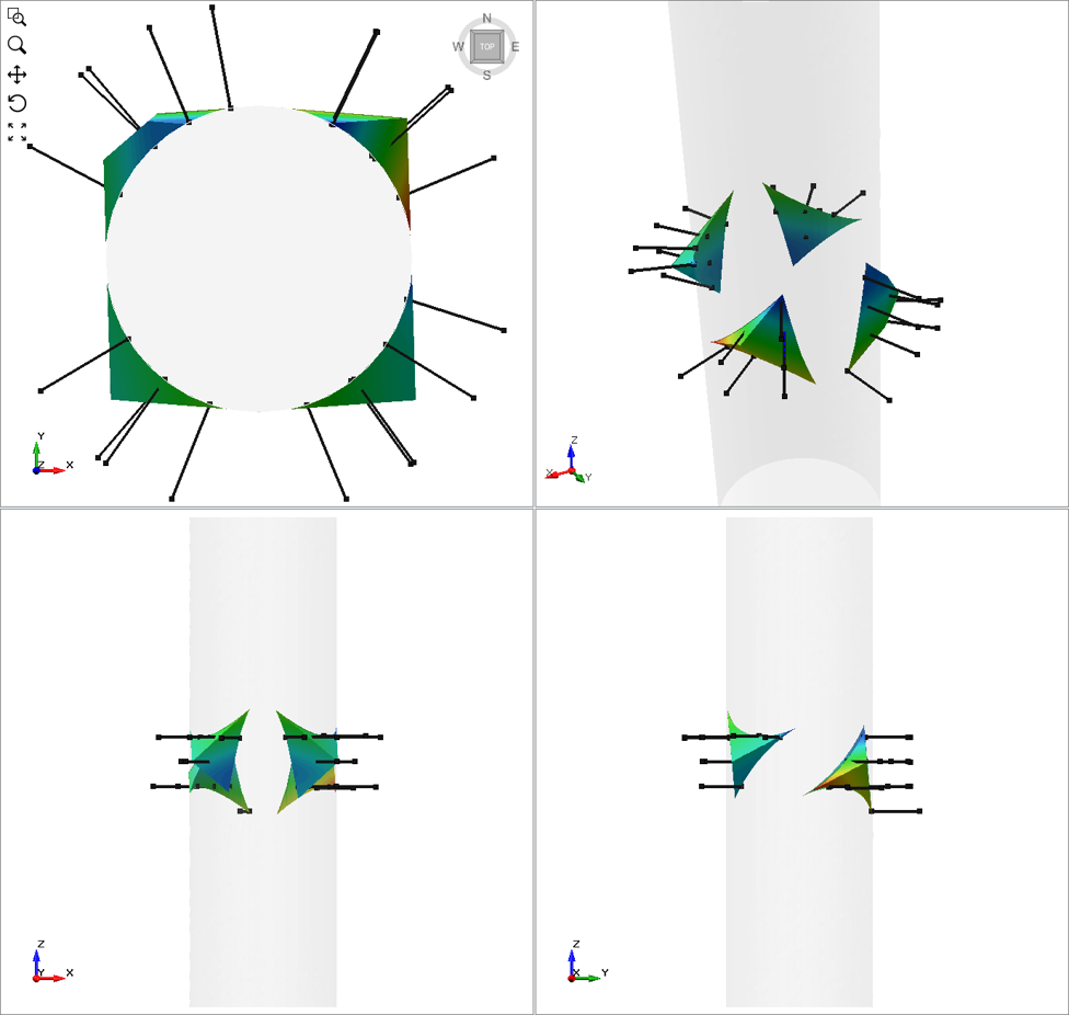
In order to achieve a Factor of Safety of at least 1.5 for the shaft design, we will stabilize the wedges with mechanically anchored rock bolts. The bolt has a Tensile Capacity, Plate Capacity, and Anchor Capacity = 0.1 MN and Shear Strength = 0.01 MN. The bolts are 1.5 m in length which exceeds the maximum apex height of the perimeter wedges. Since these wedges can technically form anywhere spatially along the height of the shaft, we design a bolt pattern spaced at 1m by 1m to ensure an adequate number of intersecting bolts per wedge, regardless of the spatial location.
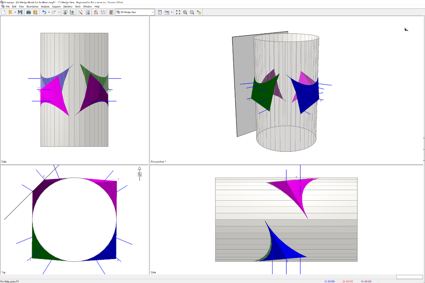
After placing the supports, we see that the Factor of Safety is well above 1.5 for all four perimeter wedges.
RS3 Analysis
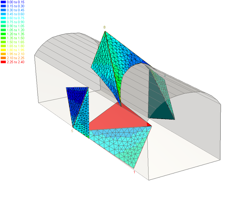
To verify these results, we then performed a non-shear strength reduction (SSR) analysis of the same shaft in RS3. To do this, the excavation and joint geometries were imported from UnWedge into the RS3 program. The rock mass was modelled as elastic and the joint strength was modelled as plastic to explicitly model only wedge failure mechanisms. The joints had the same Mohr-Coulomb strength parameters as the UnWedge example as well as the same unit weight (0.027 MN/m3). Gravitational in situ stress was modelled in UnWedge. Finally, a very low horizontal stress ratio of 0.01 was applied to minimize clamping effects from the stress state around the shaft.
The SSR analysis showed that the factor of safety from RS3 can exactly match UnWedge results under certain joint stiffness parameters (primarily shear stiffness). This joint stiffness had the most notable impact on results, where stiff joints increase the factor of safety and soft joints reduce it. Generally, high differences (orders of magnitude changes) are required to see significant differences in results.
What we learn from this observation is that while stiffness (deformation) properties are not considered in UnWedge, that does not mean that they are unimportant or do not influence behaviour. What this specifically means for UnWedge users is that to mimic rigid block failure in RS3, it appears that the ratio of rock Young’s modulus to joint stiffness, particularly shear stiffness, must be high.
In addition to the learnings regarding stiffness, RS3 was also able to show the total displacement results of the wedges (shown in the previous image) as well as the resulting total displacement when supports are applied (shown above) which verifies the results found in UnWedge.
June 2020
Expanded Reinforcement Library
UnWedge is a 3D stability analysis program used to determine the stability of rock wedges formed by the intersection of structural discontinuities. The program’s ability to calculate the factor of safety for potentially unstable wedges and determine support requirements for projects makes it a critical tool for geotechnical engineers that work with tunnels, underground excavations, and caverns.
As part of the continuing effort to make designing support solutions simpler, a new list of Common Support Types has been added to the program. Rocscience has partnered with DEXTRA to provide a list of their various products to the Reinforcement library in the Bolt Properties dialog. Users can simply select the product from the list and the manufacturer's specifications for the bolt are automatically filled in, making for faster and more accurate analysis.
November 2019
Multiple End-Wedge Support Patterns and Underground Truncation Surface
The new UnWedge features the addition of multiple end-wedge support patterns and truncated underground wedges with support.
Users can now specify multiple end-wedge support patterns in the End Support Designer using the Add Bolt Pattern option. Bolt patterns can be added, deleted, or edited.
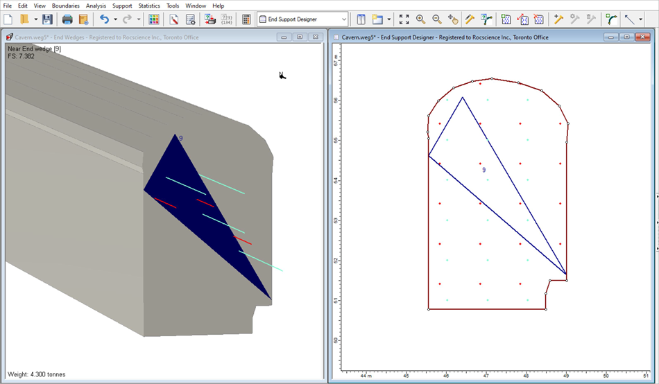
A new Add Truncation Surface option has also been added to allow users to limit the boundary within which wedges can be formed without altering the ground surface. This can result in a truncated wedge or no wedge being formed under the truncation surface.
This feature is especially useful for modeling supports since supports cannot protrude through the ground surface but can protrude through the truncated surface. Any length of support outside the truncated surface does not carry any load, thereby limiting its effective bond length.
The Ground/Truncated Surface feature can also be used to define the piezometric surface when modeling water pressure.
Learn UnWedge
Explore the UnWedge user guide for in-depth instructions on how to use the program and visit our library of learning resources, including case studies, past webinars, and articles, designed to expand your geotechnical knowledge and help you get the most out of your analysis.