Integrating Slide2 and RS2 in the Design of Embankment Dam Stabilization Works
- Dan Simpson, Technical Director at CGL (Card Geotechnics Limited)
- Ian Williams, Rocscience Representative, UK & Ireland
Integrating geotechnical software tools like Slide2 and RS2 is redefining how engineers approach dam safety and stabilization. For a recent project in the UK, these programs worked in tandem - Slide2 provided rapid limit equilibrium analysis and seepage modelling, while RS2 delivered detailed finite element validation. This seamless integration enabled the design team to optimize pile and anchor layouts efficiently, cross-check results, and ensure a robust, safety-focused solution.
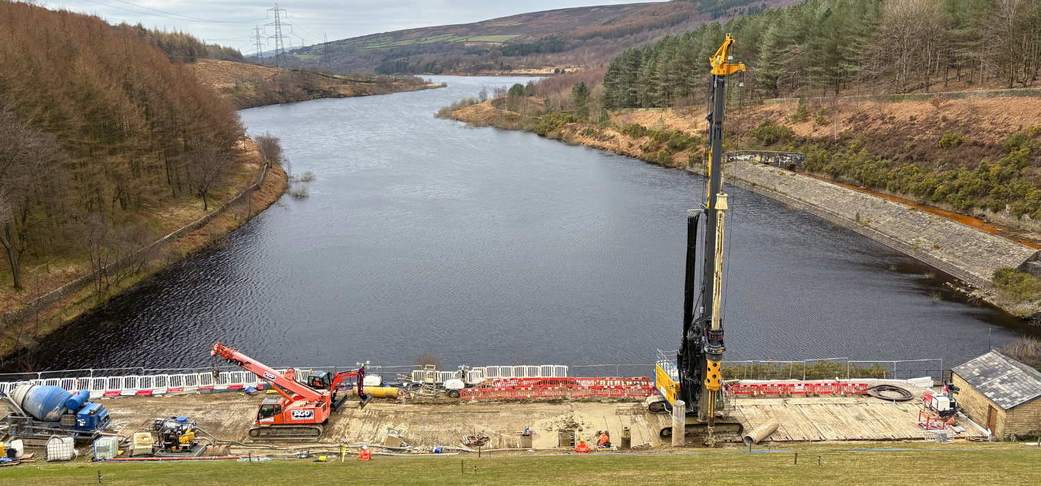
CGL recently completed the design of 56 piles and 54 ground anchors, with the goal of improving the overall stability of an embankment dam in Derbyshire, UK. The dam comprises of an earth fill embankment with a puddle clay core/cut off. It is approximately 34 m high and 270 m long. CGL was commissioned by specialist geotechnical contractor Keller to provide the detailed design of the piles and ground anchors. The reservoir is currently being kept at 4 m below the Top Water Level as a temporary safety measure until the piles and anchors are installed, after which the reservoir will operate at its Top Water Level with an adequate factor of safety.
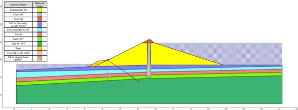
A section through the embankment showing the lines of proposed piles and ground anchors is presented on Figure 1.
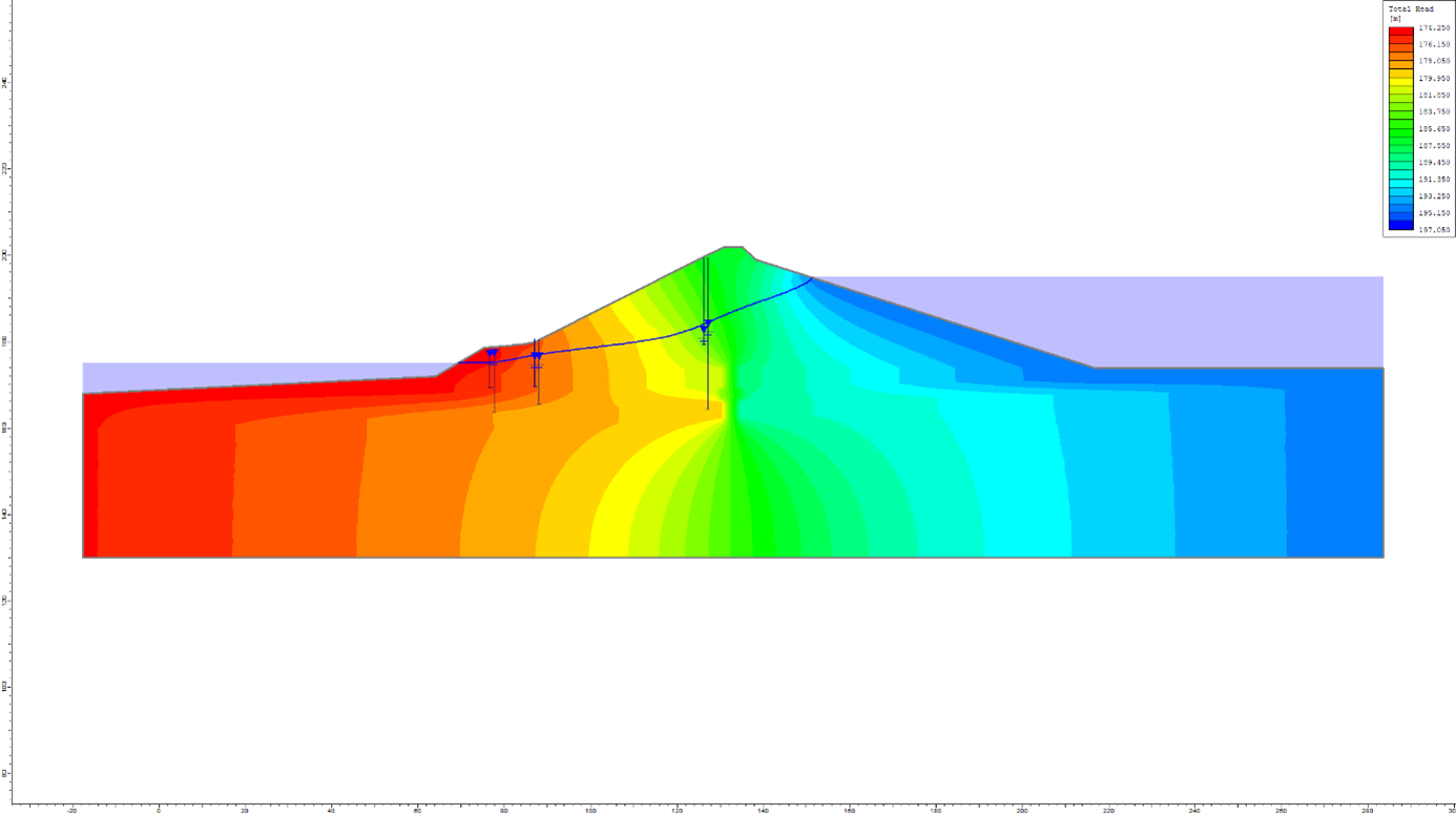
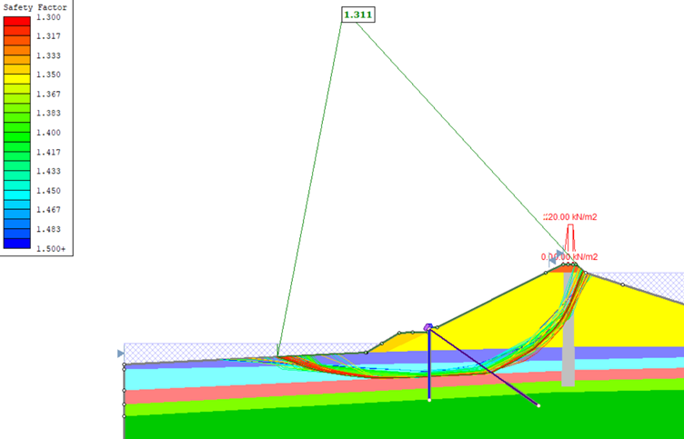
Slide2 was utilized to evaluate the prevailing stability of the embankment dam and study the sensitivity of the factor of safety to geometric controls and geotechnical parameters. Additionally, Slide2’s inbuilt finite element seepage analysis capabilities were used to calibrate the permeability values for the soil strata represented in the model and approximate the groundwater regime within the embankment as determined by ground investigation monitoring data. The piezometric elevations calculated by Slide2 are compared with the maximum recorded values in Figure 2.
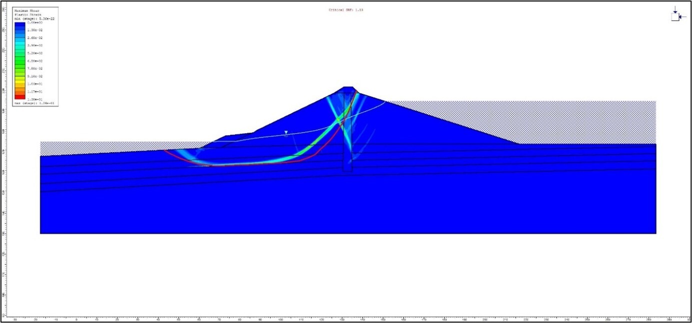
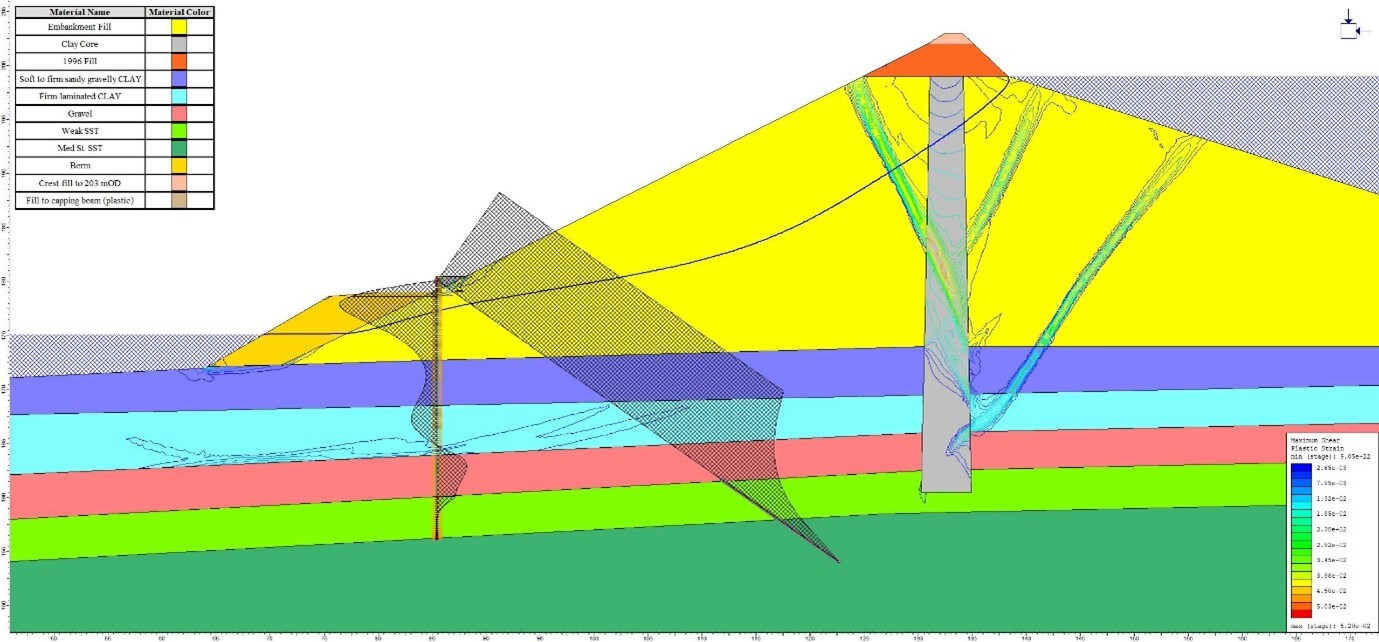
To verify the results of the Slide2 stability analyses for the dam in its existing condition, a series of shear strength reduction (SSR) analyses were performed using RS2. The strength reduction factor (SRF) values determined by the RS2 analyses compared well with the corresponding limit equilibrium Morgenstern-Price factor of safety (FoS) values established using Slide2 – the factor of safety given by Slide2 was 1.11 and the strength reduction factor given by RS2 was 1.13.
The results of the RS2 shear strength reduction analysis are summarized in Figure 3, where contours of maximum plastic shear strain at failure show the slip surface. Figure 3 also shows that the Morgenstern-Price critical slip surface determined by Slide2 (the red line) compares favorably with the slip surface determined by RS2. In both models, the failure surface passes along the base of a layer of relatively weak laminated clay.
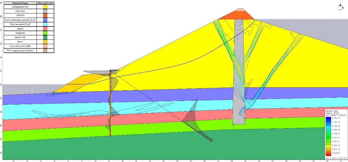
Once the existing stability and seepage regime were adequately understood, the effects of introducing the reinforcing elements comprising piles and ground anchors were modelled within Slide2 – these models also utilized the porewater pressures calculated using Slide2’s finite element seepage analysis. Following discussion with the piling contractor regarding rig access to the toe of the dam, it was established that due to the size of plant that could access the location, the maximum pile diameter that could be installed was 660/600mm (cased/uncased). The spacings of the pile and ground anchor elements were optimized within Slide2 to efficiently establish the resistance required to provide the required long-term factor of safety for the stabilized dam (Figure 4 and Figure 5).
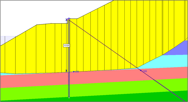
Pile and anchor forces were then checked using RS2. In all cases the pile and anchor forces calculated by RS2 were less than the values modelled in Slide2. This provided confidence in the Slide2 results, which were taken forward to the elemental design of the piles and ground anchors. The RS2 model was also used to calculate the pile/anchor forces and deflections at working load (SLS) – see examples on Figure 6 to Figure 8.

In summary, the final layout of the piles comprised of cased and augured 660mm/600mm diameter piles spaced at up to 1.2m centres and up to 24m deep. The ground anchors utilised were Keller’s proprietary Single Bore Multiple Anchor system comprising eight strand ground anchors up to 48m long anchored into medium strong sandstone bedrock. A 1.85m deep by 0.85m wide capping beam was designed to the tie the anchors and piles together at the head.
The integration of Slide2 and RS2 on this project is a great example of the practical benefits of combining LEM and FEM analysis. Slide2 enabled quick stability assessments and seepage calibration, while RS2 offered detailed validation of slip surfaces and pile/anchor behaviour. Seamless data transfer between the programs reduced duplication and ensured consistency, streamlining the design process. This approach not only enhances safety verification, but reduces iterations, and delivers more cost-effective solutions for stabilization projects.