Dynamic Compaction: The Latest Ground Improvement Method in Settle3
- Ali Chaudhry, Geotechnical Project Manager at Rocscience
Settle3 continues to evolve with the complex challenges engineers bring to it. Over the years, we’ve introduced Vibrocompaction, Stone Columns and Soil Replacement, offering users multiple ways to strengthen weak ground in their models. In the latest version, these capabilities are expanding further with the addition of Dynamic Compaction as the latest ground improvement option.
What is Dynamic Compaction?
Dynamic compaction is a ground improvement technique where a heavy tamper, typically ranging from 5 to 40 tonnes, is repeatedly dropped from heights between 10 and 40 meters in a systematic grid pattern. Each impact sends stress waves through the subsurface, collapsing voids, re-arranging particles, and driving densification to depths up to 10m. After the main high energy drops, engineers commonly apply a lighter ironing pass to densify the loosened soil in the impact craters, leaving a uniformly compacted working surface.
Modelling Dynamic Compaction in Settle3
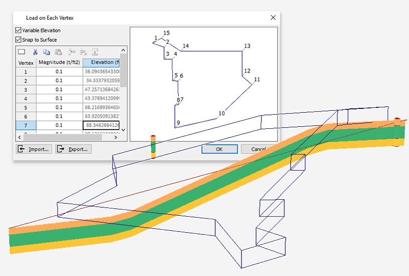
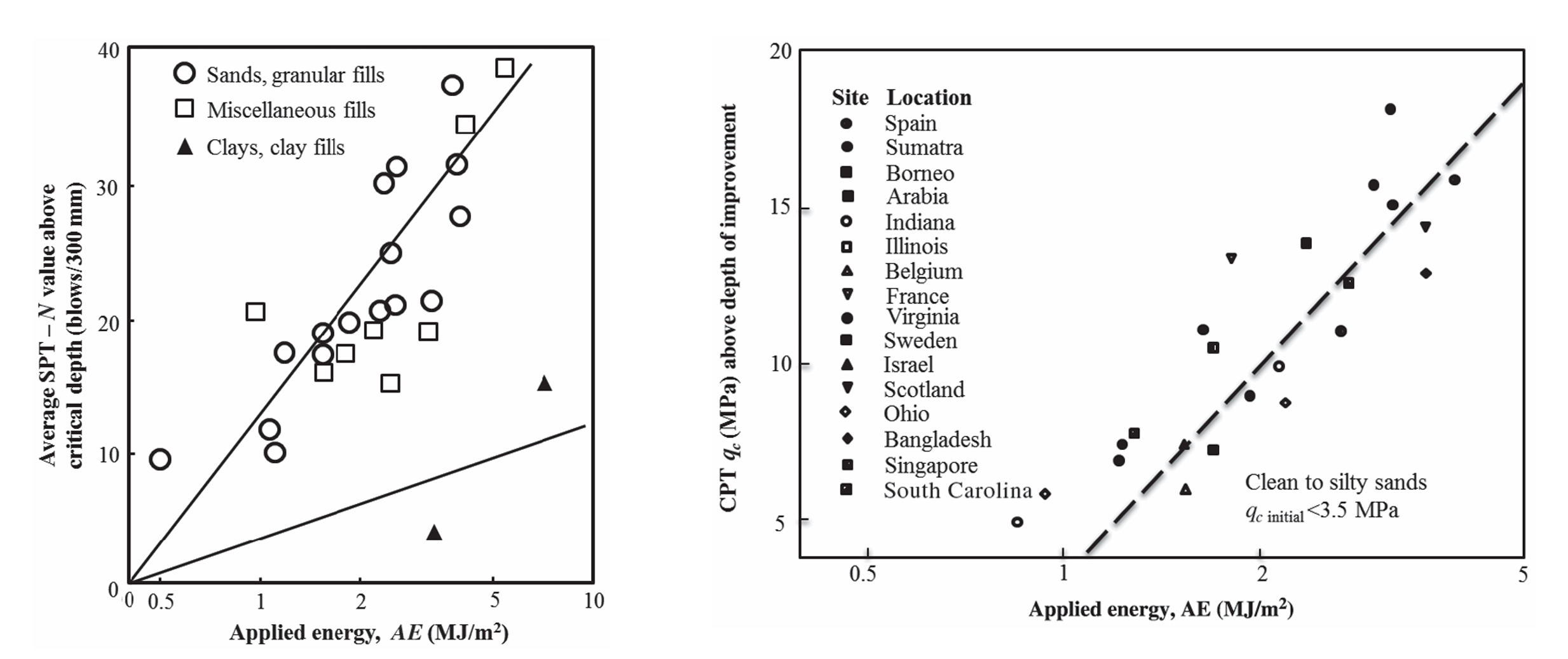
Dynamic Compaction can be modeled in Settle3 by the same familiar workflow as existing ground improvement methods. From the Ground Improvement tab, insert a new region, and select Dynamic Compaction as the method. Based on your input for the tamper properties of both high and low energy passes, Settle3 will calculate the modulus of elasticity after improvement by correlating the Applied Energy to the average SPT N or CPT qc, following the charts presented in Lukas (1995).
Once the dynamic compaction region is added, Settle3 will provide additional empirical results, including:
- Estimated depth of improvement
- Average applied energy
- Depth of impact craters
- Predicted induced settlement
- Peak particle velocity

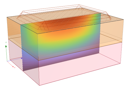
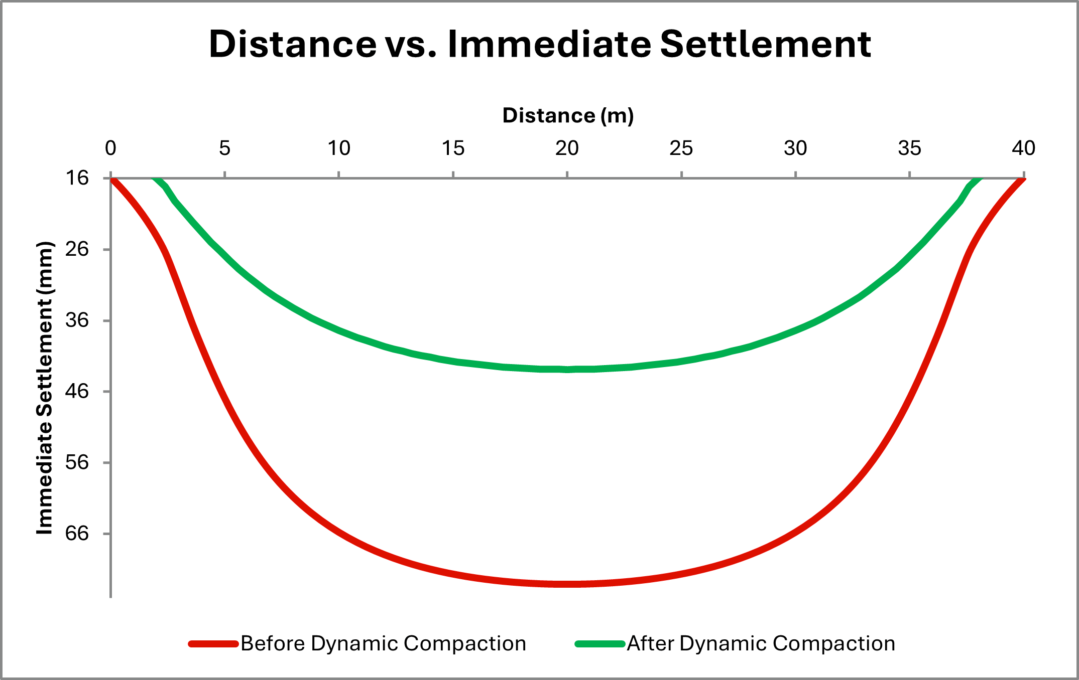
The improvement in immediate settlement along the length of the embankment is shown in Figure 4.
Whether you are designing for embankments, storage yards, or large-scale infrastructure, Settle3’s new Dynamic Compaction feature gives you the functionality to optimize your designs. Start using Settle3 today and explore the benefits of the many ground improvement methods at your fingertips.