Add Supports
1.0 Introduction
This tutorial will demonstrate how a support pattern can be added to a specific area of the model. Support patterns can be defined using two different menu options: 1) Add Support, and 2) Add Support to Surface. (Note that these options exclude geosynthetics which are added using their own options in the support menu.) This tutorial will provide step-by-step instructions for adding a support pattern using the Add Support option.
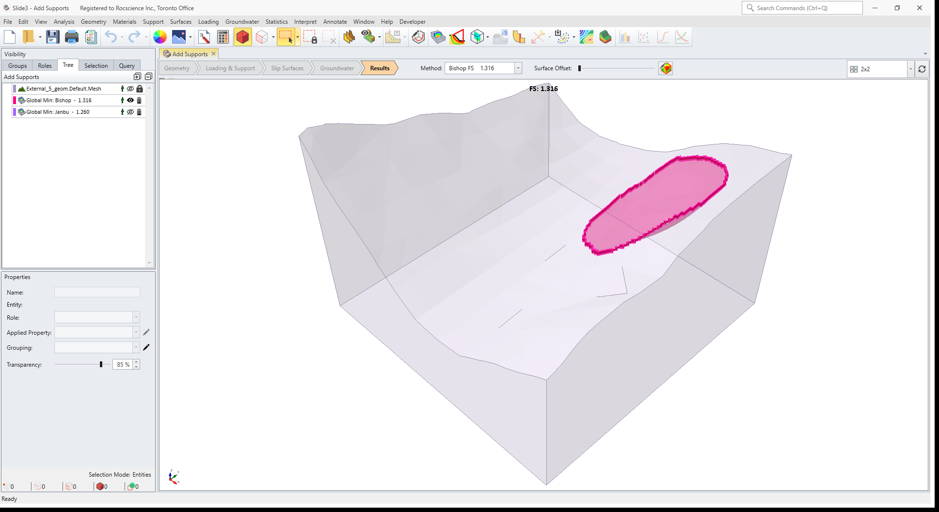
2.0 Results Without Supports
- Select File > Recent > Tutorials and read in the file Add Support – starting file from the installation folder.
- Select Analysis > Compute or select Compute
 icon in the toolbar.
 - Go to the Results tab

You should see the following results. The Bishop safety factor is about 1.3.
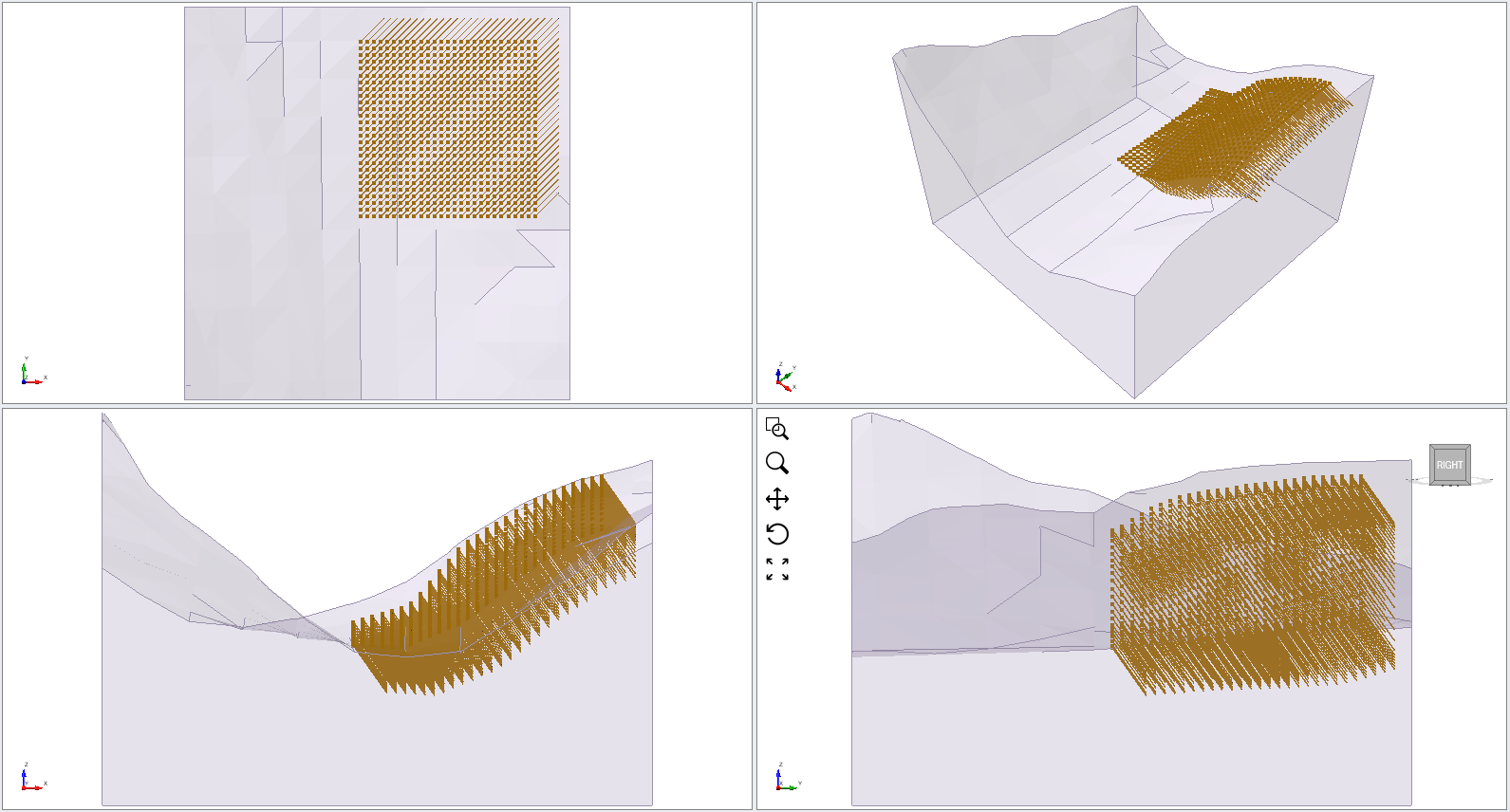
3.0 Add Supports
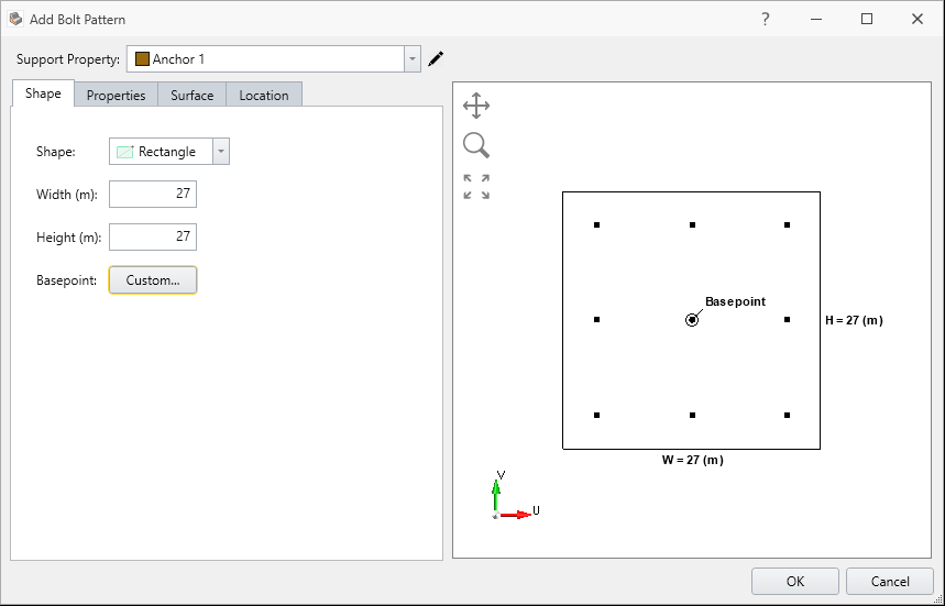
- To add supports to the model, select Supports > Add Support

- Begin by defining the Support Shape under the Shape tab in the Add Support Pattern dialog as following:
- Select Shape = Rectangle
- Enter Width (m) = 27
- Enter Height (m) = 27
- Leave the Basepoint as default.
- Bolt Length (m) = 7
- Horizontal Spacing (m) = 1
- Vertical Spacing (m) = 1
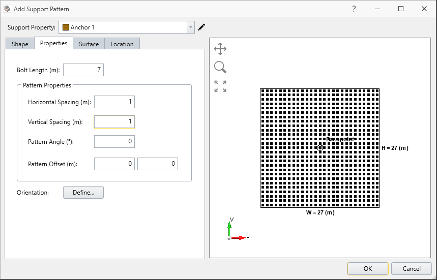
- Select Defined By = Trend/Plunge
- Trend = 45
- Plunge = 45
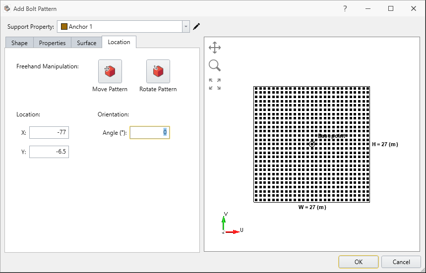
The final model with the support pattern added should now appear.
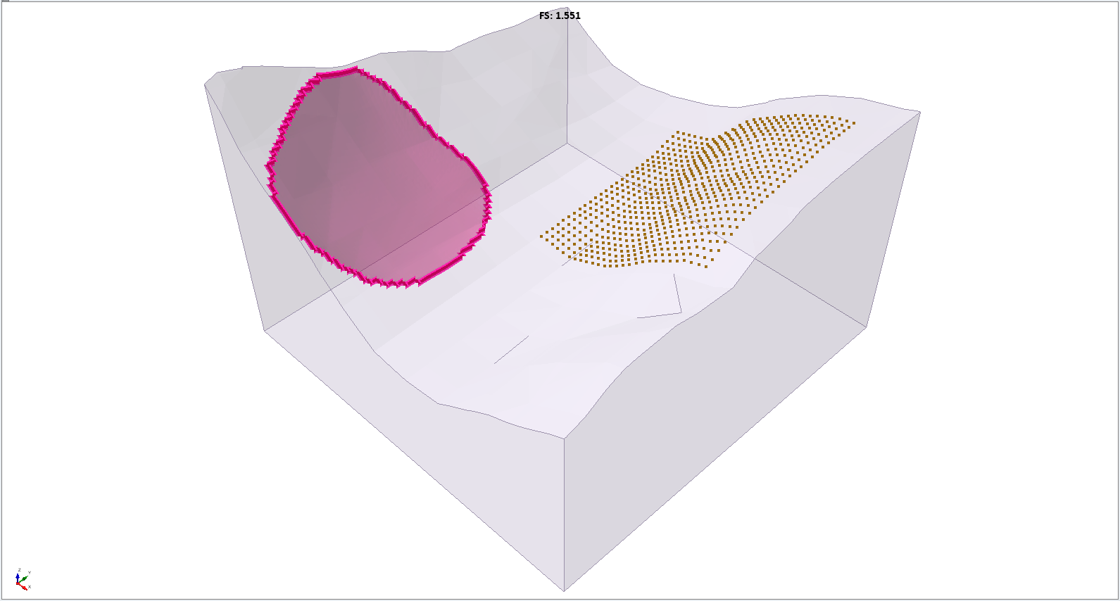
4.0 Results
- Save the file and click Compute
You should see the following results. The Bishop safety factor is about 1.5. You can see the failure surface be outside the reinforced area.
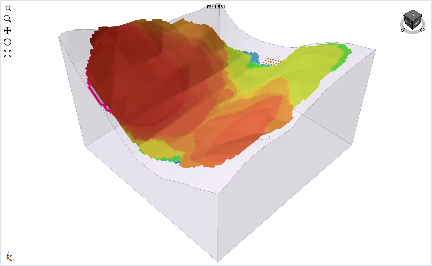
4.1 Add Surface Safety Map
- Select Interpret > Add Surface Safety Map

By selecting this feature, you can see the safety map of the computed model.
This concludes the 12 - Add Supports tutorial.