In this tutorial a steep cut is made in a sedimentary formation hosting a dike. While the sedimentary rock is highly jointed, the dike is mostly intact. The joints in the sedimentary formation are represented as a discrete fracture network (DFN) and imported into RocSlope3 in a .dxf format. There are also two large joint surfaces running parallel to the dike. Joint extents are trimmed such that the DFN only populates the sedimentary formation and not the dike.
Finished Product
The finished product of this tutorial can be found in the Tutorial 09 Trim Joints folder. All tutorial files installed with RocSlope3 can be accessed by selecting File > Recent Folders > Tutorials Folder from the RocSlope3 main menu.
2.0 Starting a Model
Open RocSlope3. You will see a blank workspace.
2.1 Project Settings
The first step to any RocSlope3 project should be to review and configure the analysis parameters for model in the Project Settings.
Select Analysis > Project Settings
or click on the Project Settings icon in the toolbar.
Select the Units tab and set Units
to Metric, stress as MPa. Units Tab in Project Settings Dialog
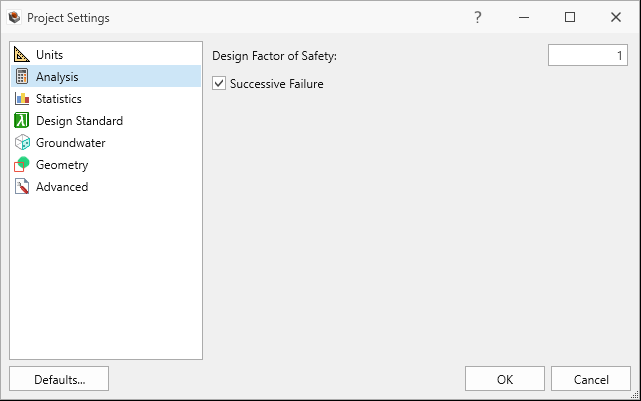
Select the Analysis tab.
Set Design Factor of Safety = 1.0
Set Successive Failure = ON.
Set Combined blocks = OFF. We will only be looking at unit blocks in this tutorial.
Analysis Tab in Project Settings Dialog
Click OK to save the Project Settings and to close the dialog.
These project settings are configured to run a deterministic block stability analysis considering successive block failure.
3.0 Defining Material Properties
Define the Material Properties
Select Materials > Define Materials. By default, three Material Properties (Material 1, Material 2, and Material 3) are defined in the Define Materials dialog.
Select Material 1.
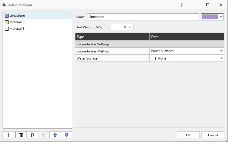
Enter Name = Limestone.
Set Unit Weight = 0.026 MN/m3.
No Water Surface applied.
Limestone Material Property in Define Materials Dialog
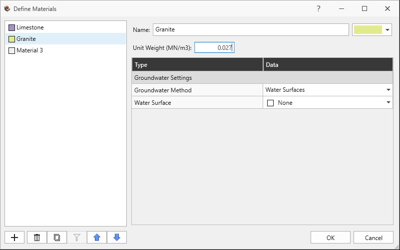
Select Material 2.
Enter Name = Granite.
Set Unit Weight = 0.027 MN/m3.
No Water Surface applied.
Granite Material Property in Define Materials Dialog
Select Material 3
Click the Delete button on the bottom-left of the dialog to delete Material 3.
Click OK to save the material properties and exit the dialog.
4.0 Creating Geometry
The Slope Wizard tool can be used to quickly create a simple extruded slope containing multiple material strata. In this tutorial, the Slope Wizard mainly serves to create the slope cut geometry of the sedimentary formation. The dike will be created in the following section using other geometry tools available in RocSlope3.
4.1 Slope Creation via Slope Wizard
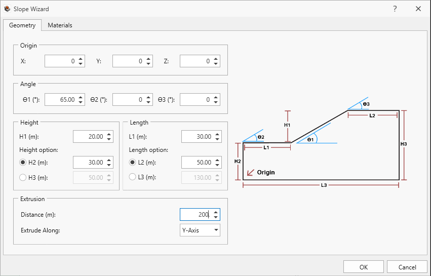
The slope has a dip of 65 degrees and a height of 20 m. The domain of interest runs 200 m into the page (extrusion length).
Select Geometry > Slope Wizard
In the Slope Wizard dialog, enter the following inputs in the Geometry tab.
Set Origin X = 0
Set Origin Y = 0
Set Origin Z = 0
Set Angle θ1 = 65 degrees
Set Angle θ2 = 0 degrees
Set Angle θ3 = 0 degrees
Set Height H1 = 20 m
Set Height H2 = 30 m
Set Length L1 = 30 m
Set Length L2 = 50 m
Set Extrusion Distance = 200 m
Set Extrude Along = Y-Axis.
Slope Wizard Dialog
Click on the Materials tab. You should find options to create multiple material strata. For this tutorial, leave the fields in the Material tab at their default, so that the simple extruded slope contains only Material 1 (Limestone).
Click OK.
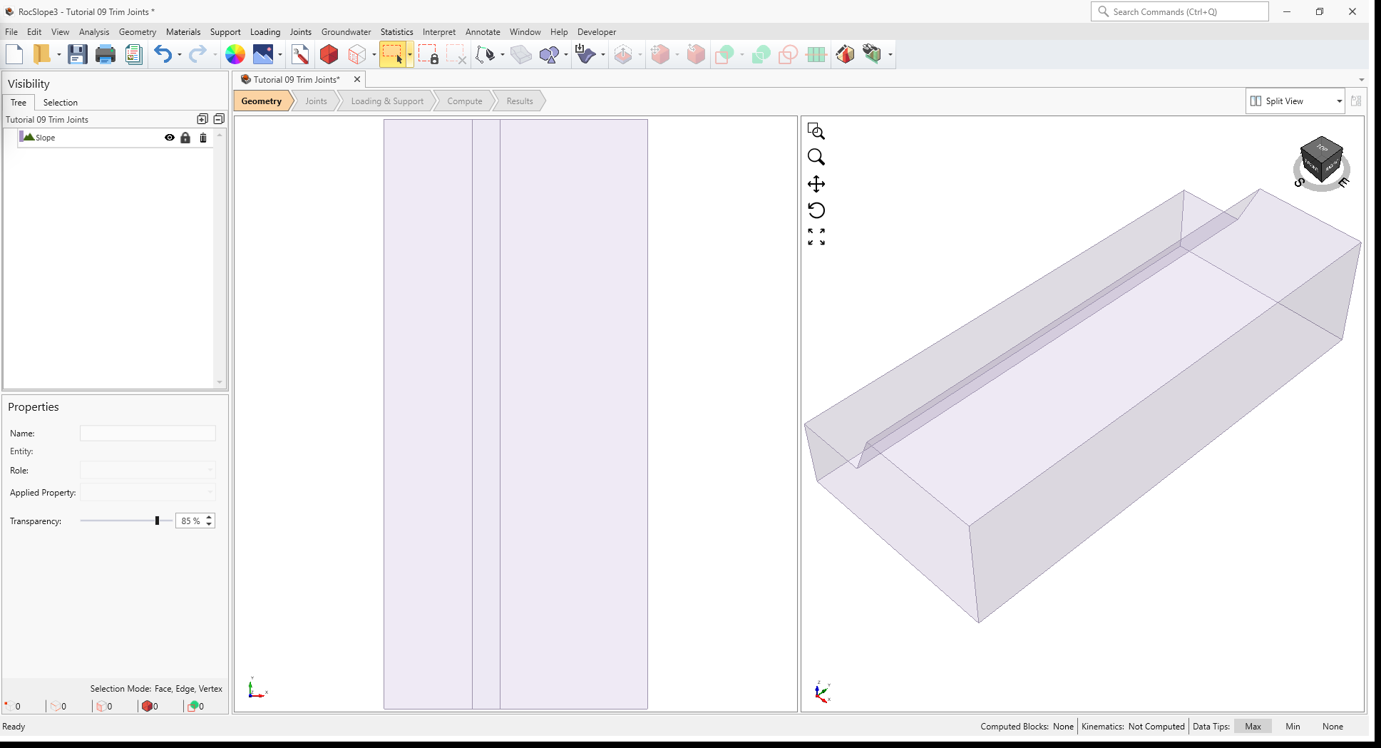
A simple extruded slope geometry has been created and assigned material of Limestone.
3D View of Slope external geometry created from Slope Wizard
4.2 Dike Creation via Geometry Tools
The dike consists of a granite, which is a different material from the sedimentary formation (Limestone) and needs to be created as its own material volume. We will construct 2 planar surfaces depicting the dike material boundaries. These planes also serve to divide the sedimentary rock and dike into separate material volumes.
4.2.1 Plane Creation
Create planar surfaces that represent the interfaces between the dike and sedimentary formation.
Geometry > 3D Primitive Geometry > Plane
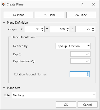
Expand the Plane Definition section and define the plane as follows:
Plane Definition
Origin (X,Y,Z) = 35,100,25
Plane Orientation
Defined by = Dip/Dip Direction
Dip = 70 degrees
Dip Direction = 70 degrees
Rotation Around Normal = 0
Role = Geology
Create Plane Dialog
Click OK to finish defining the plane and to exit the dialog.
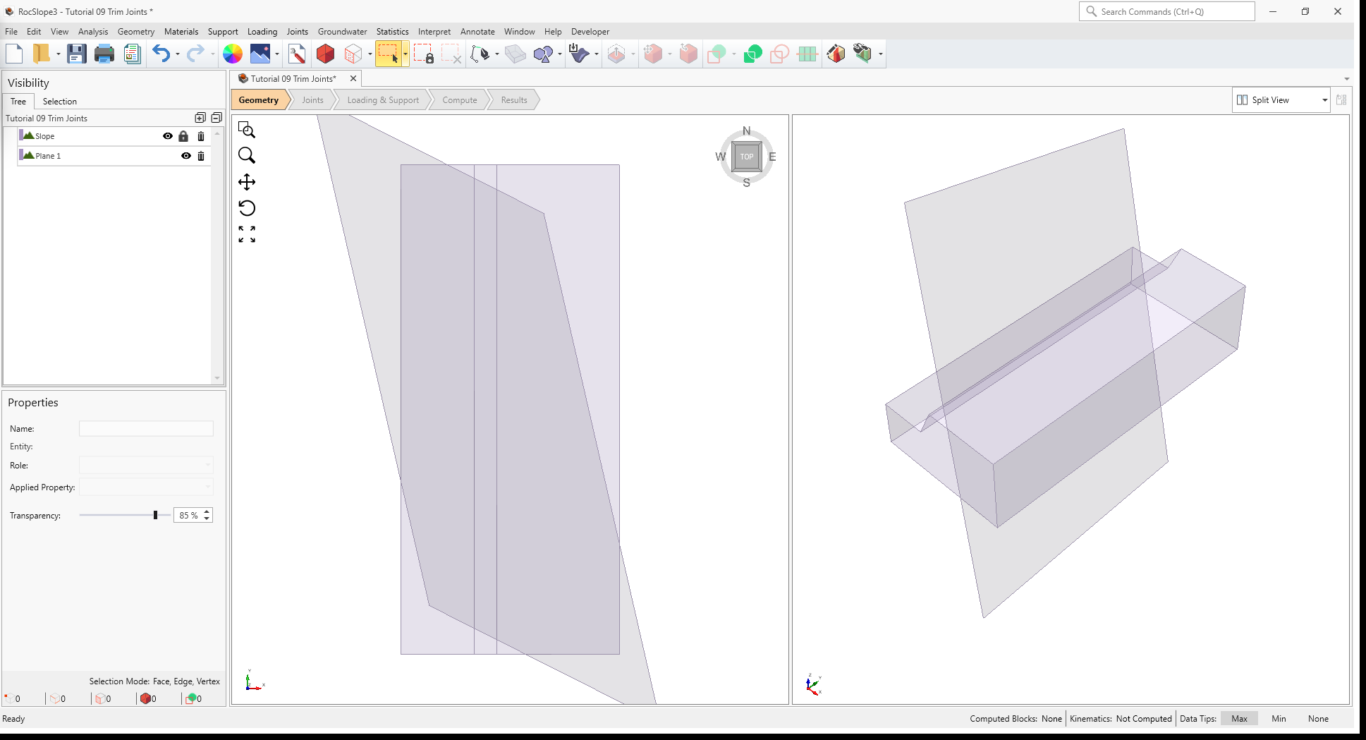
A plane is created.
3D View of Slope and Plane 1
Create a second plane by making a copy of the first plane and offsetting it by a distance.
In the Visibility Tree, select Plane 1. This plane should now be highlighted in the 3D views.
Geometry > Copy > Copy (Array)
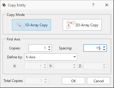
In the Copy Entity dialog:
Copy Mode = 1D-Array Copy
Copies = 1
Spacing = 15
Define by = X-Axis
Inputs for plane copy and offset
Click OK.
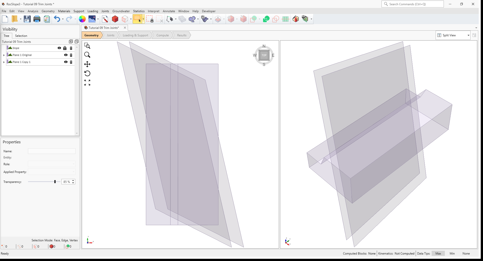
The second plane is created and offset from the first plane by 15m in the x-axis direction.
3D View of Slope, Plane 1 Original, and Plane 1 Copy 1
4.2.2 Divide Material Volumes
In the Visibility Tree, notice that the Slope volume entity has a lock symbol beside its entry, meaning that it is an “External”. To divide the “External” volume by the planes just created:
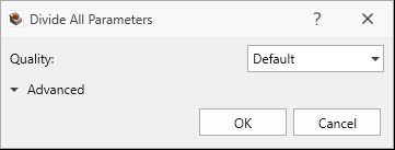
Geometry > 3D Boolean > Divide All Geometry
Use default
parameters in the Divide All Parameters dialog.
Click OK.
After Divide All, there should be 3 slope volume entities, and each is an “External”.
3D View of Slope_1, Slope_2, and Slope_3 external pieces after Divide All
4.3 Material Properties
All volumes have the first material property (Limestone) assigned by default. This material property is appropriate for the sedimentary formation but not the dike.
To change the material property of the dike volume:
Select the dike volume entity (Slope_2) from the Visibility Tree.
In the Properties pane at the bottom left, change the Applied Property to Granite.
The slope model should now appear with Slope_1 and Slope_3 assigned with Limestone material and Slope_2 assigned with Granite material.
3D View showing slope geometry with dike
5.0 Add Joints from Surface Geometries
The sedimentary formation is to be populated with a DFN, imported from DFN clean.dxf file (this is included in the RocSlope3 Tutorials folder). We will also create two joint surfaces parallel to the dike.
5.1 Import DFN
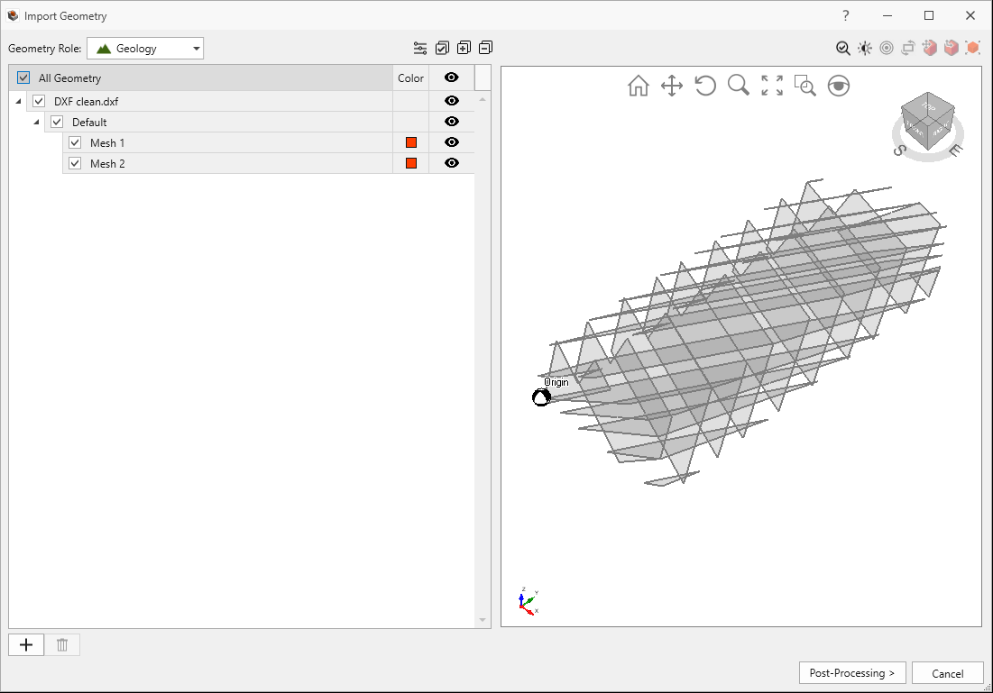
Select Geometry > Import/Export > Import Geometry
Select and open DFN clean.dxf.
In the Import Geometry dialog, you should see two parallel joint sets. Select “All Geometry” for import.
Click Post-Processing.
Click Done.
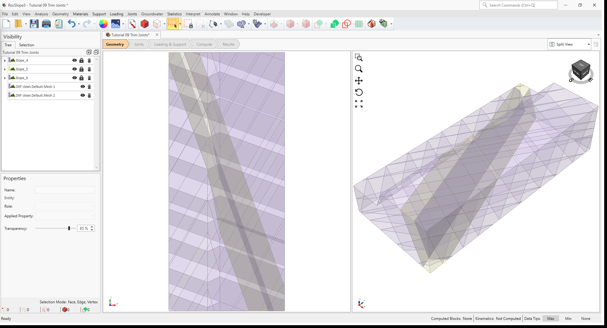
In the Visibility Tree, two new surface entities should have appeared, one for each parallel joint set.
3D View showing the slope and imported surfaces
Typically, geometry simplification and repair are recommended following geometry import or modification. However, the .dxf has already been cleaned and repaired, so these steps can be skipped for this tutorial.
5.2 Create Joint Planes
Similar to how we created the dike boundaries, we will create the joint planes by first constructing a single plane, then copying and offsetting for the second plane.
Select Geometry > 3D Primitive Geometry > Plane.
Origin (X,Y,Z) = 28,102,30
Dip = 70 degrees
Dip Direction = 70 degrees
Rotation Around Normal = 0
Role = Geology
In the Visibility Tree, select Plane 4. This plane should now be highlighted in the 3D views.
Geometry > Copy > Copy (Array)
In the Copy Entity dialog:
Copy Mode = 1D-Array Copy
Copies = 1
Spacing = 25
Define by = X-Axis
Click OK.
5.3 Define Joint Properties
The DFN and the two other joint surfaces are still geometry surfaces at this point without shear strength properties.
To define joint shear strengths:
Select Joints > Define Joint Properties
Add 2 new joint properties (for 3 in total) by clicking the add icon.
For Joint Property 1:
Set Strength Type = Mohr-Coulomb
Set Cohesion 0 MPa.
Set Phi = 30 deg.
Set Override by Material = FALSE.
Set Waviness = 0.
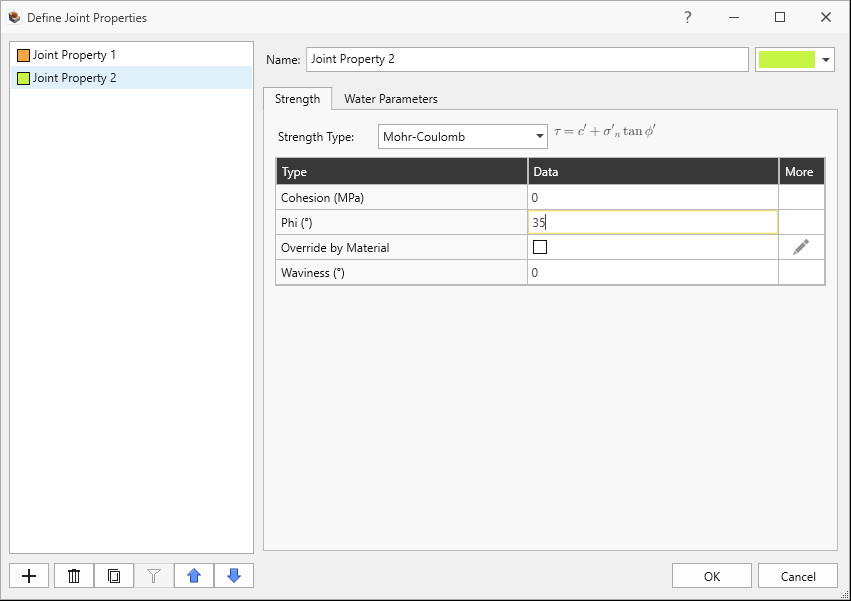
For Joint Property 2:
Set Strength Type = Mohr-Coulomb
Set Cohesion 0 MPa.
Set Phi = 35 deg.
Set Override by Material = FALSE.
Set Waviness = 0.
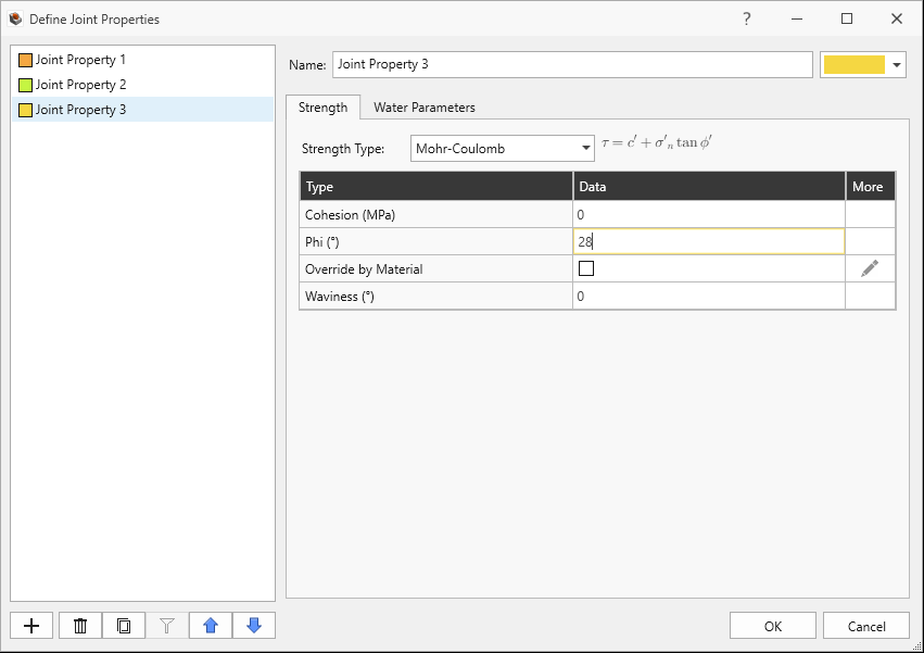
For Joint Property 3:
Set Strength Type = Mohr-Coulomb
Set Cohesion 0 MPa.
Set Phi = 28 deg.
Set Override by Material = FALSE.
Set Waviness = 0.
Click OK to save the joint properties and to exit the dialog.
Joint Properties 1 and 2 are to be applied to the DFN, whereas Joint Property 3 is to be applied to the other two joints.
5.4 Add Joint Surfaces
In the Visibility Tree, select the DFN surface entity with joint dip/dip directions 40 deg/300 deg (DXF clean.Default.Mesh 1).
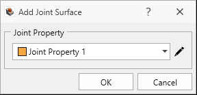
Select Joints > Add Joint Surface.
In the Add Joint Surface dialog, set Joint Property = Joint Property 1. Add Joint Surface Dialog with Joint Property 1 Selected
Click OK.
To assign another surface entity as a joint surface:
In the Visibility Tree, select the DFN surface entity with joint dip/dip direction 70 deg/200 deg (DXF clean.Default.Mesh 2).
Select Joints > Add Joint Surface .
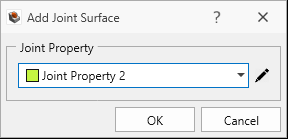
In the Add Joint Surface dialog, set Joint Property = Joint Property 2. Add Joint Surface Dialog with Joint Property 2 Selected
Click OK.
To assign the last two surfaces as Joint Surfaces:
In the Visibility Tree, select Plane 4 Original, hold down the CTRL key and select Plane 4 Copy 1..
Select Joints > Add Joint Surface .
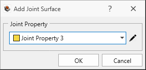
In the Add Joint Surface dialog, set Joint Property = Joint Property 3. Add Joint Surface Dialog with Joint Property 3 Selected
Click OK.
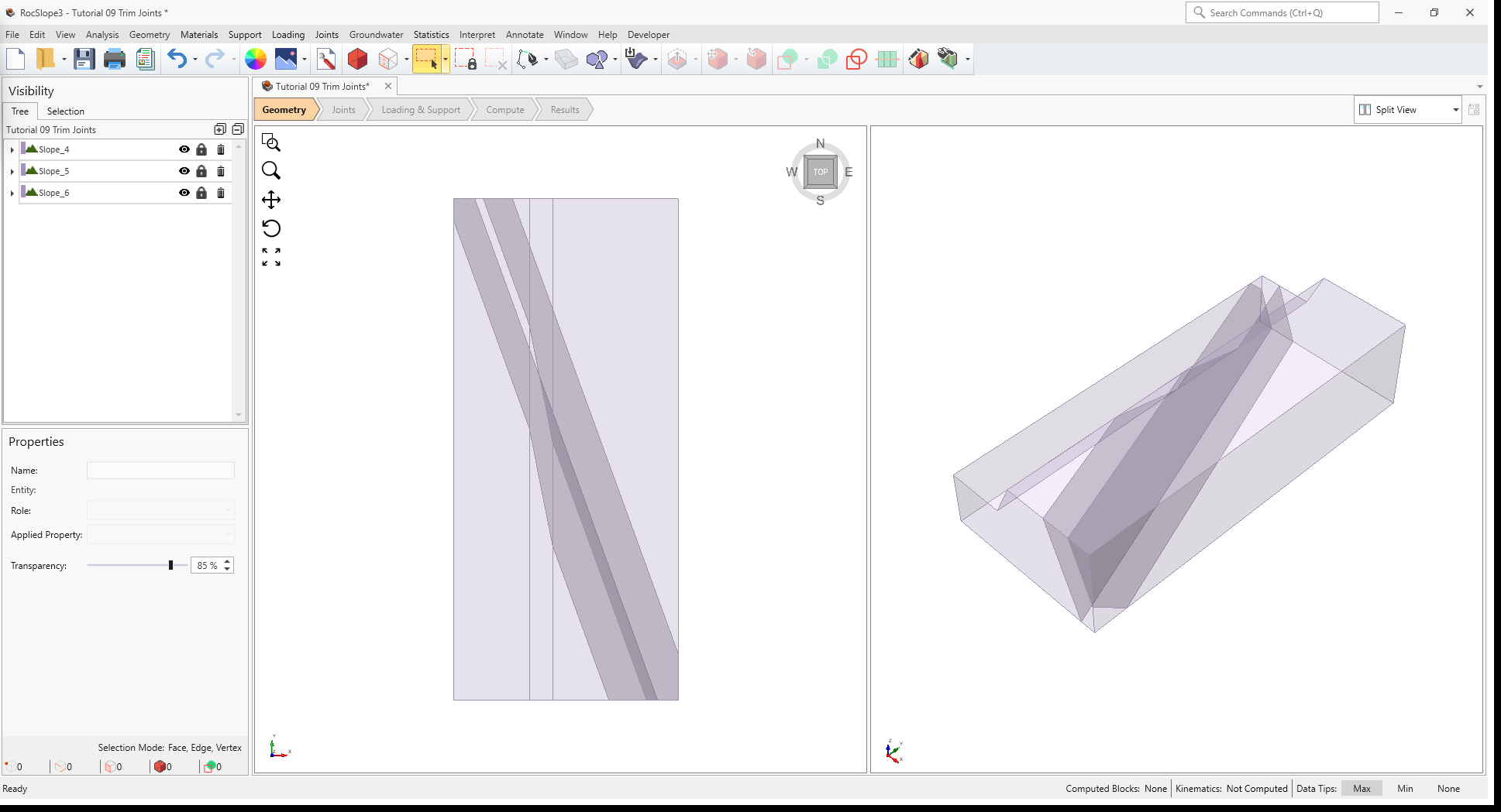
All joint surfaces have been added to the model with appropriate joint properties.
3D View with slope and joints trimmed to the limestone volume boundaries (no DFN in dike)
5.5 Trim Joints
Trim the joints to restrict the DFN extent to the sedimentary formation (Limestone):
Joints > Trim Joints
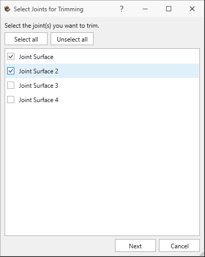
In the Select Joints for Trimming dialog, select the joint surfaces that represent the DFN (Joint Surface and Joint Surface 2).Select joints for trimming dialog
Click Next.
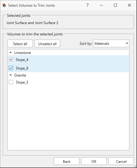
In the Select Volumes to Trim Joints dialog, select the volumes with “Limestone” as the assigned material (Slope_1 and Slope_3). The joints will be trimmed to the boundaries of these volumes.Trim joints to the boundaries of the Limestone volumes
Click OK
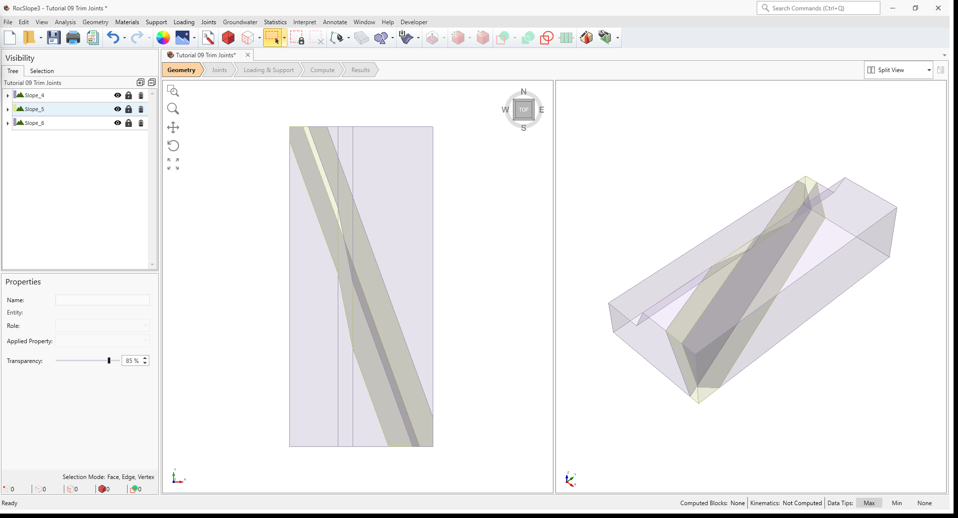
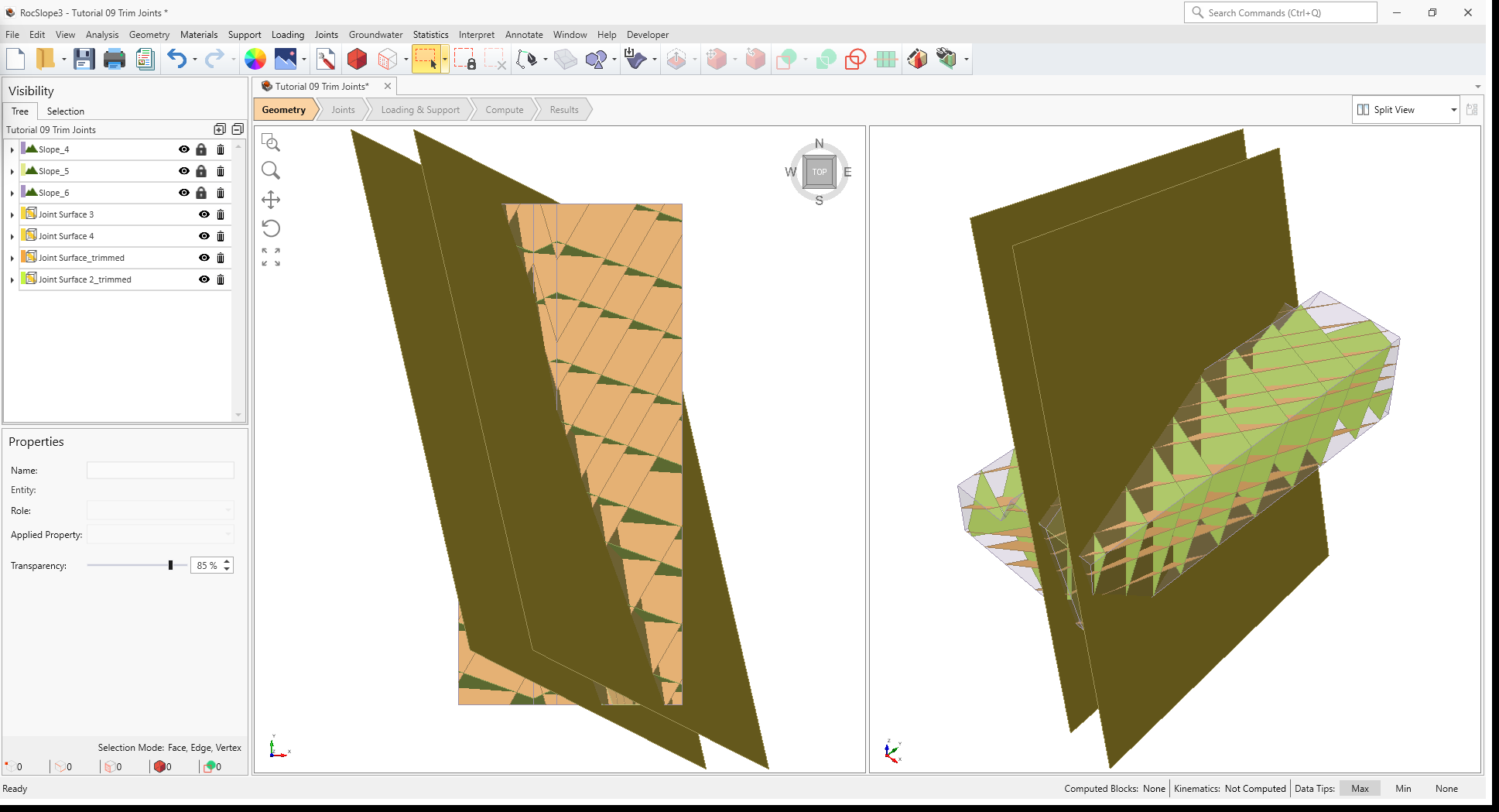
The slope model should now appear as follows with the selected DFN surfaces cropped to the selected volumes.
3D View with slope and joints trimmed to the limestone volume boundaries (no DFN in dike)
6.0 Compute
The model is now ready to compute.
Select the Compute workflow tab
In the toolbar, click Compute Blocks (or select Analysis > Compute Blocks in the menu).3D View showing All Valid Unit Blocks results after Compute Blocks
Click Compute Kinematics (or select Analysis > Compute Kinematics in the menu).
7.0 Results
Select the Results workflow tab
Select Interpret > Contour Blocksto view the Factor of Safety of the blocks.
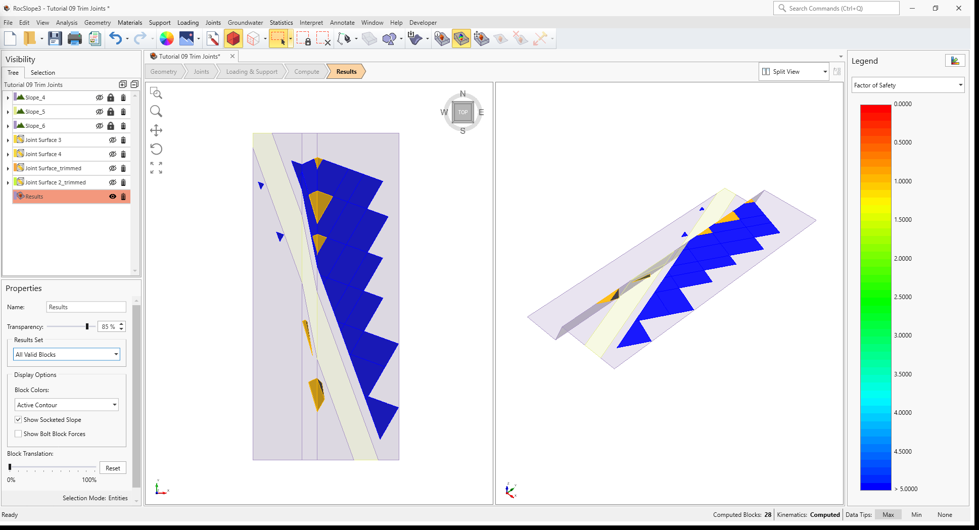
In the Visibility Tree, select the Results
node, and ensure the Block Type = Unit Blocks and Results Set = All Valid Unit Blocks. This means that you are viewing all valid unit blocks that formed as a result of joint intersections.
3D View of unit block results contoured by Factor of Safety
Notice that blocks only formed in the sedimentary layers.
 icon in the toolbar.
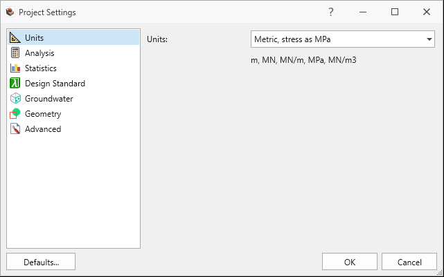
 button on the bottom-left of the dialog to delete Material 3.


 icon.
icon. 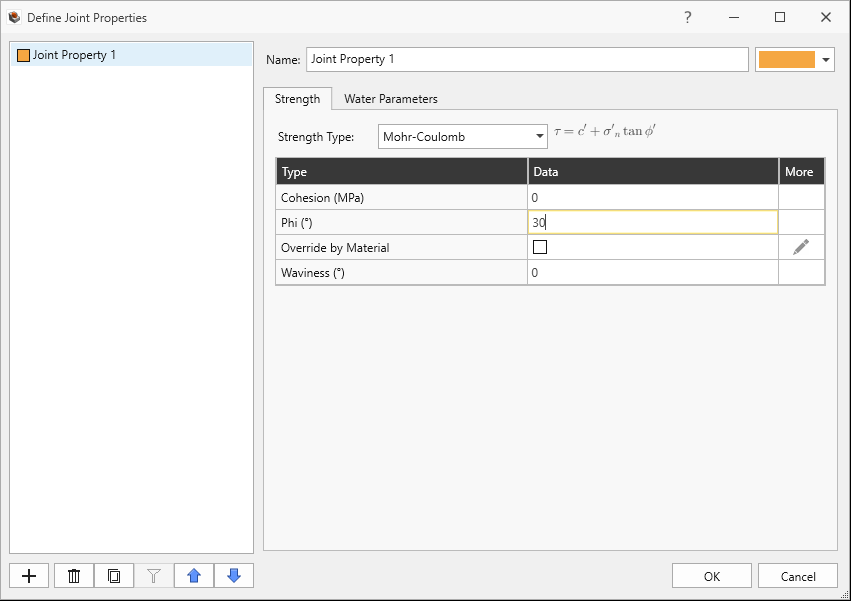
 .
. 


 (or select Analysis > Compute Blocks in the menu).
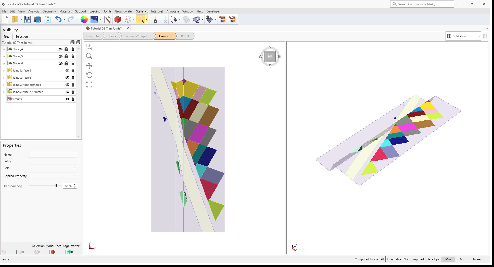
 (or select Analysis > Compute Kinematics in the menu).
 to view the Factor of Safety of the blocks.