5 - Successive Failure
1.0 Introduction
Successive failure of a rock slope refers to a phenomenon where multiple failures occur in a rock slope in quick succession, leading to a large-scale slope failure. This type of failure can occur when initial failures trigger additional failures as blocks are further destabilized. This analysis is important for many reasons including:
- Identifying key blocks. A key block is a block whose removal is required for the subsequent destabilization of larger masses of blocks. If key blocks are stabilized, then the slope is stabilized.
- Identifying the total failure depth behind key blocks. Bolt supports must have adequate length to anchor blocks into competent rock mass.
- Identifying extent of failure volumes due to successive failure of the slope.
This tutorial covers how to utilize the Successive Failure analysis options in RocSlope3, and view the failure iteration and failure depth of blocks.
Finished Product
The finished product of this tutorial can be found in the Tutorial 05 Successive Failure folder. All tutorial files installed with RocSlope3 can be accessed by selecting File > Recent Folders > Tutorials Folder from the RocSlope3 main menu.
2.0 Opening the Starting File
- Select File > Recent > Tutorials Folder.
- Go to the Tutorial 05 Successive Failure folder and open
the file Tutorial 05 Successive Failure.rocslope_model.
This model already has the following defined and provides a good starting point to start computing blocks:
- Project Settings
- Material Properties
- External Geometry
- Joint Properties
- Measured Joints
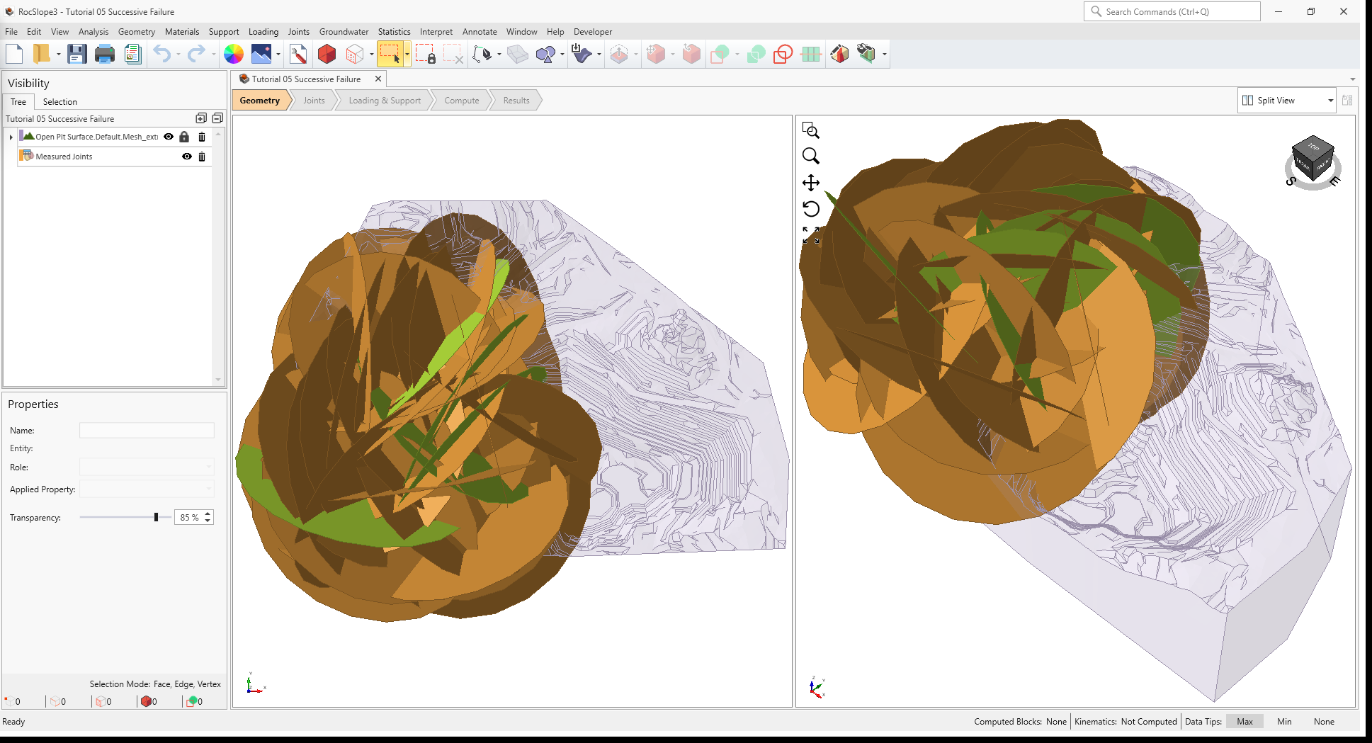
In the starting model, Measured Joints are defined over the west extents of open pit. The size of
the joints are relatively large (Radius = 500 m) so unit blocks have the potential of forming deep behind the free
surface of the slope, some completely behind daylighting blocks.
2.1 Project Settings
Review the Project Settings.
- Select Analysis > Project Settings

- Select the Units tab. Ensure Units are Metric, stress as
MPa.
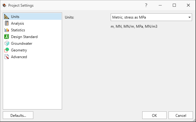
Units tab in Project Settings dialog - Select the Analysis tab.
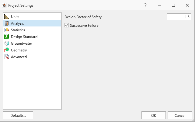
Analysis tab in Project Settings dialog - Ensure Design Factor of Safety = 1.5.
- Ensure Successive Failure is ON. We will be analyzing successive failures by iterating through each stage of failed blocks until no more blocks can be removed.
- Ensure Combined blocks is OFF
- Click Cancel to exit the dialog.
2.2 Material Properties
Review the Material Properties.
- Select Materials > Define Materials

- One (1) material property is defined in the Define Materials dialog. The Schist
material property has:
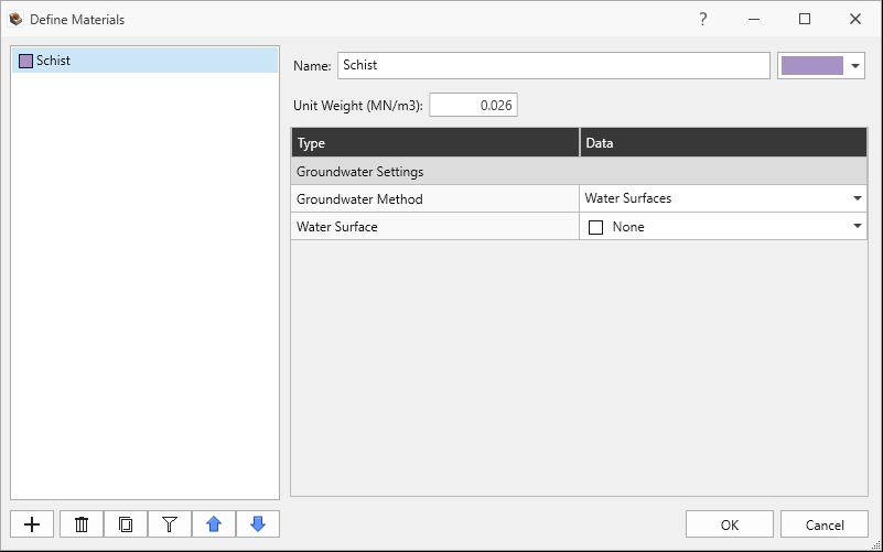
Schist Material Property in Define Materials dialog - Unit Weight = 0.026 MN/m3.
- No Water Surface applied.
- Click Cancel to exit the dialog.
2.3 External Geometry
The External is of a pit shell and composed of one volume assigned with the Schist material property.
2.4 Joint Properties
Review the Joint Properties.
- Select Joints > Define Joint Properties
 . Two (2) joint properties are defined.
 - The Smooth joint property has:
- Strength Type = Mohr-Coulomb
- Cohesion = 0 MPa
- Phi = 10 degrees
- Waviness = 0 degrees
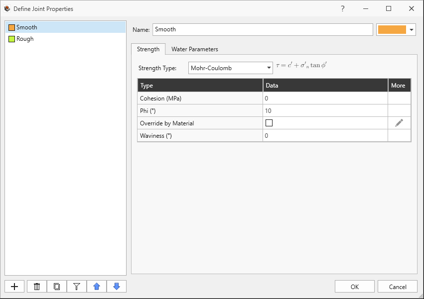
Smooth Joint Property Strength tab in Define Joint Properties dialog - Water Pressure Method = Dry
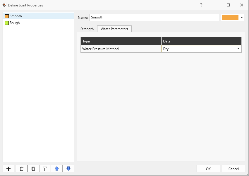
Smooth Joint Property Water Parameters tab in Define Joint Properties dialog
- Strength Type = Mohr-Coulomb
- Cohesion = 0 MPa
- Phi = 30 degrees
- Waviness = 0 degrees.
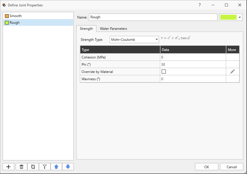
Rough Joint Property Strength tab in Define Joint Properties dialog - Water Pressure Method = Dry
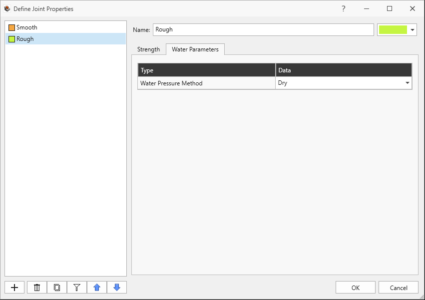
Rough Joint Property Water Parameters tab in Define Joint Properties dialog
2.5 Measured Joints
Review the Measured Joints.
Select Joints > Define Measured Joints
 . 40 Measured Joints are defined.
Listed in order of Dip, Dip Direction, X, Y, Z, Radius, and Joint Property:
Dip Dip Direction X Y Z Radius Joint Property 59 48 -390 -115 1018 500 Rough 77 131 -319 -337 1004 500 Rough 78 123 -313 -157 1003 500 Rough 78 313 -486 128 1037 500 Rough 61 13 -793 -447 1099 500 Rough 89 255 -272 -65 994 500 Smooth 51 341 -375 -594 1015 500 Smooth 67 107 -548 47 1050 500 Smooth 57 86 -281 91 996 500 Smooth 82 105 -758 33 1092 500 Smooth 53 62 -546 -100 1049 500 Smooth 46 84 -665 -224 1073 500 Smooth 55 79 -772 -386 1094 500 Smooth 29 223 -798 -400 1100 500 Smooth 50 82 -305 193 1001 500 Smooth 34 33 -699 -504 1080 500 Smooth 39 57 -348 -272 1010 500 Smooth 81 36 -258 -51 992 500 Smooth 58 314 -544 -193 1049 500 Smooth 39 211 -744 -599 1089 500 Smooth 81 268 -797 108 1099 500 Smooth 65 336 -455 104 1031 500 Smooth 78 317 -575 -54 1055 500 Smooth 62 133 -656 -479 1071 500 Smooth 27 283 -769 -258 1094 500 Smooth 30 167 -458 -465 1032 500 Smooth 33 132 -253 -539 991 500 Smooth 60 336 -580 80 1056 500 Smooth 30 39 -583 168 1057 500 Smooth 28 76 -362 -30 1012 500 Smooth 17 101 -362 -432 1012 500 Smooth 10 249 -511 -162 1042 500 Smooth 19 343 -631 112 1066 500 Smooth 45 58 -789 -329 1098 500 Smooth 26 213 -628 60 1066 500 Smooth 84 351 -516 -421 1043 500 Smooth 51 162 -339 -320 1008 500 Smooth 49 178 -253 -309 991 500 Smooth 77 291 -403 114 1021 500 Smooth 54 51 -417 -421 1023 500 Smooth 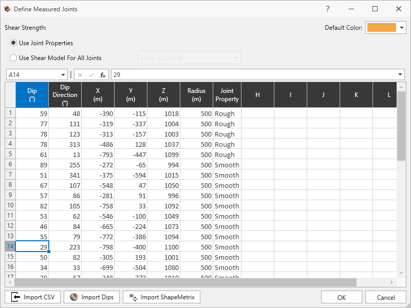
40 Joints in Define Measured Joints dialog - Click Cancel to exit the dialog.
3.0 Compute
RocSlope3 has a two-part compute process.
3.1 Compute Blocks
The first step is to compute the unit blocks which may potentially be formed by the intersection of joints with other joints and the intersection of joints with the free surface.
To compute the unit blocks:
- Navigate to the Compute workflow tab

- Select Analysis > Compute Blocks

As compute is run, the progress bar reports the compute status. Once compute is finished, the Results node is added to the Visibility Tree and All Valid Unit Blocks are blocks are shown in the viewport. The Results node consists of the collection of valid unit blocks and the socketed slope. The original External and Measured Joints visibility is turned off.
Once compute is finished, the unit blocks are coloured according to the Block Color option (Random
Colors) set in the Results node's Property pane.
Compute Blocks only determines the geometry of the unit blocks. In order to obtain other information such as the factor of safety, Compute Kinematics needs to be run.
3.2 Compute Kinematics
The second and final compute step is to compute the removability, forces, and factor of safety for each of the valid unit blocks.
To compute the block kinematics:
- Ensure that the Compute workflow tab is the active workflow.
- Select Analysis > Compute Kinematics

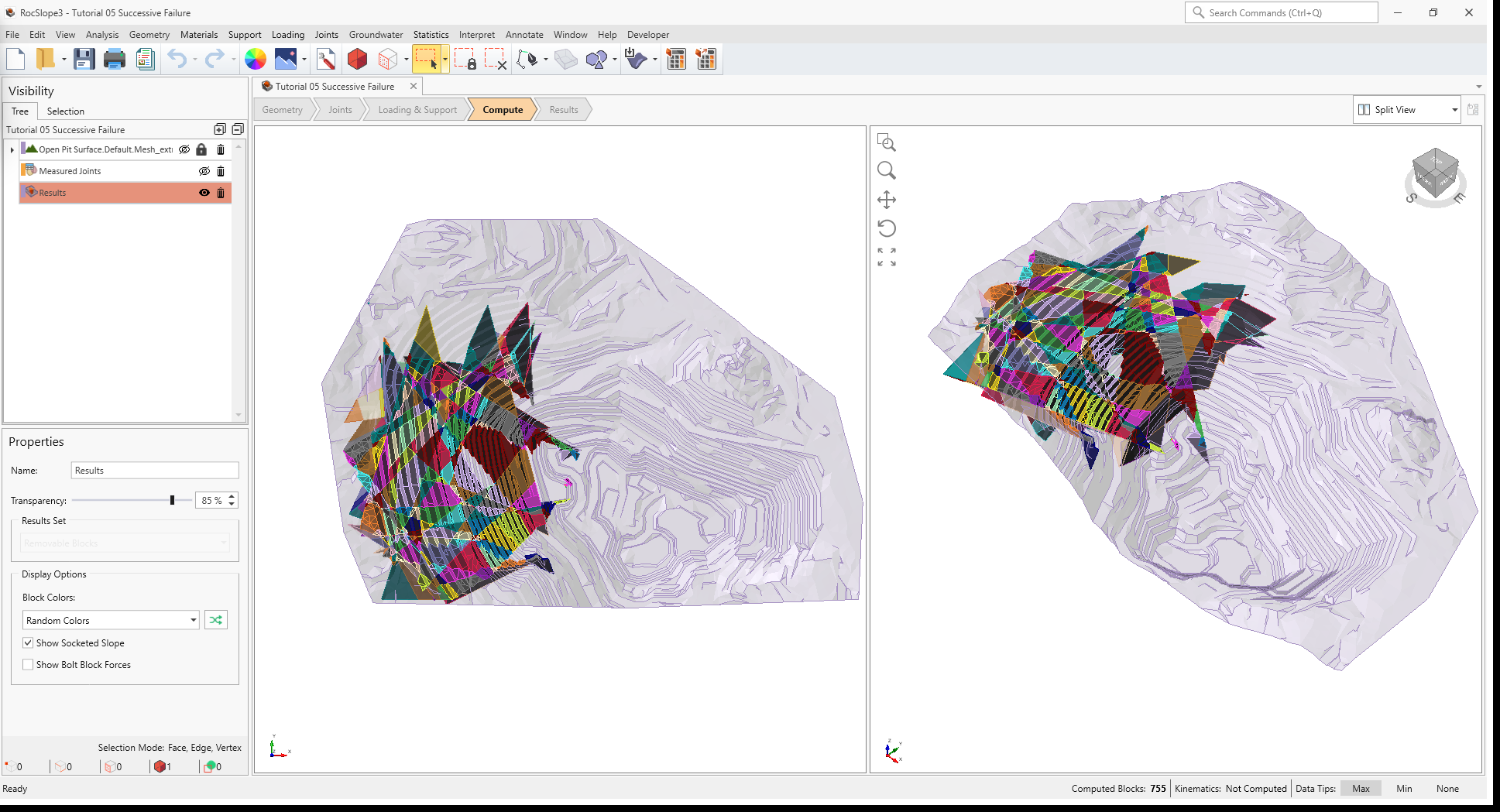
As compute is run, the progress bar reports the compute status. By default, after Compute Kinematics
is run, only Removable Unit Blocks are shown.
In a Successive Failure mode of analysis, several Failure Iterations may be performed. In the first Failure Iteration, only immediately removable daylighting blocks are analyzed. Any unit blocks which have a factor of safety less than the Design Factor of Safety (set in Project Settings) is considered "failed". These unit blocks are also known as "key blocks". The stability of key blocks control the global stability of the slope. As key blocks fail and are detached from the slope, potential constraints in joint faces (in regards to removability and valid sliding direction) are removed and become free faces which no longer support the block or provide shear resistance to sliding. As such, the failure proceeds in a successive manner. See the Analysis topic for more information on Successive Failure.
4.0 Interpreting Results
Once both blocks and kinematics are computed, all block results can be viewed in a table format.
4.1 Block Information
To view all block results:
- Navigate to the Results workflow tab

- Select Interpret > Block Information

Visualizing blocks can be difficult when the slope extents are large compared to the block extents.
To zoom into all blocks:
- Select Interpret > Zoom To All Blocks

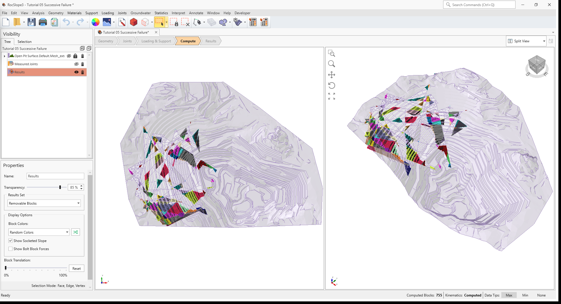
The Block Information pane shows the collection of blocks according to the Block Type and Results Set settings. The Block Type and Results Set shown can be selected in the Results tab of the Display Options, or the Properties pane for the Results Node. By default, only Removable Unit Blocks are coloured. In the case of Successive Failure, it may be more beneficial to only colour the failed unit blocks. Failed unit blocks are blocks which have a factor of safety less than the Design Factor of Safety.
To colour Failed Unit Blocks Only:
- Select View > Display Options

- Navigate to the Results tab in the Display Options dialog.
- Set Block Type = Unit Blocks and Results Set = Failed Unit Blocks (FS < Design FS)
- Click OK to close the dialog.
OR
- Select the Results node from the Visibility Tree.
- In the Results node Properties pane, set Block Type = Unit Type and Results Set = Failed Unit Blocks (FS < Design FS).
Failed Unit Blocks Only are now coloured according to Random Colors.
Note that the Failure Iteration column is visible for a Successive Failure analysis. The Failure Iteration indicates the step in which the unit block fails. It is not a true representation of the complex unraveling mechanism, but rather for notation and filtering.
4.2 Edit Filters
To see the progressive unravelling of the slope, we can toggle the Failure Iteration quick filter under the Filter Options > Edit Filters section.
- At the top of the Block Information pane, click Filter Options

- Expand the Edit Filters section.
- For the Failure Iteration quick filter, increase the minimum value from 1 to
2 and hit ENTER. All unit blocks which are immediately removable and have failed (i.e., key blocks) are filtered
out and hidden in the viewport.
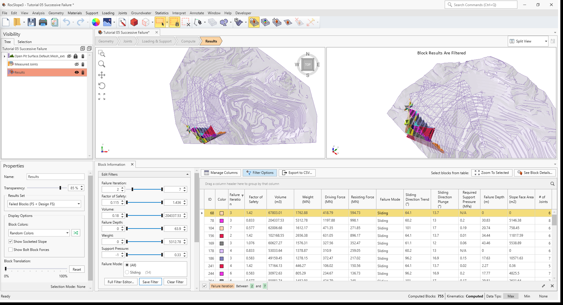
3D View and Block Information pane showing Failed Unit Blocks with key blocks filtered out - Step 2 can be repeated to show the successive failure of the slope.
- Select the Clear Filter button to remove the filter.
Alternatively:
- Hover the mouse over the Failure Iteration header in the Block Information listing and click the small filter
symbol
 that appears.
 - In the Filter Rules tab, set the operator to Is greater than and the value to 1; OR
- In the Filter Values tab, select all checkboxes except leave 1 unchecked. The key blocks are hidden.
- Select the Clear Filter button in the pop-out dialog to remove the filter.
4.3 Contour Blocks
In RocSlope3, blocks can be contoured by several metrics. In a Successive Failure analysis, the Failure Iteration and Failure Depth are especially relevant.
To show block contours:
- Ensure Block Type = Unit Blocks and Results Set = Failed Unit Blocks (FS < Design FS) in the Results node Properties pane.
- Select Interpret > Contour Blocks

- From the Contour pane on the right of the screen, select Failure Iteration.
Blocks are coloured by the failure iteration that it belongs to. This is also an easy way to quickly identify
key blocks and visually see the effects of block failures on adjacent unit blocks.
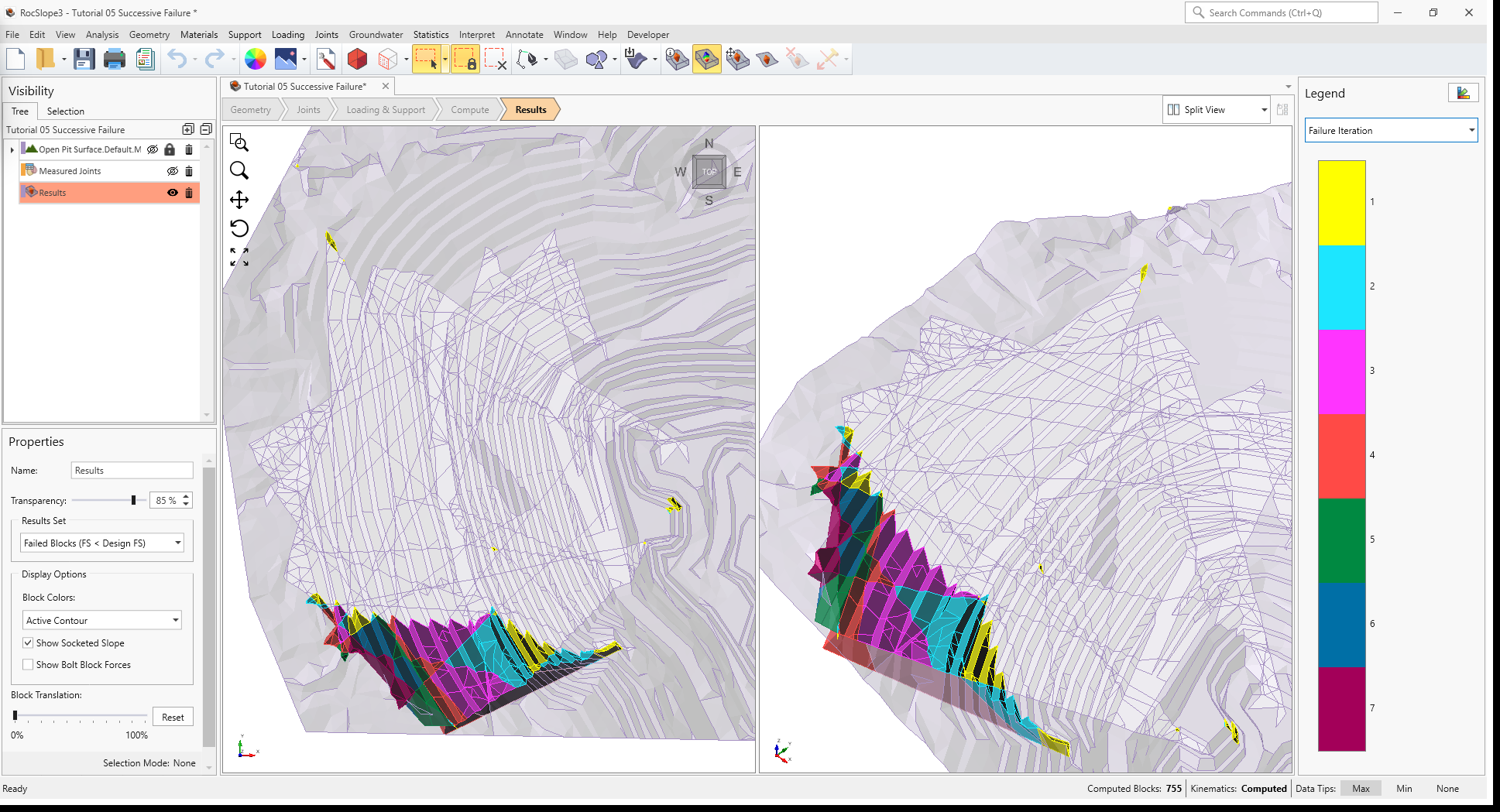
3D View of Failed Unit Blocks contoured by Failure Iteration - From the Contour pane on the right of the screen, select Failure Depth. The
daylighting unit blocks are contoured by the maximum Failure Depth, measured from the free surface
to the deepest failed unit block, in a direction normal to the free surface. This metric is a good indicator of the
minimum bolt length required to anchor into competent rock if bolts are installed normal to the slope surface.

3D View of Failed Unit Blocks contoured by Failure Depth
This concludes Tutorial 05.