Soil Profile Overview
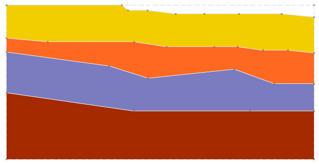
The Soil Profile option is an extension of geometry modelling capabilities. It allows you to define a master profile of your material boundaries (e.g. geological or soil profile) and ground surface. The profile is then used as a base template, over which you can use the regular boundary options (e.g. Add External, Add Material) to superimpose different slope geometries (e.g. cut back a slope).
The general procedure to use the Soil Profile option is as follows:
- Project Settings - First enable the Soil Profile checkbox in the Project Settings dialog.
- Profile Mode - a Profile workflow tab
 will appear, and the soil profile modelling options (e.g. Add Soil Profile Boundary, Borehole Editor) will be enabled in the menus and toolbar. To define or edit the Soil Profile, the Profile tab must always be selected. The Soil Profile Mode can also be selected from the Analysis menu.
 - Profile Extents - in the sidebar at the left of the screen, a Profile Extents input option will appear. This allows you to input the limits (left, right, top, bottom) of the Soil Profile region you wish to define. Input the desired limits, and the corresponding rectangular region will be highlighted by a dotted line.
- Profile Boundaries - you must then define the Soil Profile Boundaries. There are two methods of doing this:
- Boundaries can be explicitly defined using the Add Soil Profile Boundary option.
- Boundaries can be interpolated from borehole data using the Borehole Editor dialog.
Profile boundaries can represent material boundaries, the ground surface or other boundaries.
 workflow tab, to define the External Boundary of the slope you wish to analyze. There are TWO options for adding an External Boundary when you are using the Soil Profile option:
- The external boundary can be entered as a user-defined polyline, OR
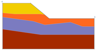
- The external boundary can be initially defined with a rectangular window, which is then used to "clip" the desired region of the profile, and the external boundary will be automatically generated from the clipped region.
In general, the External boundary should be contained within (or overlap) the Profile boundaries/extents, and should not be larger than the Profile Extents.
When Assign Materials from Profile on Change is enabled, Slide2 will automatically consider material types based on the soil profile whenever the geometry is modified (for example, when using Expand/Shrink External).
The Paste Materials from Profile option allows you to restore the material assignments to match the original soil profile.
Why Use a Soil Profile?
The Soil Profile option may be very useful for some modelling situations, and not useful or applicable for other modelling situations. Here are some guidelines:
- The Soil Profile option should be most useful for models with relatively complex material layering, over which you would like to define several different slope excavation scenarios. For example, an open-pit mine with several material layers, which is to be excavated or cut back in stages. The profile boundaries will remain constant, while you can define different slope boundaries (i.e. external boundary) over the profile.
- The Soil Profile option may not be useful for simple models, where the layering is simple and/or final geometry is fixed. In such cases, it is probably easier to define the entire model in Geometry mode, rather than first defining profile boundaries.
Soil Profile + Multi Scenario Modeling
In general, it may be helpful to use a Soil Profile in conjunction with Multi Scenario modelling, because the Multi Scenario option allows you to test different slope geometries by defining multiple models and changing the slope geometry for each model.
However, the Soil Profile option does NOT require the use of the Multi Scenario modelling feature of Slide2 and can be used independently.