New Pile Supports in RS2
New Pile Supports in RS2
by Daniel Wai
RS2 has improved the ability to model piles using the new dedicated Pile Support Type. Pile supports have a beam component for capturing the structural behaviour as well as an interface component to capture the soil-pile interaction behaviour, namely the skin and end bearing resistance. The new pile support formulation offers improved modelling of soil flow around a pile.
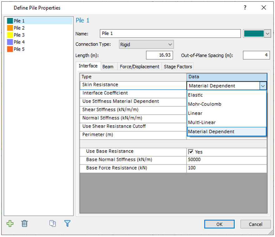
Before this feature was developed, pile behaviour was best captured using structural interfaces which, as the name suggests, also have structural and interface components. Pile properties would need to be converted to equivalent structural interface properties per unit out-of-plane. As shown in Figure 1, with the new dedicated pile support type, the user simply enters the pile properties and out-of-plane spacing. RS2 will take care of the rest. Furthermore, the user can define the pile-to-raft connection type (i.e. free, hinged, rigid, and semi-rigid) which are automatically applied when a pile intersects a liner. The user enters interface properties to define the skin and end bearing resistance. Various skin resistance models are available including Elastic, Mohr-Coulomb, Linear, Multi-linear and Material Dependent.
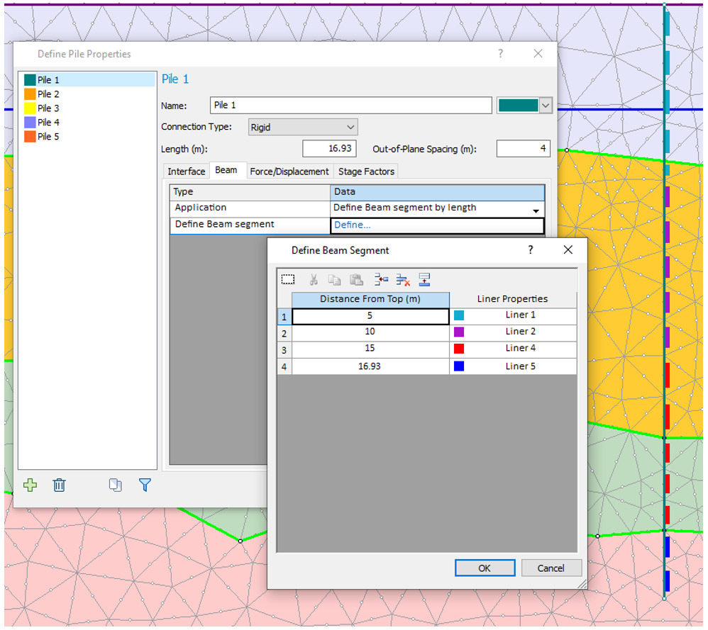
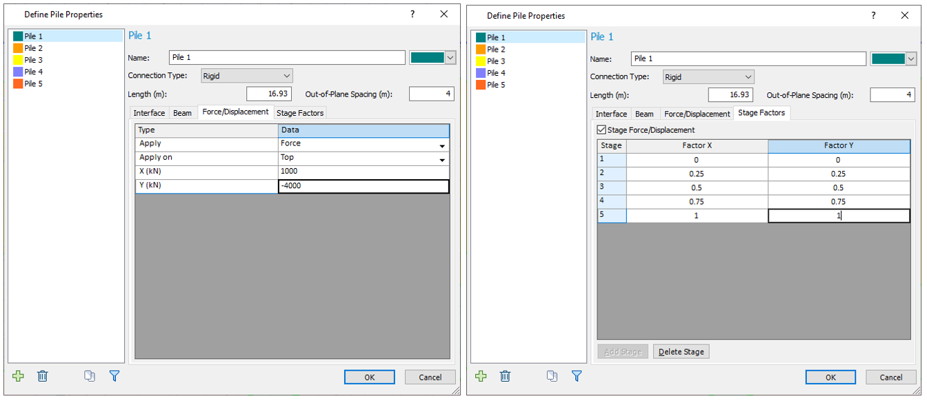
The beam component is defined using the familiar liner properties. The user has the choice of a constant liner property throughout the pile or to define beam segments by length. As shown in Figure 2, the Define Beam segment by length option allows different beam properties along the pile when the design requires multiple sections. As shown in Figure 3, the user can also add forces or displacements on the top or bottom of the pile which can be staged. This can be used for modelling the construction process or pile load tests.
Example: Piled Raft Foundation Design
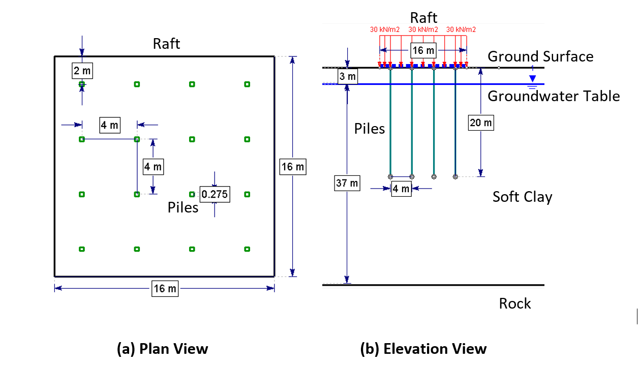
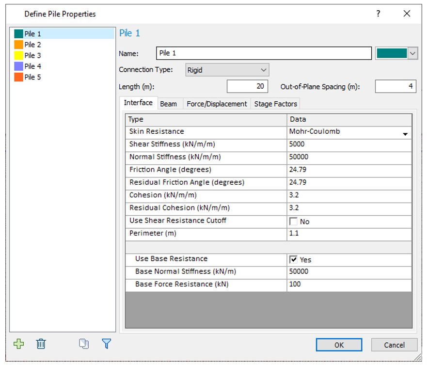
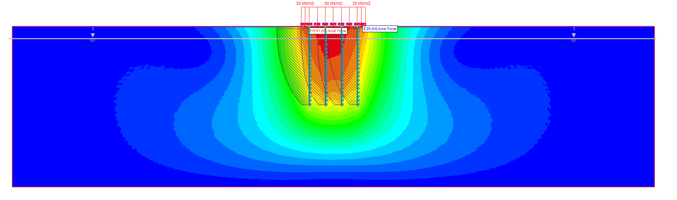
Figure 4 presents a piled raft foundation design. A uniform distributed load of 30 kN/m2 was applied to the piled raft built on a single clay layer. A firm rock layer is located directly under the clay, 40 m from the ground surface. A groundwater table is located 3 m below the ground surface. The 20 m long square pre-cast concrete piles are 275 mm in width and are installed with a 16 x 16 m2 raft. The piles are evenly spaced at 4 m. A Mohr-Coulomb skin resistance model is assumed for the interface behaviour. As shown in Figure 5, the pile properties can be directly entered into the new Define Pile Property dialog. Figure 6 presents the RS2 total displacement contours with pile axial force overlaid to show the performance of the pile raft foundation design. Full details on how to create the model can be found in our Piled Raft Foundation tutorial.
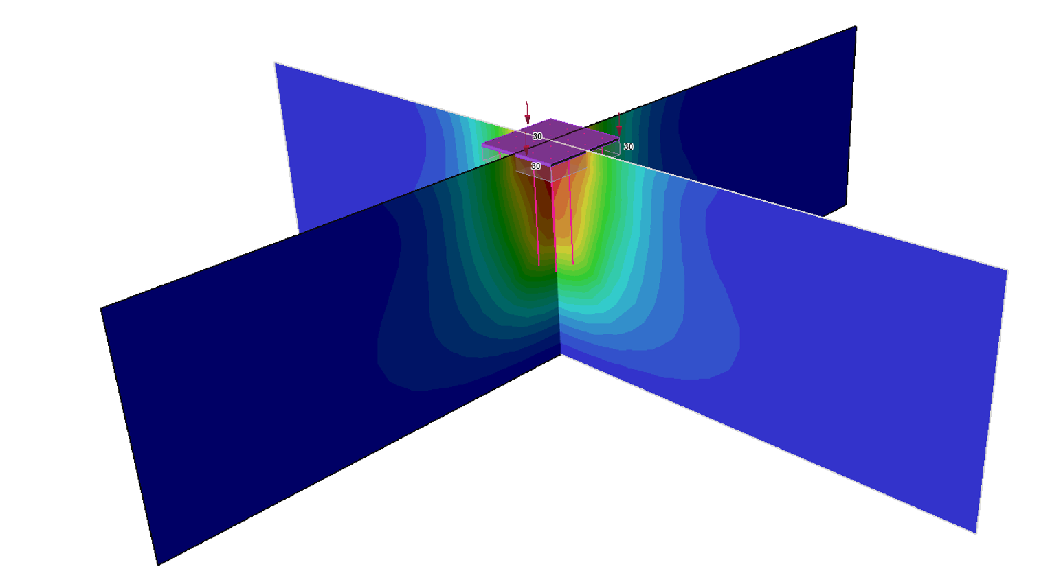
We can further improve the model by repeating the analysis in RS3 which can better capture 3D effects. Figure 7 presents the total displacement contours for the piled raft foundation design modelled in RS3 that shows similar deformations.