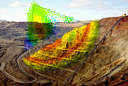
Launched Soil Nails in Slide2
As long-time users of Rocscience geotechnical analysis tools, the design-build teams at GeoStabilization International are excited about the many updates and improvements to Slide2, one of the most comprehensive slope stability analysis programs on the market. GeoStabilization engineers have been serving as beta testers of the new program, exploring the new features and capabilities. The inclusion of the “Launched Soil Nail” support type as one of the types available for designers in Slide2 will save engineers that design with these elements many hours of tedious iterations required in older design processes.
Launched Soil Nail Concept
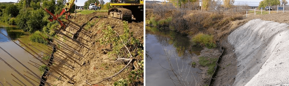
Launched soil nails are a proven technology that allows rapid stabilization of shallow landslides in soil. Tens of thousands of launched soil nails have been installed in the U.S., Canada, U.K., New Zealand, and Australia. Utilizing what has been termed as a “nail gun on steroids,” GeoStabilization and its partner companies launch soil nails into the ground to reinforce an unstable or potentially unstable soil mass by transferring the nail’s tensile and shear capacity into the sliding soil. These 1.5-inch-diameter, up to 20-feet-long nails are installed in a single shot using a compressed air “cannon” at velocities of up to 250 miles/hour, and at rates approaching 250 nails/day.
The single impulse, high-installation velocity creates a shock wave at the nail tip, which displaces the adjacent soil as the nail penetrates. The compressed air cannon induces tensile stresses in each tube as it penetrates the ground. This tension counteracts the compressive stresses induced by the displaced soil and thereby prevents nail buckling.
During most of the nail’s flight into the soil, the main frictional resistance occurs at the nail tip (not along its length) due to the elastic over-deformation of the soil induced by the rapid impulse. To demonstrate this phenomenon, paper stickers were placed on the outside of nails that were launched into a gravel pile, then later carefully exhumed. The stickers remained unabraded even after traveling up to 17 ft into the gravel. This phenomenon also explains the higher-than-expected bond strengths seen in launched soil nails versus driven soil nails. Like driven nails, the soil displaced by the nail densified (thus creating higher normal stresses along the nail shaft), but unlike driven nails, launched soil nails create minimal disturbance to the surrounding soil because of the rapidity of the single impulse. Consequently, launched soil nail unit bond strengths always exceed those of driven nails in the same soils, and often exceed those of conventional drilled soil nails using open-hole drilling techniques.
The typical launched soil nail consists of three parts:
- A perforated, hollow, galvanized outer tube with a specialized ballistic tip that is launched to full depth at pressures between 800-4,500 psi.
- Neat cement grout that is pressure injected into the hollow tube.
- An epoxy-coated inner reinforcing bar (typically a #6 bar) that is inserted before the grout sets.
Launched Soil Nail Applications
Primary applications of launched soil nails have been to stabilize shallow landslides, although the technology has been used to stabilize failing sheet/H-pile walls, for temporary shoring, for pipeline stabilization, and as micropile foundation supports for retaining walls. Launched soil nails have been used in a variety of soil and slope conditions, especially in mountainous areas, where rugged terrain limits construction options. Perforated tubes can be launched into landslide prone areas and left open to drain, producing the only commercially available elements that can both drain subsurface soil layers and provide axial and shear capacity in the same element.
Launched soil nails have been used on many notable projects and are credited with saving I-75 in Northern Tennessee from total collapse in 2005 and again in 2012 due to their speed of installation and ability to provide immediate structural contribution. In 2005, the use of launched soil nails for temporary embankment shoring prevented slope failure during excavation for the emergency installation of a rock buttress. Because the nails are effective seconds after installation, with no delay required for grout set, shoring of the slope could be conducted at the same rate as the slope excavation advanced without compromising worker safety. A few miles down the road in 2012, large cracks had developed in the southbound lanes as part of a large, active landslide. Within hours, both southbound lanes had failed and cracks were progressing into the northbound lanes. Emergency stabilization work commenced and, within 48 hours, over 250 launched soil nails were installed into the northbound lane and pressure grouted, which prevented scarp regression of the large landslide. With traffic on the northbound lanes safely restored, the southbound lanes could be stabilized with post-tensioned strand anchors and then reconstructed using a large rock buttress.
Launched Soil Nail Design
Launched soil nail design methodology is outlined in the joint USFS/FHWA Application Guide for Launched Soil Nails (EM 7170-12A/FHWA-FPL-93-003, July 1994) and relies on the theory that launched soil nails resist soil movement by acting in both tension and shear. In a drilled and grouted nail, by contrast, nail shear contributions are typically ignored. To understand this difference in design assumption, it is important to understand that unlike traditional drilled and grouted soil nails, launched soil nails have a much higher shear capacity to axial capacity ratio. Shear capacities of up to 20 percent or more of axial pullout capacity have been observed in launched soil nails (compared with typical values closer to 2 percent for traditional drilled and grouted nails). Because of this difference, the shear component of a launched soil nail is not ignored as it would be in traditional drilled and grouted soil nail design.
Although the structural capacity of the nail materials may be significant, the ultimate shear resistance of the nail is not controlled by the shear strength of the nail material, but by the ultimate bearing capacity of the soil in a localized area near the active failure surface. This localized bearing failure develops over a short section of the nail on either side of the failure plane, typically 3 ft or less. Typical shear resistance values range from 300-1,200 lbf.
Although the 1994 USFS/FHWA manual provides a detailed discussion of the equations and mechanisms behind launched soil nail capacity, the manual models shallow landslides and embankment failures as a planar sliding wedge, ultimately presenting simplified charts to determine nail spacing for various slopes. These charts, however, do not allow for non-uniform slopes, water tables, or slopes with non-uniform materials. If designers wished to model a slope that did not fit neatly into the charts, they were forced to employ a more tedious design method using equations from the USFS/FHWA manual, calculated by hand or spreadsheet, and then iteratively input into slope stability software using user-defined support models, updating with each stability analysis run until convergence.
Later federal guidance (GeoTechTools web-based information and guidance system (SHRP 2013) and Geotechnical Engineering Circular No. 7 Soil Nail Walls - Reference Manual (2015)) added to the discussion of launched soil nail design methodology and the mechanism by which they act. However, they did not outline a clear method for design that improved upon the 1994 USFS/FHWA calculations, leaving launched soil nail designers with a valid approach for design, but one that could take up to an hour to achieve convergence after running multiple iterations.
Launched Soil Nail Support Type in Slide2
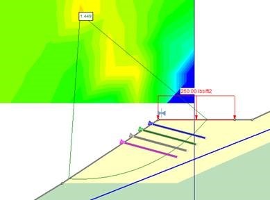
The creation and inclusion of the “Launch Soil Nail” support type in Slide2 culminates a years-long collaboration between Rocscience and GeoStabilization. The “Launched Soil Nail” support type in Slide2 allows the user to input the structural properties of the outer tube and inner reinforcing bar. It also allows the engineer to specify the resistance type the support provides - tensile, shear, or a combination of the two. Slide2 2018 uses the theory outlined in the USFS/FHWA manual to calculate the ultimate shear resistance, performing the calculations within the program code, thereby streamlining the analysis and reducing the opportunity for transposition errors between separate programs.
“We are excited that these updates to Slide2 allow designers to add this important tool to their geohazard mitigation toolbox,” states Roch Player, PE, GeoStabilization’s Chief Engineer. He continues, “by providing more options to the profession, the better we all can serve the public and protect them from the dangers of geohazards.”
References
Barrett, Colby and Graeme Quickfall (2016). “The Evolution of Launched Soil Nails.” GEOSTRATA, September/October 2016. pp 32-38.
Lazarte, Carlos, Helen Robinson, Jesús Gómez, Andrew Baxter, Allen Cadden, and Ryan Berg (2015). “Soil Nail Walls Reference Manual.” Geotechnical Engineering Circular No. 7, Report No. FHWA-NHI-14-007. National Highway Institute. Washington, DC.
SHRP (2013). “GeoTechTools.” www.geotechtools.org. accessed 2018.
USDA (1994). “Application guide for launched soil nails.” Volume 1. U.S. Department of Agriculture, Forest Service, Pub. EM 7170-12A and FHWA-FPL-93-003. Washington, DC, 63 p.