3D Finite Element Analysis of a Contiguous Pile Wall
By Ian Williams, Ph.D.
Introduction
This article provides a brief summary of a 3D finite element analysis carried out using RS3 to model a contiguous pile retaining wall at the site of a proposed commercial development in the UK.
The development site is located on sloping ground approximately 35 m from a motorway cutting. Due to the sloping topography of the site, cut and fill earthworks are to be undertaken to form a level development plateau upon which a large warehouse is to be built. This will require the construction of a circa 400 m long contiguous pile retaining wall to support the ground along the site’s upslope boundary where ground levels will be reduced by up to 8.4 m.
Wall Design
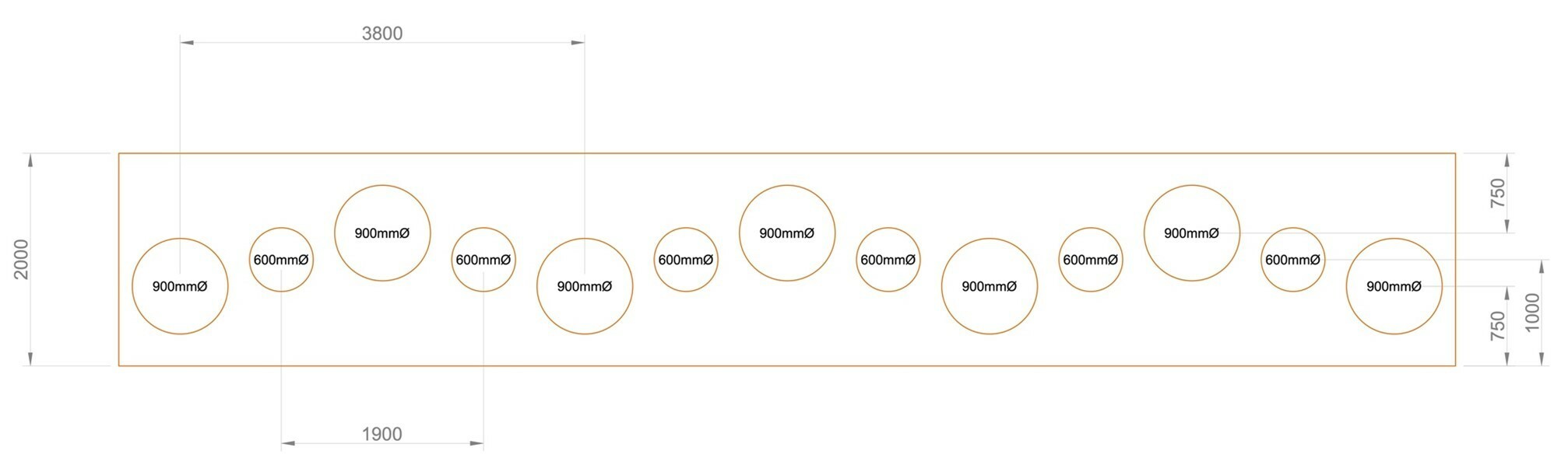
A plan showing the arrangement of the piles and the 2.0 m wide by 0.8 m deep capping beam is shown in Figure 1. The main 900 mm diameter piles are 17 m long and are staggered in a zigzag arrangement at 0.25 m offsets either side of the capping beam centreline. Interspersed mid-way between the main piles are 600 mm diameter infill piles. The infill piles are located along the capping beam centreline and are 11 m long.
Ground Conditions
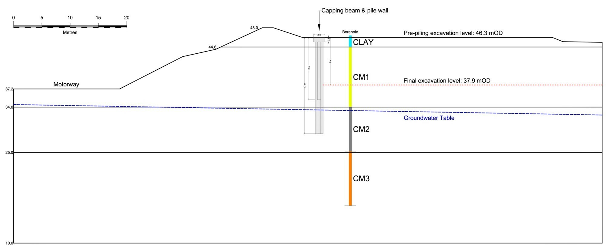
The ground conditions are summarised in Figure 2 which shows a 2D section perpendicular to the wall alignment at the location where the retained height attains its maximum value of 8.4 m. The succession of strata comprises a veneer of clay-rich Glacial Till overlying Coal Measures bedrock. The Coal Measures bedrock is dominated by siltstone and mudstone and has been divided into three geotechnical units (termed CM1, CM2, and CM3) based on strength, structure, and weathering characteristics.
The groundwater regime is hydrostatic with a phreatic surface dipping to the south and paralleling the contour of the original ground surface at a depth of around 14 m.
Finite Element Analysis
The objective of the RS3 analysis was to estimate long-term bending moments in the piles for comparison with design values derived using other software tools including FLAC3D.
A section through the RS3 model employed for the analysis is shown in Figure 3. Comprising 663,070 10-node tetrahedron elements, the model represents a 104 m long by 7.6 m wide slice through, and perpendicular to, the wall at the location where it attains its maximum retained height of 8.4 m.
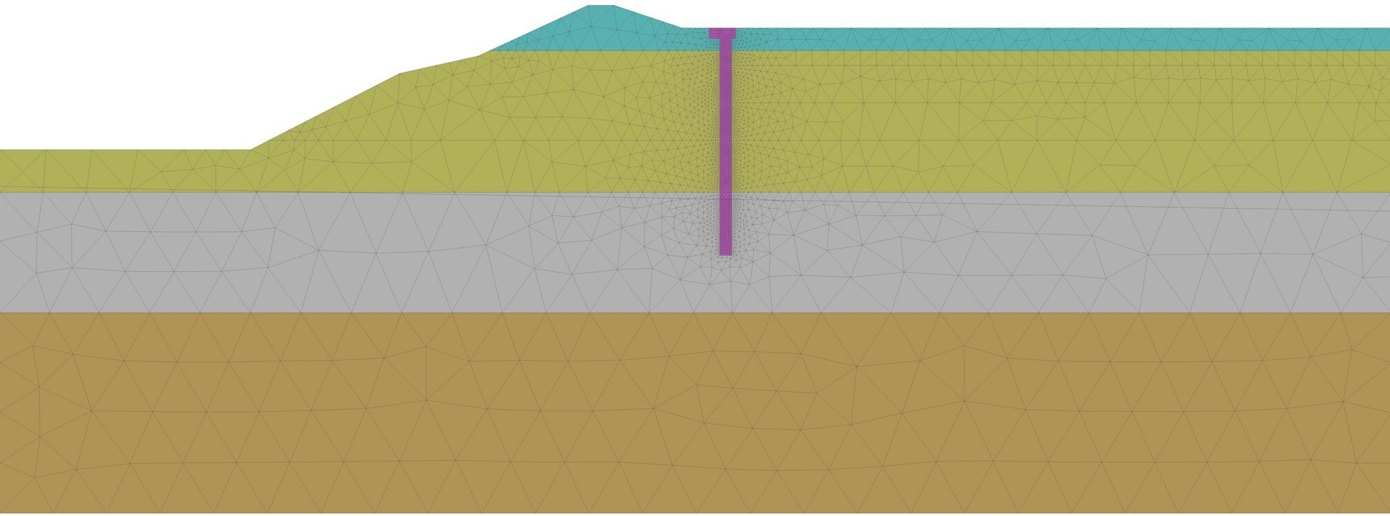
The Glacial Till and Coal Measures rock strata were represented using elastic-perfectly plastic constitutive models. The Mohr-Coulomb yield criterion was used for the Glacial Till and the Modified Hoek-Brown yield criterion was used for the Coal Measures rock strata. Fully drained conditions were assumed throughout.
The piles and capping beam were modelled as linear elastic with stiffness parameters representative of long-term conditions.
Interface characteristics at junctures between the ground and the retaining wall structure were modelled using elastoplastic joint elements to allow for relative movement parallel and normal to the interface surfaces.
The analysis was carried out in five stages as summarised below.
- Initialise the in-situ effective stress field.
- Construct the piles and capping beam.
- Excavate to 2.8 m depth, from 46.3 mOD to 43.5 mOD.
- Excavate to 5.6 m depth, from 43.5 mOD to 40.7 mOD.
- Excavate to 8.4 m depth, from 40.7 mOD 37.9 mOD.
Analysis Results
The results of the RS3 analysis are summarised in Figures 4 to 10.
Figures 4 to 6 show contours of horizontal, vertical, and total displacements respectively at the final stage of excavation. These figures show the development of an active wedge in the ground on the retained side of the wall. At the final stage of excavation, the lateral deflection at the top of the wall is around 93 mm.
The effect of the joint elements is evident in Figure 5 where the retailed can be seen to have moved down relative to the piles.
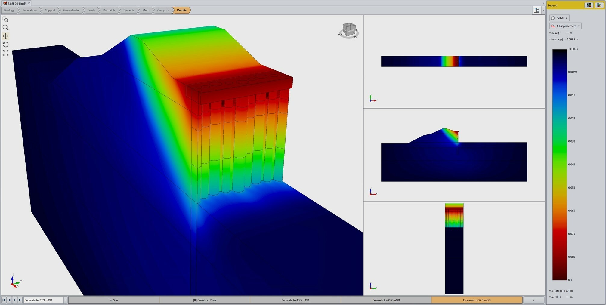
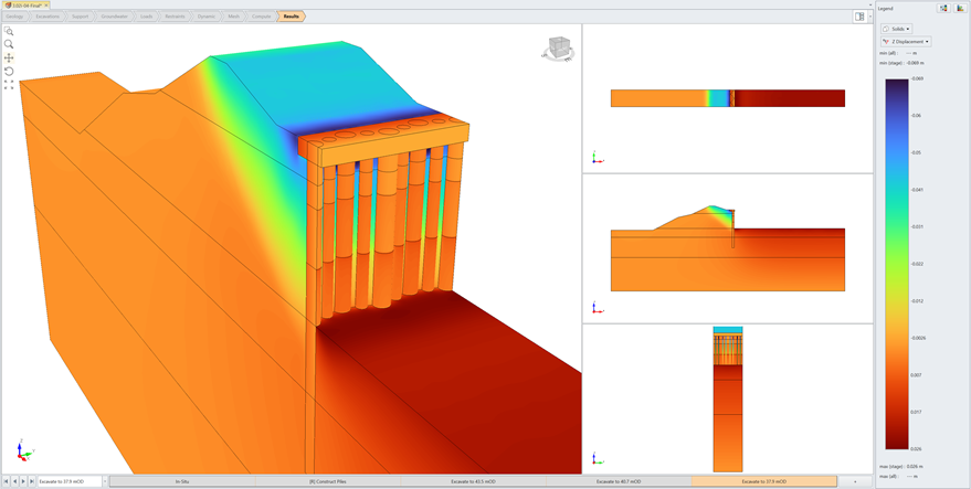
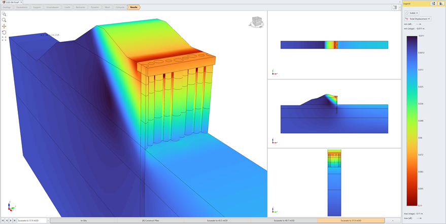
Figure 7(a) shows contours of vertical stress in the piles on the excavated face of the wall and Figure 7(b) shows contours of relative shear displacement between the piles and soil on the retained side of the wall.
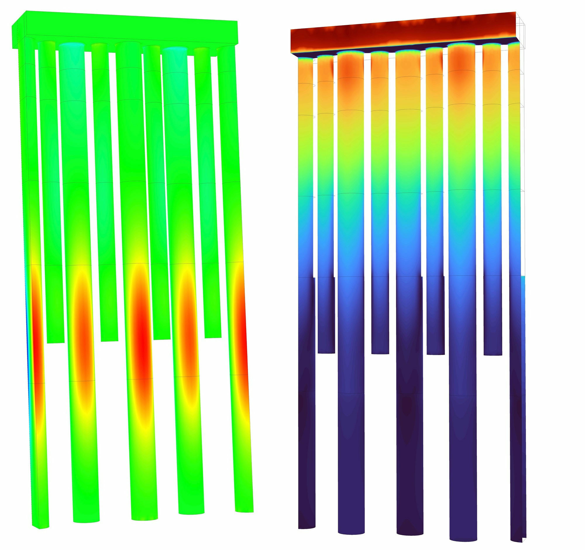
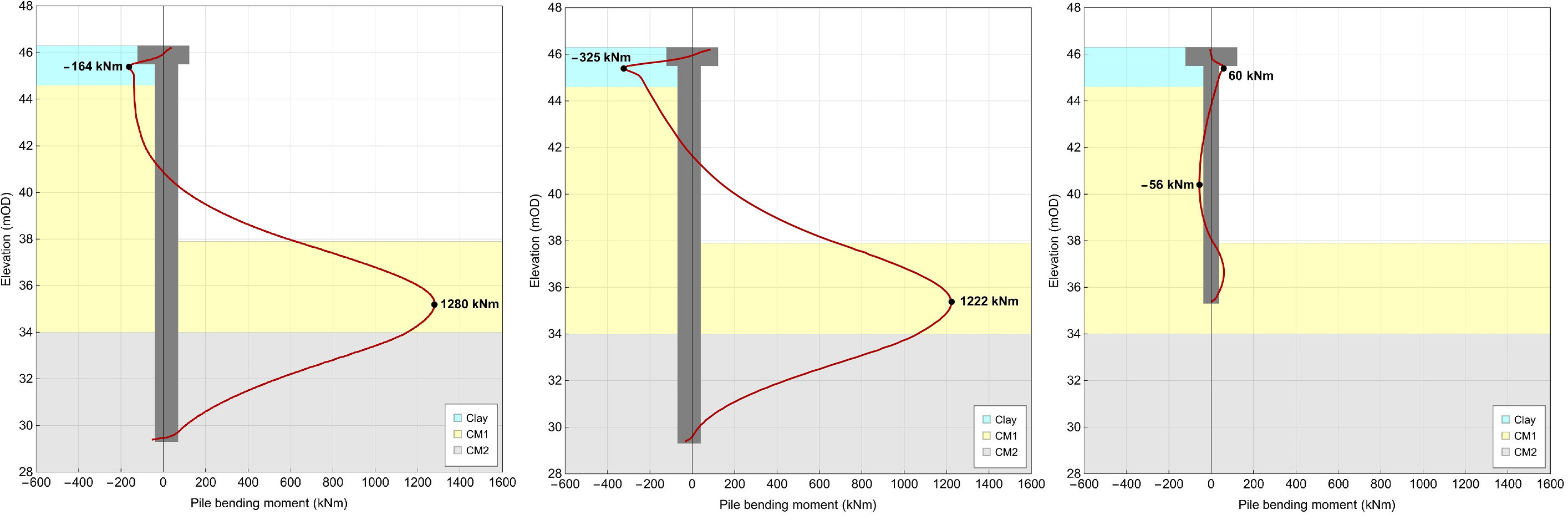
Figure 8 shows the pile bending moments at the final stage of excavation. The maximum bending moments are within 6 % of the design values derived from the FLAC3D analyses.
--