Joint Properties Overview
The SWedge analysis requires two (or three) distinct joint plane orientations to be defined. SWedge determines if a removable wedge can be formed by the intersection of the joint planes with the slope surface.
- If the Block Shape = Wedge then two joint planes can be defined (Joint 1 and Joint 2)
- If the Block Shape = Basal Joint then three joint planes can be defined (Joint 1, Joint 2, and Basal Joint)
To define the joint properties:
- Select Input Data
 from the toolbar or the Analysis menu.
 - Select the appropriate tab(s) in the Input Data dialog and enter the following joint properties:
- Optional Joint Properties - the following joint properties are optional, and can also be defined in the Input Data dialog:
Definition of Joint 1 and Joint 2
In SWedgethe two primary joint planes defining a wedge are referred to as Joint 1 and Joint 2. The SWedgeanalysis is formulated such that either joint plane can be defined as Joint 1 or Joint 2, this does not affect the solution. However, it is important to note that under the following circumstances, the Slope Height and the Tension Crack are measured with respect to Joint 1:
- If the slope face and upper face have different dip directions, this implies that the crest of the slope is not horizontal. In this case, the slope height (wedge height) is measured with respect to Joint 1 (see dimension H1 in the following figure).
- If the location of the Tension Crack is user-defined, then it is defined with respect to the trace length of Joint 1 from the crest (see dimension L in the following figure).
If either of these situations applies to your SWedge model, then you will have to keep this in mind when you define the Slope Height or the Tension Crack location.
Arbitrary wedge formed by the intersection of Joints (1 and 2) with Slope planes (3 and 4). Tension crack (5) is also shown. Slope height = H1. Joint 1 Trace Length (to define Tension Crack Location) = L.
Definition of Basal Joint
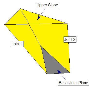
If the Basal Joint option is enabled, SWedge allows you to define an additional (third) joint plane referred to as the basal joint, as illustrated in the figure below. This allows you to analyze five-sided (pentahedral) wedges formed by the intersection of 3 joint planes and the 2 slope planes. An optional tension crack can also be defined for basal joint wedges, in the same manner as described above for tetrahedral wedges.
See the Block Shape and Basal Joint topics for further information.