Display Options
The Display Options  dialog allows you to customize various viewing and display options.
General Tab
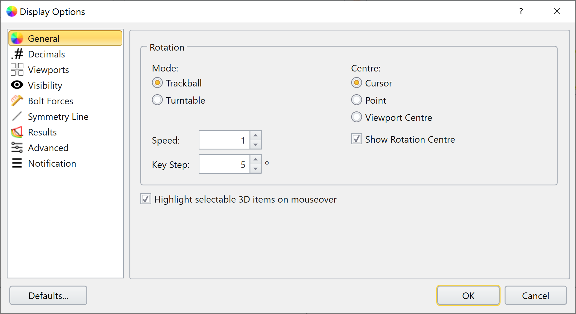
In this tab the user can define settings with respect to rotating the model. The user can select which Mode of rotation (Trackball, Turntable) and the Centre of rotation (Cursor, Point, Viewport Centre).
Turntable
With this option selected, the model is rotated in a manner analogous to a record spinning on a turntable.
Trackball
If this option is selected, the model is rotated in a manner analogous to a ball in the middle of the screen and dragging the mouse will roll this ball in the direction of the mouse.
Centre of Rotation
It is recommended for the user to enable the Show Rotation Centre to see how each of the options work:
- The Cursor option uses the cursor's location to determine the centre of rotation for the model.
- The Point option uses the origin as the reference point for rotation.
- The Viewport Centre option uses the current viewport's centre point as the reference with which rotation is done.
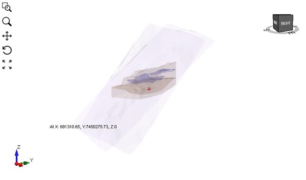
When Show Rotation Centre is turned on, the red center indicator will show at the center of the geometry view as you rotate the geometry (shown below):
The user can also change the sensitivity of the mouse by changing the Speed and Key Step.
The user should spend some time with these settings to become comfortable with the different rotation options.
Decimals Tab
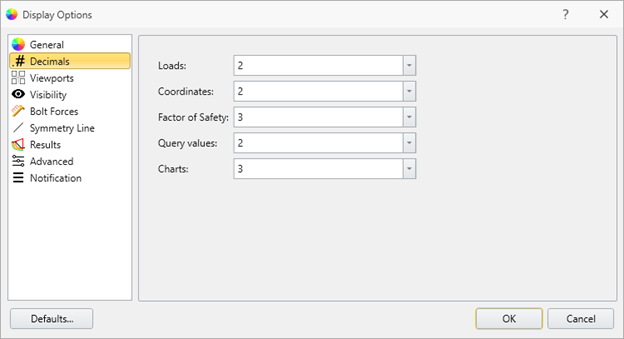
In this tab, the user can define the number of significant digits they wish to see for the following values:
- Loads
- Coordinates
- Factor of Safety
- Query Values
- Charts
This option is used primarily for model coordinates/ results.
Viewports Tab
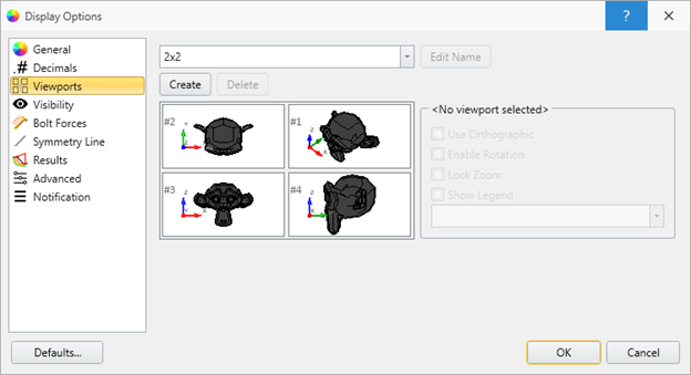
The viewport layout of a project can be changed by selecting an option from the dropdown menu at the top right of the document view. There are three views available: the 2x2 View, 3 Stacked View, and the Split Screen View.
The layout option can also be set in the display options menu, and can be set as the default setting by selecting Defaults > Make current settings default.
Please see the Viewports page for more details.
Visibility Tab
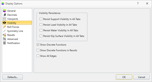
Persistence
In this tab you can change whether the following entities remain visible regardless of the workflow tab you are working in:
- Supports
- Loads
- Groundwater
- Slip Surfaces
You can also choose whether any Discrete Functions are displayed. It is recommended that the user take some time and determine the settings that best suit their needs.
Discrete Functions
The user can also choose whether they want values for any discrete functions to be visible.
The Show All Edges option allows the user to see the internal edges of the external geometry.
Bolt Forces Tab
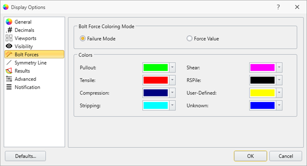
The user can decide whether to color based on either:
• Failure Mode
• Force Value
The user can also select the color for each of the failure modes.
Symmetry Line Tab
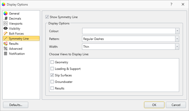
In this tab the user can customize the symmetry line, if one exists. You can change the Colour, Pattern and Width of the line. The user can also enable the symmetry line to be displayed in any of the workflow tabs (e.g. Geometry, Load & Support, etc.)
Results Tab
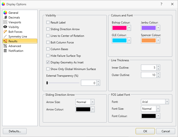
In this tab the user has a wide range of settings to customize the results and how they are displayed.
In the Visibility section, the user can enable/disable the following options:
In the Visibility section, the user can enable/disable the following options:
- Results Label – toggles the visibility of a label in the viewport attached to the global minimum surface, which displays the factory of safety.
- Sliding Direction Arrow – toggles the visibility of an arrow attached to the global minimum surface, pointing in the direction of failure.
- Lines to Center of Rotation – toggles the visibility of radial lines joining the axis point to the endpoints of the slip surface on the slope.
- Bolt Column Force – toggles the visibility of the bolt force of each bolt, displayed as an arrow at the end of each bolt. For more information, see Bolt Forces Tab section above.
- Column Bases – toggles the visibility of hatched lines on the slip surface which represent the base of each column.
- Hide Failure Surface Top – toggles the visibility of the geometry for the top surface of the failure surface, where the top surface can be defined as the area touching the top of the external.
- Display Geometry As Inset – toggles the display of the slip surface on the external between being shown as an opaque surface drawn on the external and being shown as a translucent surface where the entire shapes are visible.
- Show Only the Global Minimum Surface – toggles the visibility between showing just the slip surface geometry and showing the slip surface geometry within the defined external.
At the bottom of the Visibility section the user can also edit the transparency of the external geometry using the External Transparency slider.
You can also edit the Arrow Size and Colour in the Sliding Arrow section.
In the Colours and Font section, the user can select a colour for each method of calculation (Bishop, Janbu, etc.).
The user may also change the thickness of the failure surface outline in the Line Thickness section.
The FOS Label Font is where the user can change the colour, side, and font of the FOS.
Advanced Tab
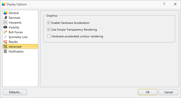
Enabling the Hardware Acceleration allows the program to use an external graphics card instead of an integrated graphics card.
Enabling the Use Simple Transparency Rendering speeds up the transparency rendering. This option is useful when the machine doesn't meet specifications and is too slow for more sophisticated models.
Enabling the Hardware accelerated contour rendering also speeds up the contour rendering. This option is useful when the machine doesn't meet specifications and is too slow for more sophisticated models.
Notification Tab
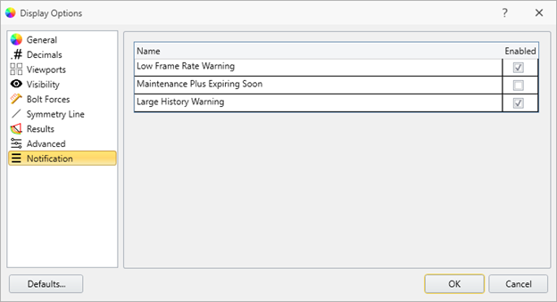
Enabling the notifications will allow the program to send the user warning messages for the following situations:
- Frame Rate is too low
- Maintenance + License Expiring soon
- Large History of operations done on an entity.