Grouted Tieback
The Grouted Tieback support type can be used to model support such as grouted tiebacks and ground anchors, which may have a variable bonded (grouted) length.
Bond Length
The bonded (grouted) length can be specified as either:
- a percentage of length
- actual bond length
Tensile Capacity
The Tensile Capacity entered for a Grouted Tieback, represents the maximum tensile capacity of an individual tieback. This is the capacity of the anchor tendon (i.e. steel tensile capacity), independent of the plate capacity or the bond capacity. Units are Force.
Plate Capacity
The Plate Capacity is the maximum load which can be sustained by the plate assembly which connects the tieback to the slope. Units are Force.
Shear Capacity
The Shear Capacity is optional and allows you to account for shear failure through the bolt cross-section (i.e. the force required to shear the bolt perpendicular to its axis). Units are Force. See below for implementation details.
Compression Capacity
The Compression Capacity is optional and allows you to account for the failure of the bolt in compression. This can be useful for modelling compression piles, for example. Units are Force. See below for implementation details.
Force Application
For Grouted Tieback support, the default method of Force Application = Active. See the Force Application topic for a discussion of the significance of Active and Passive support force application in Slide3.
Force Orientation
For Grouted Tieback support, the orientation of the applied force is PARALLEL to the orientation of the tieback, unless you are using the Shear Capacity option, in which case the force may be applied at some angle to the bolt axis, corresponding to the resultant of the shear and tensile components (see below for details).
Pullout Strength
For a Grouted Tieback, the Pullout Strength is simply expressed as a Force per unit Length.
Material Dependent Pullout Strength
The Material Dependent checkbox allows you to define the Pullout Strength of a Grouted Tieback, according to the material(s) which the bonded length of a tieback passes through. In order to use this option:
- Select the Material Dependent checkbox, and select the Define button.
- You will see the Pullout Strength dialog. In this dialog, select the Add
 button, for each material that you wish to define the Bond Strength for.
 - For each material, use the mouse to select a Material Name, and enter a value for the Bond Strength. (NOTE: the Material Names correspond to the materials you have defined in the Define Material Properties dialog).
- Any material which you have NOT included in the Pullout Strength dialog, will use the Bond Strength value which you have entered in the Define Support Properties dialog.
- When you are finished customizing the Bond Strength for all the required materials, select OK in the Pullout Strength dialog.
Implementation of Grouted Tieback Support in Slide3
The Grouted Tieback properties which are entered in the Define Support Properties dialog, are used to determine a Force Diagram for a Grouted Tieback, as described below.
Consider a grouted tieback, which intersects a slip surface, as shown below (diagram is 2D but the actual implementation is 3D).
Li = bonded length of tieback within sliding mass
Lo = bonded length of tieback embedded beyond slip surface
Tieback Parameters:
B = Bond Strength (force / unit length of bond)
T = Tensile Capacity (force)
P = Plate Capacity (force)
For a Grouted Tieback, at any point along the length of the tieback, there are 3 possible failure modes which are considered:
- Pullout (force required to pull the length Lo of the tieback out of the slope)
- Tensile Failure (maximum axial capacity of the tieback tendon)
- Stripping (slope failure occurs, but tieback remains embedded in slope)
The maximum force which can be mobilized by each failure mode is given by the following equations:
Pullout:  Eqn.1
Eqn.1
Tensile: ![]() Eqn.2
Eqn.2
Stripping: ![]() Eqn.3
Eqn.3
At any point along the length of the tieback, the force which is applied to the slip surface by the tieback is given by the MINIMUM of these three forces.
Applied Force = min (F1, F2, F3) Eqn.4
- In order for stripping to occur, the Plate Capacity must be exceeded. The Plate Capacity is included in the stripping force equation and added to the bond shear capacity along the length Li.
- If the tieback Bond Strength is specified as Material Dependent, then the Pullout Force and Stripping force, are determined by integrating along the bonded length, to determine the force contributed by each segment of the bonded length which passes through different materials.
A Force diagram for a Grouted Tieback, which exhibits all three failure modes, is shown below. In this case, the Plate Capacity is less than the Tensile Capacity, and therefore "stripping" is a possible failure mode. If the Plate Capacity is greater than the Tensile Capacity, then stripping cannot occur, and the Force diagram will be determined only by the Tensile and Pullout failure modes.
Implementation of Shear Capacity
If the Shear Capacity option is selected, an additional force vector perpendicular to the bolt direction, and opposite to the direction of failure, is added to the overall bolt capacity vector, determined by the methods described above. You’ll see this in Results mode when you show the support data. The support force at the base of the column is no longer parallel to the support but angled in a direction opposite to the slip direction. The Shear Capacity option may be useful if you expect that the support forces are not purely tensile, but may include a transverse shear component as well. This depends on the orientation of the support relative to the slip surface direction (diagram is 2D, the actual implementation is 3D).
Implementation of Compression Capacity
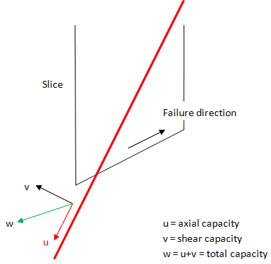
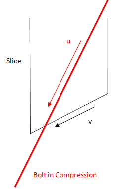
If the Compression Capacity option is selected, the bolt can apply a stabilizing force to the slope when it goes into compression. This can be useful for modelling compression piles, for example. To determine when a bolt goes into compression, the program looks at the direction of displacement at the point where the bolt crosses the failure surface. The direction of displacement is equal to the direction of the base of the column through which the bolt traverses, as shown in the figure below. If the dot product of vector u and v is positive, the bolt is in compression (diagram is 2D, the actual implementation is 3D).
If the bolt goes into compression, the capacity is determined in the same way as a bolt-in tension, with the following two differences. The first is the compression capacity is substituted for the tensile capacity. The second is that the plate capacity is assumed to be zero. Three modes of failure are still examined to determine the overall capacity. The first is compression failure of the tendon. The second is the bond failure of the bolt outside the failed mass. The third is the bond failure of the bolt internally to the failed mass. The overall capacity is simply the minimum of these three failure modes, as described above for the tensile failure mode.