Add Elevation Load
Elevation distributed loads, which vary linearly between two points of different elevation (i.e. the z-coordinate of each point differs) along a boundary, can be applied to edges or faces with the Add Loads option and specifying Elevation Load as the Load Type. The load distribution is treated as triangular (zero at one end) or trapezoidal (different non-zero values at each end) based on the user-specified Top Magnitude/Delta and the elevation of the boundaries.
To apply an Elevation distributed load by projecting a region onto geometry:
- Select the Loading & Support
 workflow tab.
 - Select Add Loads
 from the toolbar or the Loading menu.
 - You will see the Add Load dialog. In this dialog:
- Select the Load Type = Elevation Load
- Enter the Top Magnitude / Delta of the load
- Specify the load Orientation (e.g. Normal, Local +x, Local +y, Local +z, Vector (x,y,z), or Trend/Plunge)
- Specify location and orientation of the load region
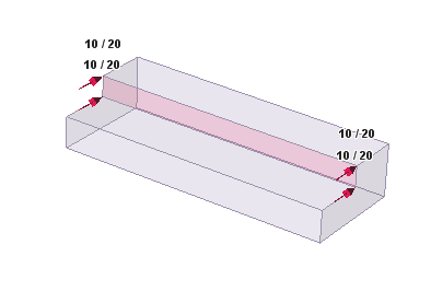
- When finished specifying the load properties and the preview of the applied load, select OK. The Elevation distributed load will be applied to the selected face(s), as indicated by the display of red arrows and the magnitude.
- Check the direction of the arrows and the magnitude, to make sure that this is the load you wished to apply. If there is a mistake, you can select Undo and repeat the above steps to apply the correct load, or select and edit the load using the Properties Pane to change the load parameters.
See below for details about the load magnitude and orientation.
To apply an Elevation distributed load to a face:
- Select the Loading & Support workflow tab.
- Select Faces Selection
 as the Selection Mode.
 - Select face(s) on which to apply the load.
- Select Add Loads Selected from the toolbar or the Loading menu. TIP: with the face(s) selected, you can also right-click on the viewing screen and select Add Loads from the Loading sub-me
- You will see the Add Load dialog. In this dialog:
- Select the Load Type = Elevation Load
- Enter the Top Magnitude / Delta of the load
- Specify the load Orientation (e.g. Normal, Local +x, Local +y, Local +z, Vector (x,y,z), or Trend/Plunge)
- When finished specifying the load properties and the preview of the applied load, select OK. The Elevation distributed load will be applied to the selected face(s), as indicated by the display of red arrows and the magnitude.
- Check the direction of the arrows and the magnitude, to make sure that this is the load you wished to apply. If there is a mistake, you can select Undo and repeat the above steps to apply the correct load, or select and edit the load using the Properties Pane to change the load parameters.
See below for details about the load magnitude and orientation.
To apply an Elevation Load to an edge (line load) repeat Steps 1 to 7, but use Edges Selection ![]() to select the edge(s) on which to apply the load.
to select the edge(s) on which to apply the load.
Top Magnitude / Delta of Load
The Top Magnitude is the magnitude of the load that will be applied at the top, or the highest point, of the selected boundary (edge or face). The Delta is the change in the load magnitude per unit decrease in elevation.
- Delta = 0 means that the magnitude of the load does not change with a decrease in elevation (z-coordinate). This type of Elevation Load is equivalent to a Uniform Load.
- Delta > 0 means that the magnitude of the load increases as the elevation of the boundary decreases (i.e. the load magnitude at the bottom of the boundary is greater than the Top Magnitude).
- Delta < 0 means that the magnitude of the load decreases as the elevation of the boundary decreases (i.e. the load magnitude at the bottom of the boundary is less than the Top Magnitude).
Load Magnitude
A distributed load magnitude is generally entered as a positive value. The direction of the load application is specified by selecting an appropriate Orientation method (see below) in the Add Load dialog. If a negative load magnitude is entered, the direction of the applied load will be reversed.
Load Orientation
For details about defining the load Orientation, see the Uniform Load topic, as the same information applies to both Uniform and Elevation loads.