24 - FOS for Geosynthetic Reinforced Retaining Wall
1.0 Introduction
For a reinforced retaining wall, it is crucial to evaluate the safety factor of a critical failure surface that either goes through or extends outside the wall.
In this tutorial, we will model a geosynthetic reinforced retaining wall in Slide2. The tutorial will help you to become familiar with accessing and using the Manufacturer Library (for support types such as Geotextiles, Geogrids, and Strips) in Slide2.
Topics Covered in this Tutorial:
- Adding Geosynthetic Supports to a retaining wall
- Slip Surface Boundaries
- Cuckoo Search (non-circular surface search)
- Support Forces
- Minimum Factor of Safety
Finished Product:
The finished product of this tutorial can be found in the Tutorial 24 Geosynthetic Retaining Wall.slmd data file. All tutorial files installed with Slide2 can be accessed by selecting File > Recent Folders > Tutorials Folder from the Slide2 main menu.
2.0 Model
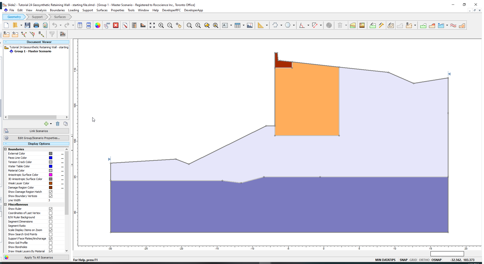
- Select File > Recent Folders > Tutorials Folder and open the file Tutorial 24 Geosynthetic Retaining Wall - starting file.slmd.
2.1 Material Properties
The model consists of five materials.
- Go to Properties > Define Materials
 to see the materials and their properties in the Material Properties dialog. Four materials have been defined in the model: Wall, Backfill, Glacial till, and Facing.
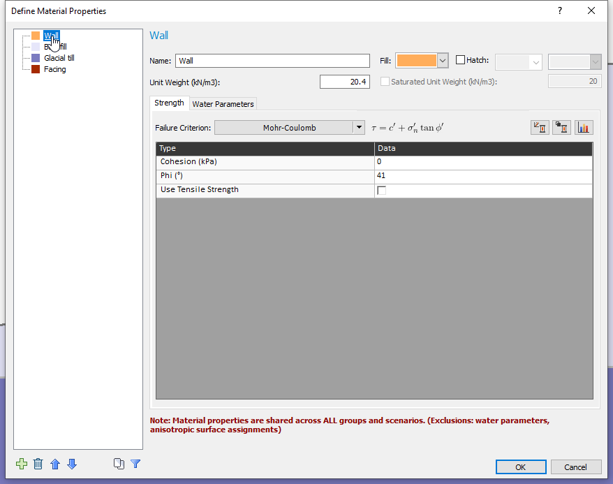
- Click OK or Cancel to close the dialog.
3.0 Define Support Properties
We will define 3 types of Geosynthetic Supports in this model. The two main properties that determine the strength of such supports are the tensile and pullout strength.
To specify the strength properties of the Geosynthetic support:
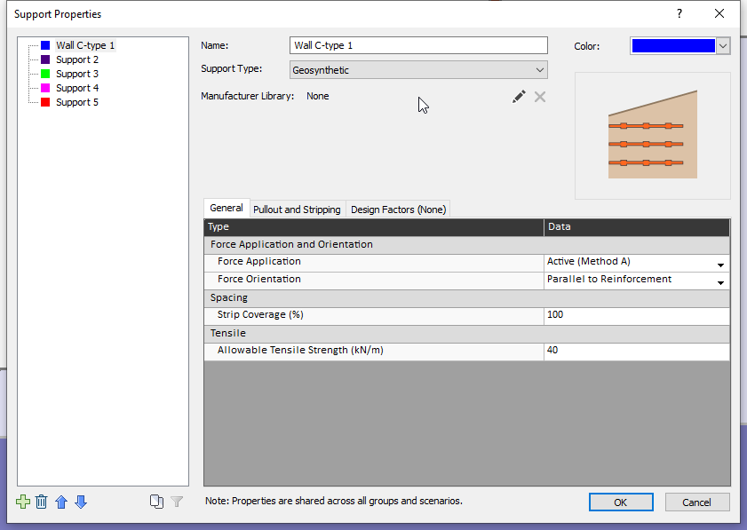
- Go to Properties > Define Support
 to open the Support Properties dialog.
 - Select Support 1 and rename it as Wall C-Type 1.
- Under the Support Type dropdown, select Geosynthetic.
- Click on the Edit (pencil)
 icon beside Manufacturer Library to open the Manufacturer Library dialog.
 - In this dialog, select the options shown below:
- Manufacturer = Tensar
- Production Set = Tensar RE (Africa, Asia, Australia, Europe)
- Type = Tensar RE580
- Change the Deterioration in Service Factor (RFd) parameter to 1.1.
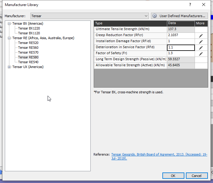
- Click OK to close the Manufacturer Library dialog.
- In the Support Properties dialog, select the following under the General tab:
- Force Application = Passive (Method B)
- Force Orientation = Parallel to Reinforcement
- Strip coverage = 100%
- Next, click on the Pullout and Stripping Tab and enter the following:
- Anchorage
- Anchorage = Slope Face
- Connection Strength Input = Constant
- Connection Strength (kN/m) = 40
- Shear Strength of Interface
- Input Type = Coefficient of Interaction
- Coefficient of Interaction = 1
- Material Dependent = No
- Use external loads in strength computation = Yes
- Enter the properties given in the table below. Leave the other options with default settings.
- Click OK to close the Support Properties dialog after defining all supports.
The default values for this support are displayed on the right-hand side of the dialog.
The Long-Term Design Strength (according to the selected support type) is automatically populated. Leave all other parameter values as defaults.
We will now define the remaining two supports, Wall C-type 2 and Wall C-type 3, following the same procedure as Wall C-type 1.
Name |
Support 2 |
Support 3 |
|||
Wall C-type 2 |
Wall C-type 3 |
||||
Support Type |
Geosynthetic |
||||
Manufacturer Library |
Manufacturer |
Tensar |
|||
Production Set |
Tensar RE (Africa, Asia, Australia, Europe) |
||||
Type |
Tensar RE560 |
Tensar RE520 |
|||
Deterioration in Service Factor (RFd) |
1.1 |
||||
General Tab |
Force Application |
Passive (Method B) |
|||
Force Orientation |
Parallel to Reinforcement |
||||
Long Term Design Strength (kN/m) |
Automatically calculated |
||||
Strip Coverage (%) |
100 |
||||
Pullout Strength |
Anchorage |
Slope Face |
|||
Connection Strength Input |
Constant |
||||
Connection Strength (kN/m) |
40 |
||||
Input Type |
Coefficient of Interaction |
||||
Coefficient of Interaction |
1 |
||||
Material Dependent |
No |
||||
Use External Loads in Strength Computation |
Yes |
||||
We will now add the support patterns.
4.0 Support Pattern
- Go to Support > Add Support Pattern
 to open the Support Pattern dialog.
 - Enter the following:
- Support Property = Wall C-type 1
- Orientation = Horizontal
- Support Length = 9 m
- Distance between support = 0.6 m
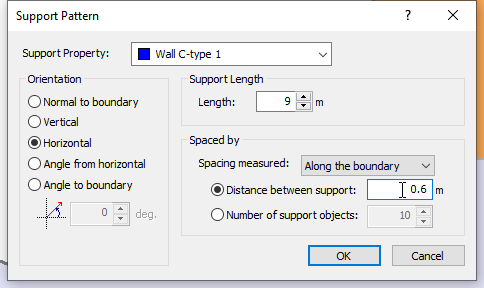
- Click OK to close the dialog.
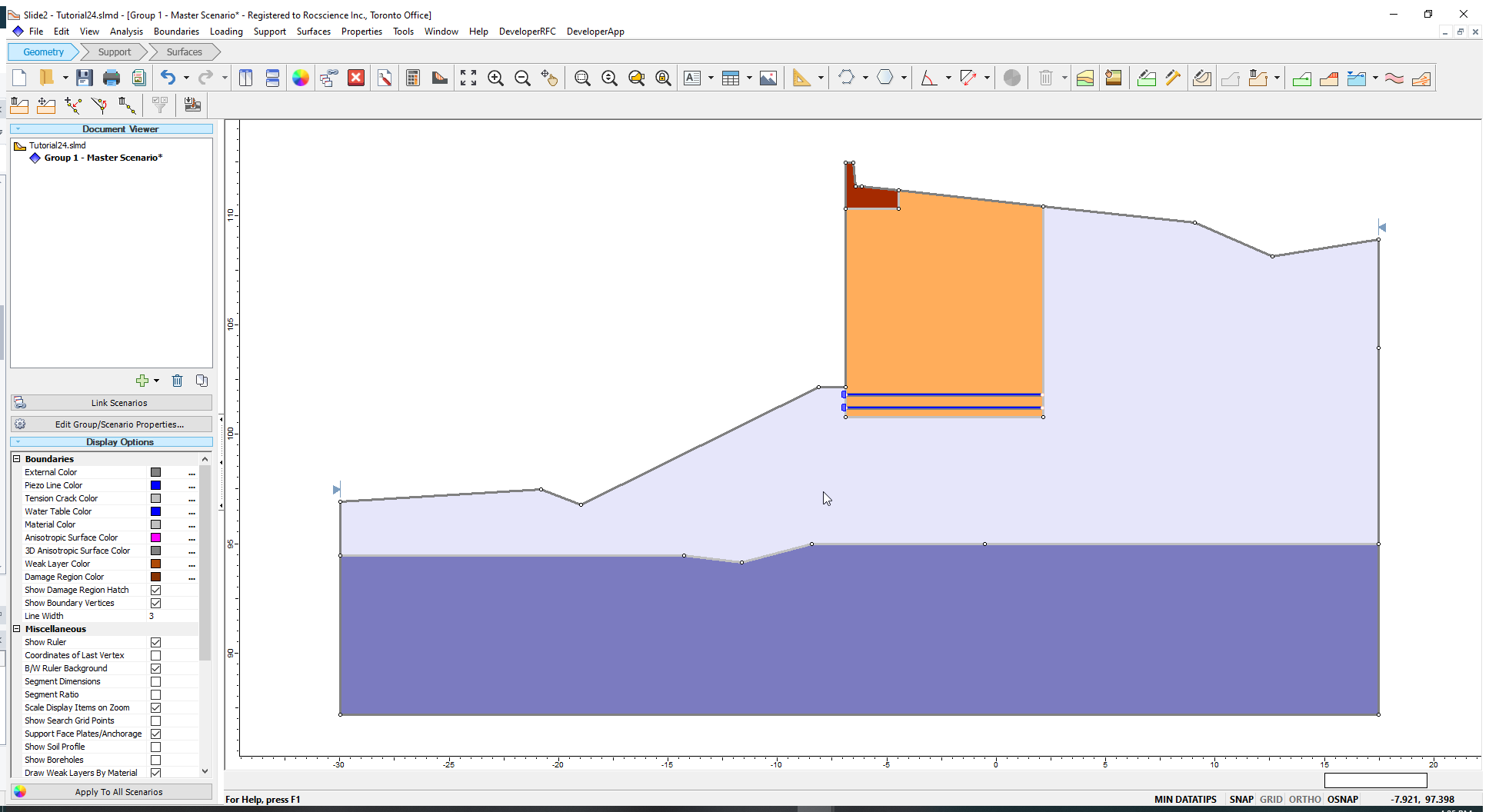
- Enter the coordinates ( -6.896, 101.2) in the Prompt line and press the ‘Enter’ key. The first geosynthetic support is added.
- A geosynthetic support will be positioned at the entered coordinates. It is anchored at the left edge of the Wall (orange). As you move the mouse above the first support, second support will appear on top of it as shown in the following figure:
- Select Support > Add Support Pattern in the menu. The Support Pattern dialog will open. All factors should stay the same as the first time. Select OK to close the dialog.
- You now should see a cursor on the screen. With the Prompt line now activated, enter coordinates = (-6.896, 102.4) and press the ‘Enter’ key.
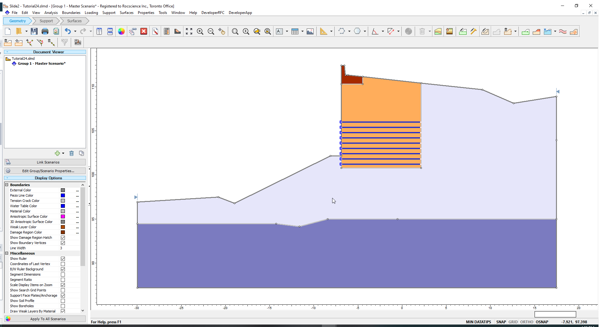
- Move the mouse above the second support and add a total of seven supports as shown below. Left-click with your mouse to place the supports.
- Open the Add Support Pattern dialog and enter the properties below.
- Support Property = Wall C-type 2
- Orientation = Horizontal
- Length = 9 m
- Distance between support = 0.6 m
- Click OK to close the dialog.
- Enter the coordinates (-6.896, 106.6) and position four supports above Wall C-type 1.
- Open the Add Support Pattern dialog again and enter the properties below for Wall C-Type 3.
- Support Property = Wall C-type 3
- Orientation = Horizontal
- Length = 9 m
- Distance between support = 0.6 m
- Click OK to close the dialog.
- Enter coordinates (-6.896, 109.0) and position three supports above Wall C-type 2.
You will see the cursor (displayed as a red cross) on the screen. We must determine the position of the supports.
The spacing between the two supports is 0.6 m. Supports further above the two supports cannot be extended because a boundary vertex is within 0.6 m above the second support. Left click with your mouse to complete placing the supports. To build the rest of the supports, we need to add a second support pattern.
Just as you did for Wall C-Type 1, add Wall C-Type 2 and Wall C-Type 3 supports.
Your model should look like below.

5.0 Slip Surface Boundaries
To evaluate slip surface failure that involves the retaining wall, we will define a secondary set of limits.
- Right-click on the primary slope limit and select Define Limits
 (or select Surfaces > Slope Limits > Define Limits).
 - In the Define Slope Limits dialog, check the box for Second set of Limits.
- Enter the below coordinates for the Limits and Second set of limits:
- Limits
- Left x coordinate: -29.989
- Right x coordinate: -8.111
- Second set of limits
- Left x coordinate: -4.471
- Right x coordinate: 17.481
- Click OK to close the dialog.
Now a secondary set of limits is displayed. Your model should look like this:
6.0 Surface Options
- Go to Surfaces > Surface Options

- Select ‘Non-Circular’ and then ‘Cuckoo Search’ method. All other options remain at the default values.
- Click OK.
Now let us compute the analysis.
7.0 Computation and Interpretation
- Run the analysis (Analysis > Compute
 ) and Interpret (Analysis > Interpret
  ) when computations are done.
The Global Minimum slip surface for Janbu and Spencer can be seen. View the Spencer results:
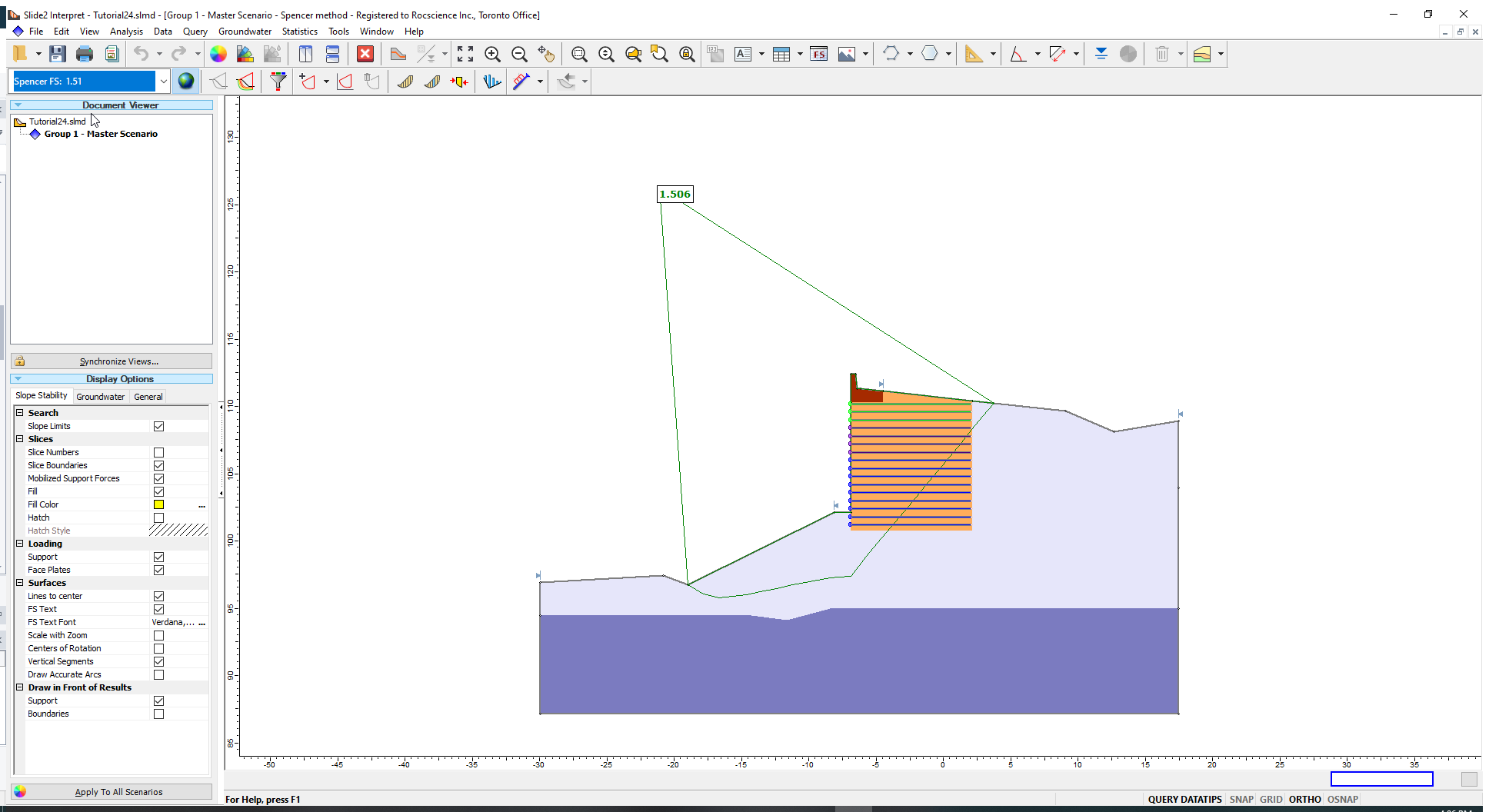
- Click on the Show Support Force Diagram
 icon to display the force for each support.
Notice that the tensile failure mode takes precedence along most of the support – the tensile forces correspond to the Long Term Design Strengths. The stripping and pullout forces take precedence on the ends of the support as expected.
- Click the button again to turn off the Support Force Diagram.
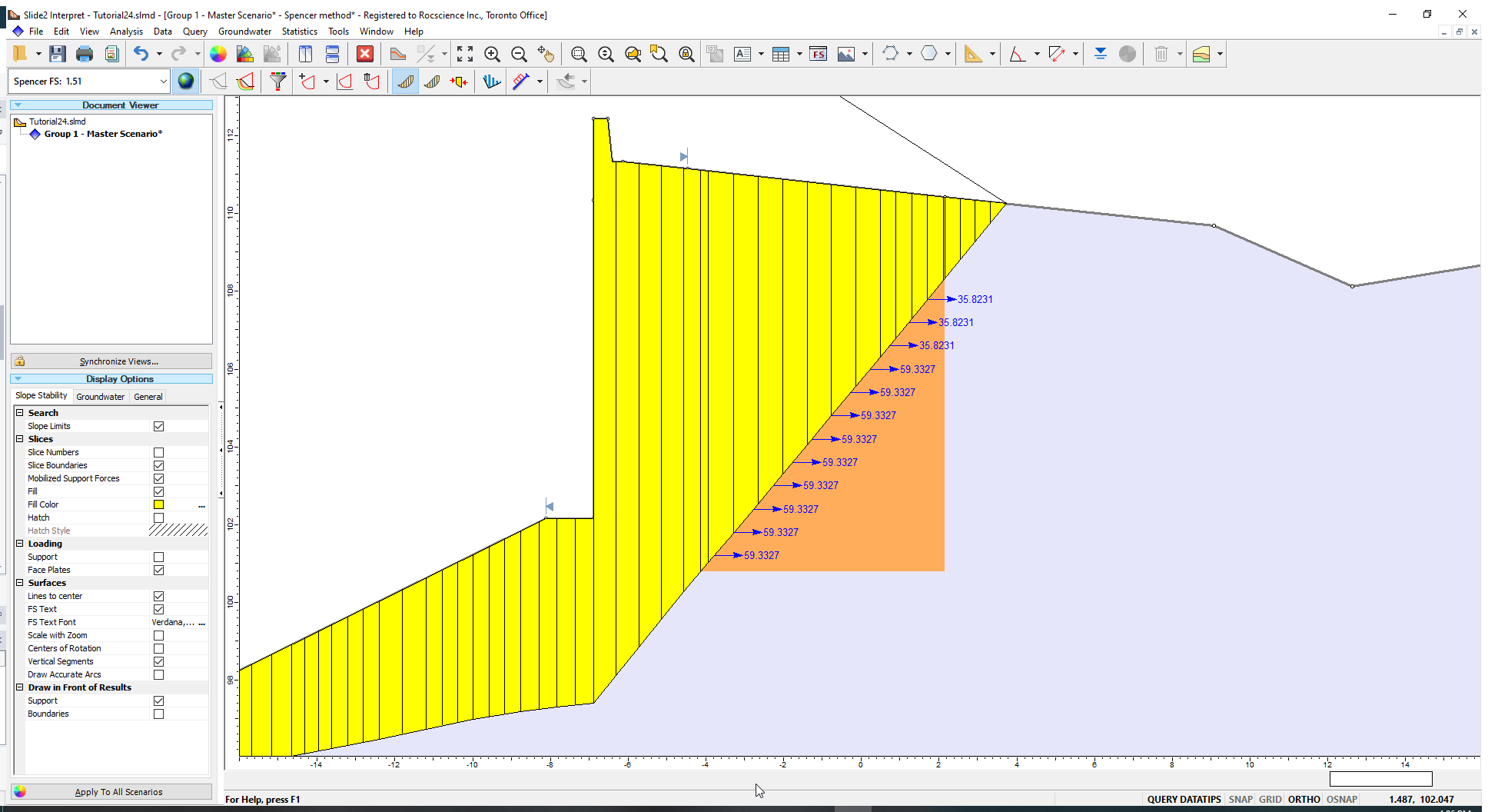
- Select Query > Show Slices

The exact forces applied to the intersecting slices are shown. The intersecting force corresponds to the force in the support force diagram which occurs at the point where the slip surfaces intersects the support.
- To better visualize this, in Display Options on the lefthand side, uncheck Support. Alternatively select View > Display Options
 and uncheck Support from there.
The support forces applied to each slice are shown below:
This concludes the tutorial.