4 - Wick Drain Tutorial
1.0 Introduction
Topics Covered in this Tutorial:
- Embankments
- Multiple Materials
- Time-Dependent Consolidation Analysis
- Wick Drains
Finished Product:
The finished product of this tutorial can be found in the Tutorial 04 Wick Drains.s3z file. All tutorial files installed with Settle3 can be accessed by selecting File > Recent Folders > Tutorials Folder from the Settle3 main menu.
2.0 Model
If you have not already done so, run Settle3 by double-clicking on the Settle3 icon in your installation folder. Or from the Start menu, select Programs > Rocscience > Settle3.
2.1 Project Settings
- Select Home > Project Settings
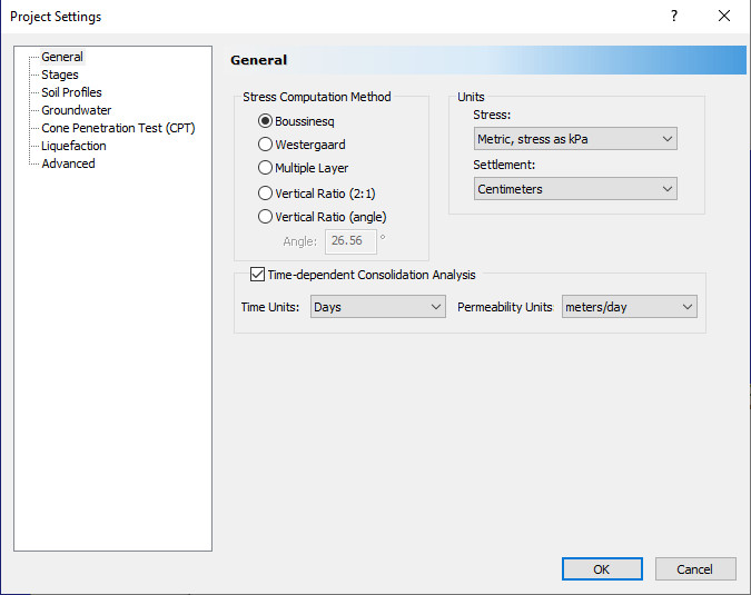
 and make sure the General tab is selected.
 - Set the Stress units = Metric, stress as kPa, and the Settlement units = Centimeters.
- Select the Time-dependent Consolidation Analysis checkbox.
- A message will appear informing you that the groundwater analysis option will be turned on because it is required for consolidation analysis. Click OK to close the warning.
- Set the Time Units = Days and Permeability Units = meters/day.
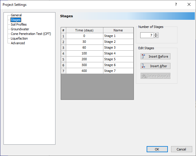
- Click on the Stages tab. Set the Number of Stages = 7 and fill in the stage times as shown.
- Select Soil Profiles tab. Select 'Depth below ground surface' option.
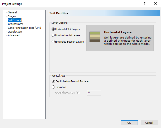
- Click OK to exit the dialog
| # | Time (Days) | Name |
| 1 | 0 | Stage 1 |
| 2 | 30 | Stage 2 |
| 3 | 60 | Stage 3 |
| 4 | 100 | Stage 4 |
| 5 | 200 | Stage 5 |
| 6 | 300 | Stage 6 |
| 7 | 400 | Stage 7 |
3.0 Assign Piezometric Line
- Select Groundwater > Add Piezometric Line

- Set the Depth to 0 m, and click OK.
- Choose Select All to assign the piezo line to all materials and click OK to close the dialog.
4.0 Adding the Embankment
- Select Loads > Load by Layers
 to open the Embankment Designer.
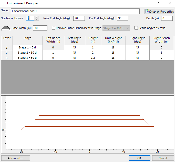
The embankment will be built in three layers. The first is a sand blanket to enable drainage from the wick drains. The other layers are fill for a roadbed. - In the Embankment Designer dialog, set the Number of Layers to 3 and the Base Width to 40 m.
- For Layer 1 you can leave the default values.
- For Layer 2, change the stage to “Stage 2 = 30 d” and set the Left Bench Width and Right Bench Width to 1 m and the Height to 2 m.
- For Layer 3, set the stage to “Stage 3 = 60 d” and the Height to 1.2 m. The dialog should look like this:
- Click OK. You will see crosshairs and will be prompted to pick the near point of the embankment centerline. You can either click in the Plan View or manually enter the coordinates in the bottom right of the screen.
- Enter {0,-50} then press Enter. Now enter {0,50} and press Enter.
- Select Zoom All (or press the F2 function key) and you should now see the embankment in both the Plan View (left) and in the 3D View (right).
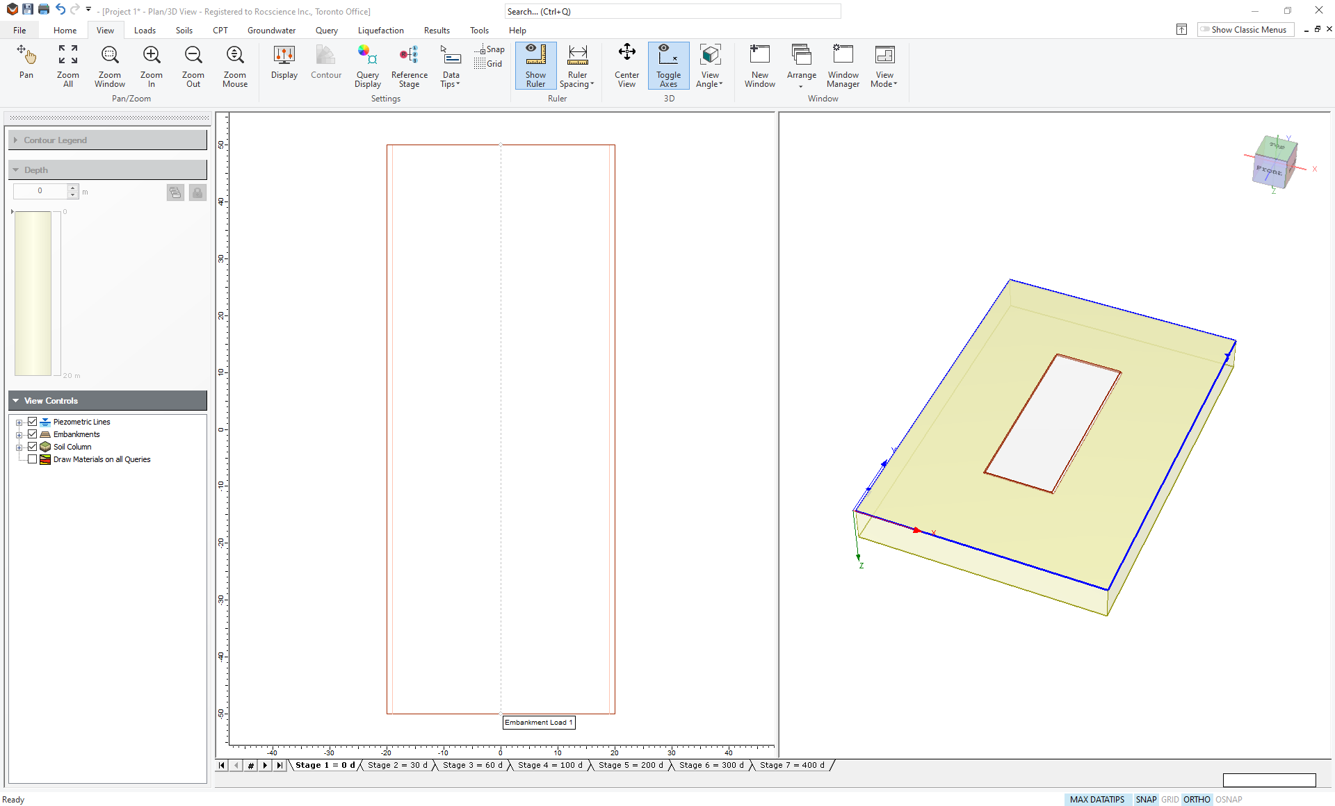
5.0 Soil Layers
The 3D view shows a soil layer with a default thickness of 20 m. It is assumed that rigid bedrock lies below the soil. In this section, we will change the soil properties and layer geometry.
5.1 Soil Properties
- Select Soils > Define Soil Properties

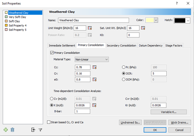
- The first layer shall be named Weathered Clay. Fill in the following soil properties:
- Change unit weight and saturated unit weight to 16 kN/m3 (the non-saturated unit weight is ignored since the water table is at the surface).
- K0 = 0
- Immediate Settlemement is OFF
- Primary Consolidation Settlement is ON with Non-Linear Material Type
- Set Cc = 0.78, Cr = 0.16, e0 = 0.8 and OCR = 5
- For time-dependent consolidation, use the permeability, K and set K = 0.0026 m/d, Kr = 0.0026 m/d
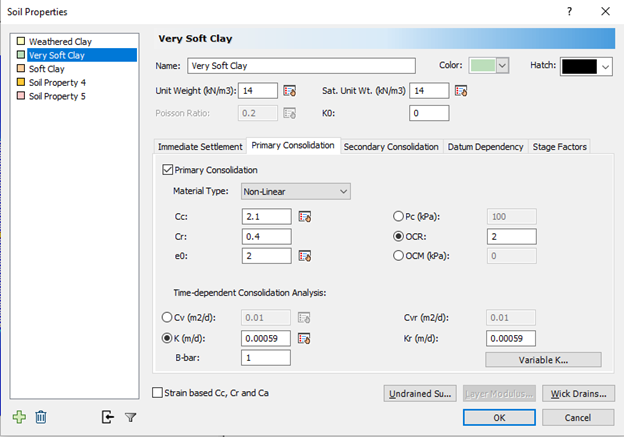
- Click on the tab for Soil Property 2. Change the name to “Very Soft Clay” and fill in the parameters as shown:
- Unit Weight = 14
- Sat. Unit Weight = 14
- K0 = 0
- Primary Consolidation is ON with Non-Linear Material Type
- Cc = 2.1, Cr = 0.4, e0 = 2, OCR = 2
- For time-dependent consolidation, use the permeability K, and set K = 0.00059 m/d, Kr = 0.00059 m/d, and B-bar = 1.
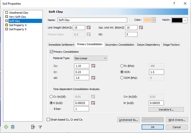
- Now fill in Soil Property 3 as shown:
- Name = Soft Clay
- Unit Weight = 15
- Sat. Unit Weight = 15
- K0 = 0
- Primary Consolidation is ON with Non-Linear Material Type
- Cc = 1.15, Cr = 0.23, e0 = 1.6, OCR = 1.5
- For time-dependent consolidation, use the permeability K, and set K = 0.00025 m/d, Kr = 0.00025 m/d, and B-bar = 1.
- Click OK to close the dialog.
The dialog should look like this:
5.2 Layer Thickness
To change the thickness of the soil layers:
- Select Soils > Layers

Here you can add layers of different materials and change their thickness.
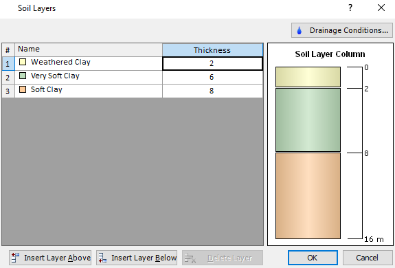
- Click the Insert Layer Below button twice, to create a total of three layers, and enter the thickness as shown.
- Weather Clay = 2
- Very Soft Clay = 6
- Soft Clay = 8
- Click on the Drainage Conditions button, and click the Drained Ground Surface checkbox in the Soil Drainage Conditions dialog.
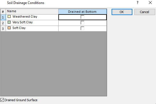
- Click OK to close the dialog.
6.0 Field Point Grid
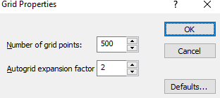
- Select Query > Auto Field (Point Grid)

- Enter Number of grid points = 500, and Expansion factor = 2.
- Click OK.
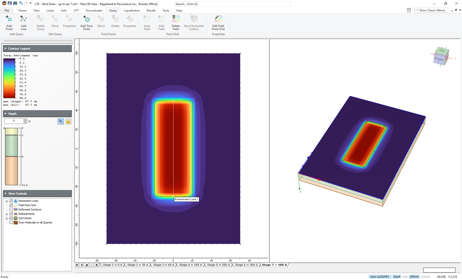
A grid will be generated and stresses and settlements will be automatically computed throughout the 3-dimensional volume. By default, contours for Total Settlement will be shown (you can change this using the drop down menu in the Results tab). This will take a little time, depending on the speed of your computer. Click through the stages to observe settlement with time. Your model for Stage 7 (400 days) should now look like this:
7.0 Results Visualization
7.1 Query Point
You can see from the contour plot that the maximum settlement after 400 days is 87.7 cm. What we now need to determine is whether or not the soil has finished consolidating. To do this we will use a Query Point to look at the excess pore pressures at depth.
- Select Query > Add Point

You will see the Query Point dialog as shown: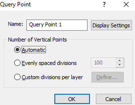
- Leave the default choice of Automatic. This will generate subdivisions such that the discretization is denser near the ground surface where the high-stress gradients are likely to be.
- Click OK and the cursor will become a cross-hairs in the Plan View. You now need to specify the location of the Query Point. Enter the coordinates 0,0 in the bottom right of the screen and hit Enter to place the Query Point at the centre of the embankment.
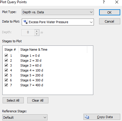
- Now right-click on the query point and select Graph Query.
- For Plot Type choose Depth vs. Data.
- For Data to Plot choose Excess Pore Water Pressure.
- For Stages to Plot choose Select All.
- Click OK to draw the graph. The graph should look like this:
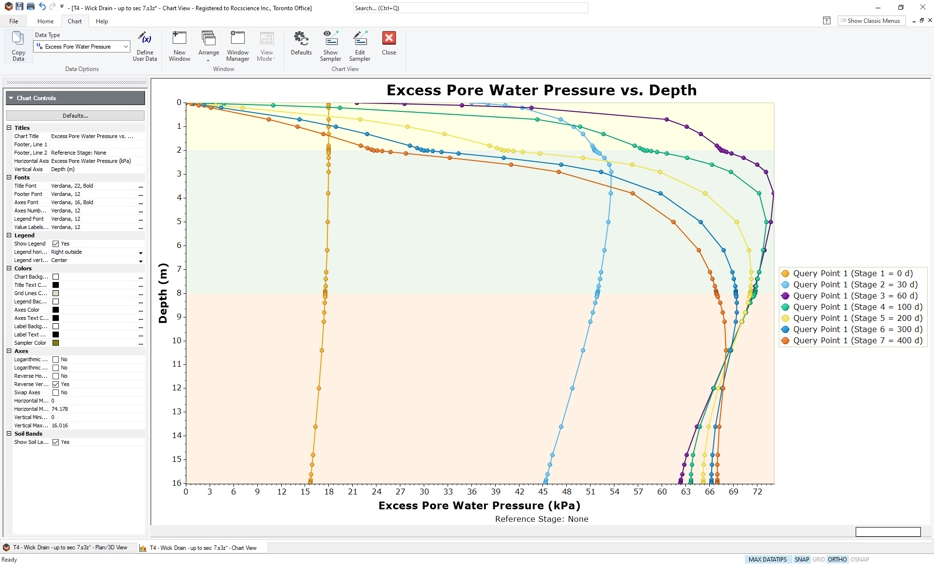
You can see that at 400 days, excess pore pressure has not dissipated from the lower layer, indicating that the embankment has not finished settling. To speed up the settlement, we will add an array of wick drains.
8.0 Wick Drains
Wick drains or prefabricated vertical drains (PVDs) can be driven into the soil at regular spacings to speed up consolidation. Pore water flows horizontally towards the drains and then water flows freely up the drains to the surface. This speeds up consolidation in two ways: i) horizontal permeability is usually higher than vertical permeability so horizontal flow is faster, ii) the lengths of the flow paths are significantly shortened. In this tutorial, we will show how wick drains can be used to speed up consolidation under the embankment load.
8.1 Horizontal Flow Properties
Before we install wick drains, we need to specify the horizontal flow behaviour in the different materials.
- Click the tab at the bottom to go back to the Plan/3D View.
- Select Define Soil Properties from the Soils tab.
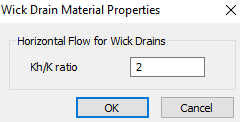
- For the Weathered Clay, click on the Wick Drains button. We will assume that the material is twice as permeable in the horizontal direction as it is in the vertical so set the ratio of horizontal to vertical permeability to 2 as shown.
- Click OK.
- Repeat for the other 2 materials so that all material layers have a horizontal permeability that is double the vertical.
- Close the Soil Properties dialog.
8.2 Wick Drain Properties
To add an array of wick drains:
- Select Groundwater > Add Wick Drain

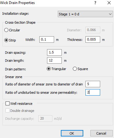
- Enter the following wick drain properties:
- Installation Stage = Stage 1 = 0 d
- Cross-Section Shape = Strip, Width = 0.1 m, Thickness = 0.005 m
- Draining space = 1.5 m
- Drain length = 12 m
- Drain pattern = Triangular
- Smear zone
- Ratio of diameter of smear zone to diameter of drain = 5
- Ratio of undisturbed to smear zone permeability = 2
- The length of the drains is only 12 m, so they do not extend to the bottom of the Soft Clay layer.
- We are assuming there is a smear zone. The smear zone results from the driving of the drains into the soil. This generally causes disturbance close to the hole and a decreased permeability.
- We have selected strip (band) drains, with an effective 10 cm width and 5 mm thickness. An equivalent circular drain would have diameter given by d = 2(b+t)/pi = 0.067 meters.
- Click OK to close the dialog.
- You must now enter the coordinates of the wick drain region in the Plan View. We want the wick drain region to completely cover the embankment. You can use the mouse to graphically enter the coordinates, or enter the following points in the prompt line:
{22,52}, {-22,52}, {-22,-52}, {22,-52}, "c" (to close the region)
TIP: You can display the drains in the 3D View by clicking on the Display Options button, selecting the 3D View tab and selecting the Show Wick Drains checkbox.
9.0 Results
If your model did not already Auto Compute, choose Compute from the Results menu to re-compute the contours. Your model should look like this for Stage 7:
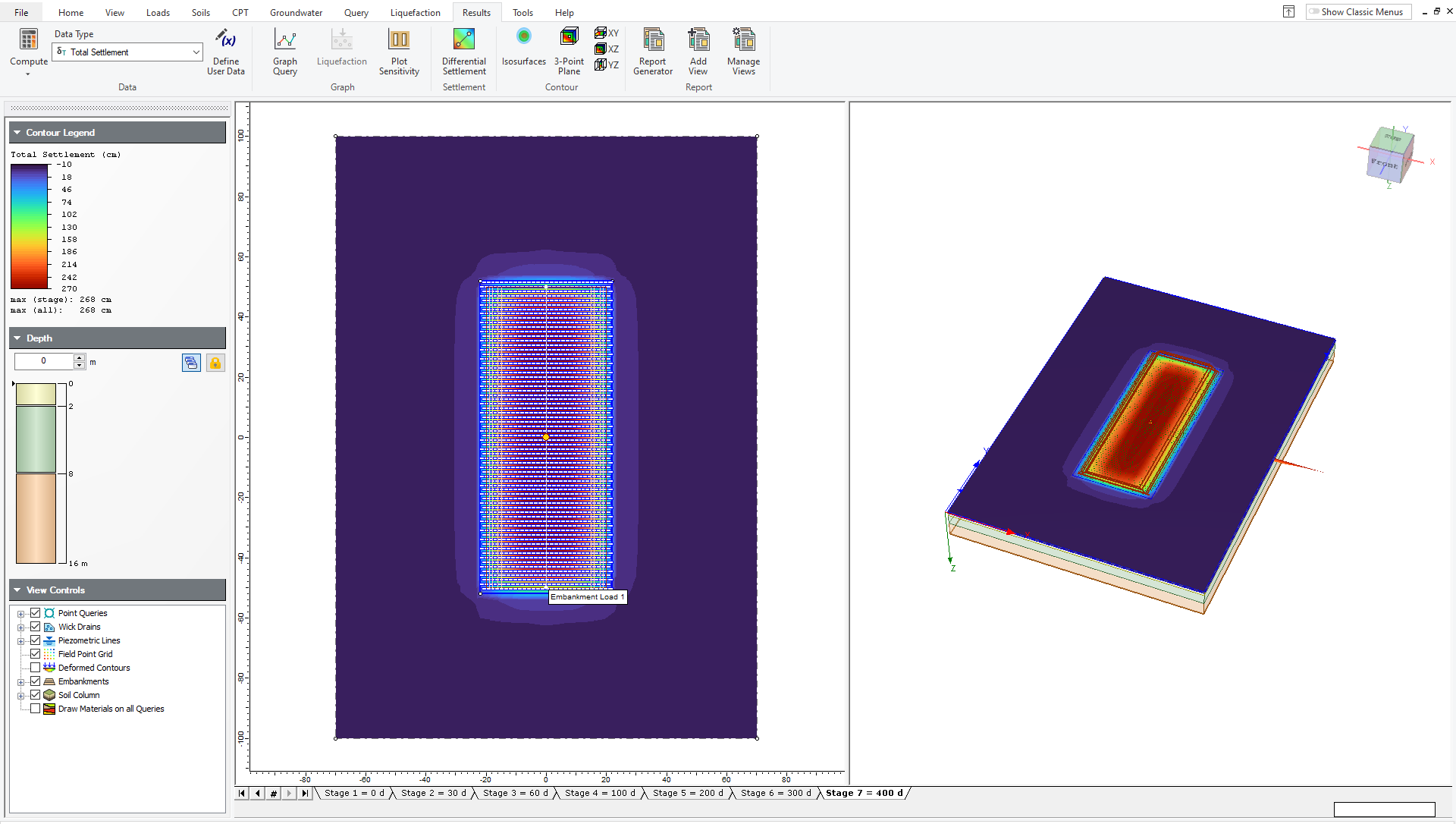
You can see that the maximum settlement is now 268 cm.
Go back to the graph of excess pore pressure for the query point and it should look like this:
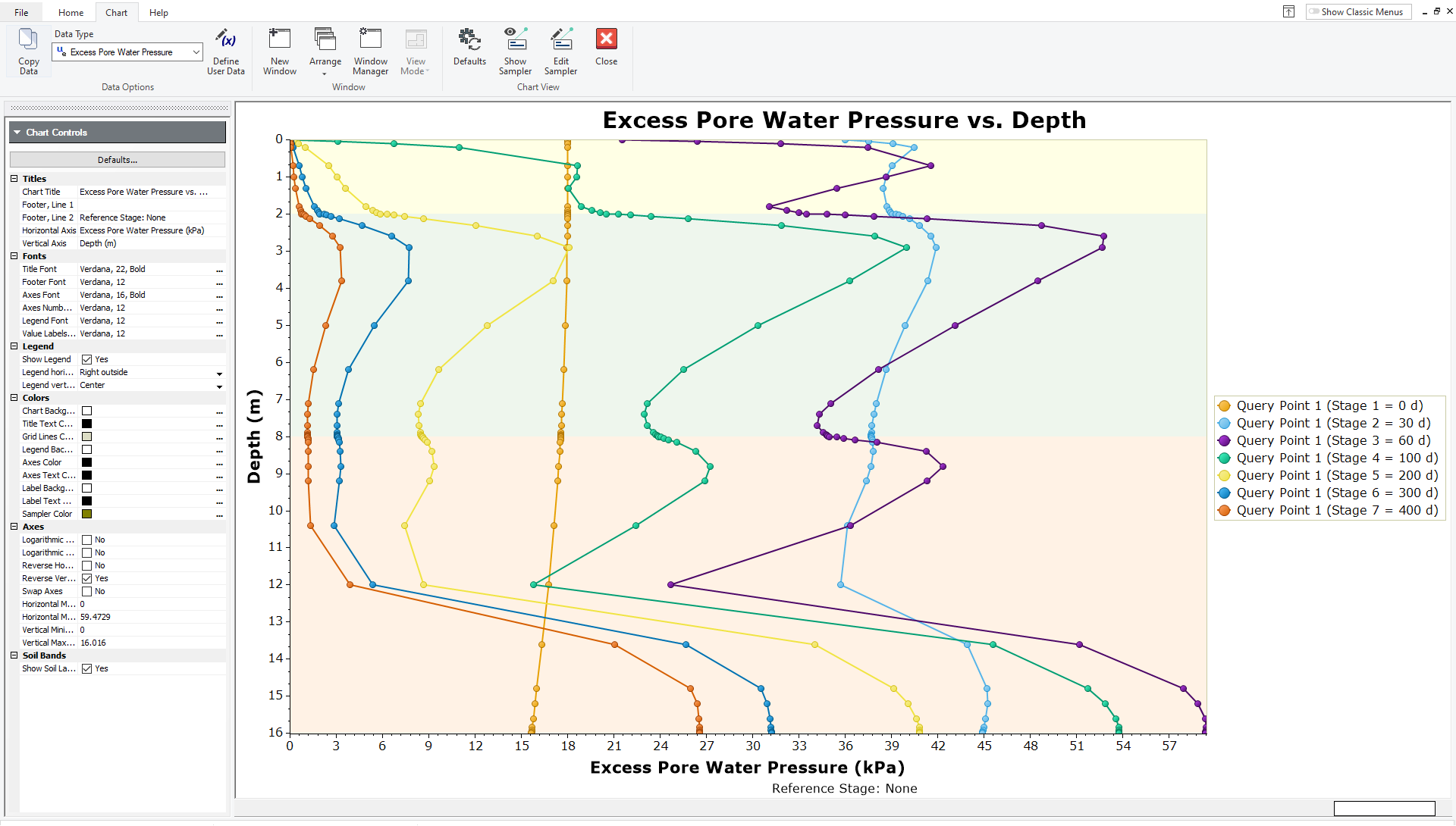
Here you can see that at 400 days, the excess pore pressure is close to zero throughout the model, except in the bottom 4 meters where the wick drains do not penetrate. It is likely therefore that the soil has mostly finished consolidating.
To check this:
- Close this graph and draw another graph for the query point by right-clicking on the point in the 2D view and selecting Graph Query.
- Choose Plot Type: Data vs. Stage Time and choose Total Settlement at Depth: 0.
In the Sidebar under Axes, change the horizontal and vertical values to the following:
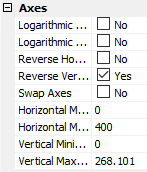
Your plot should look like this:
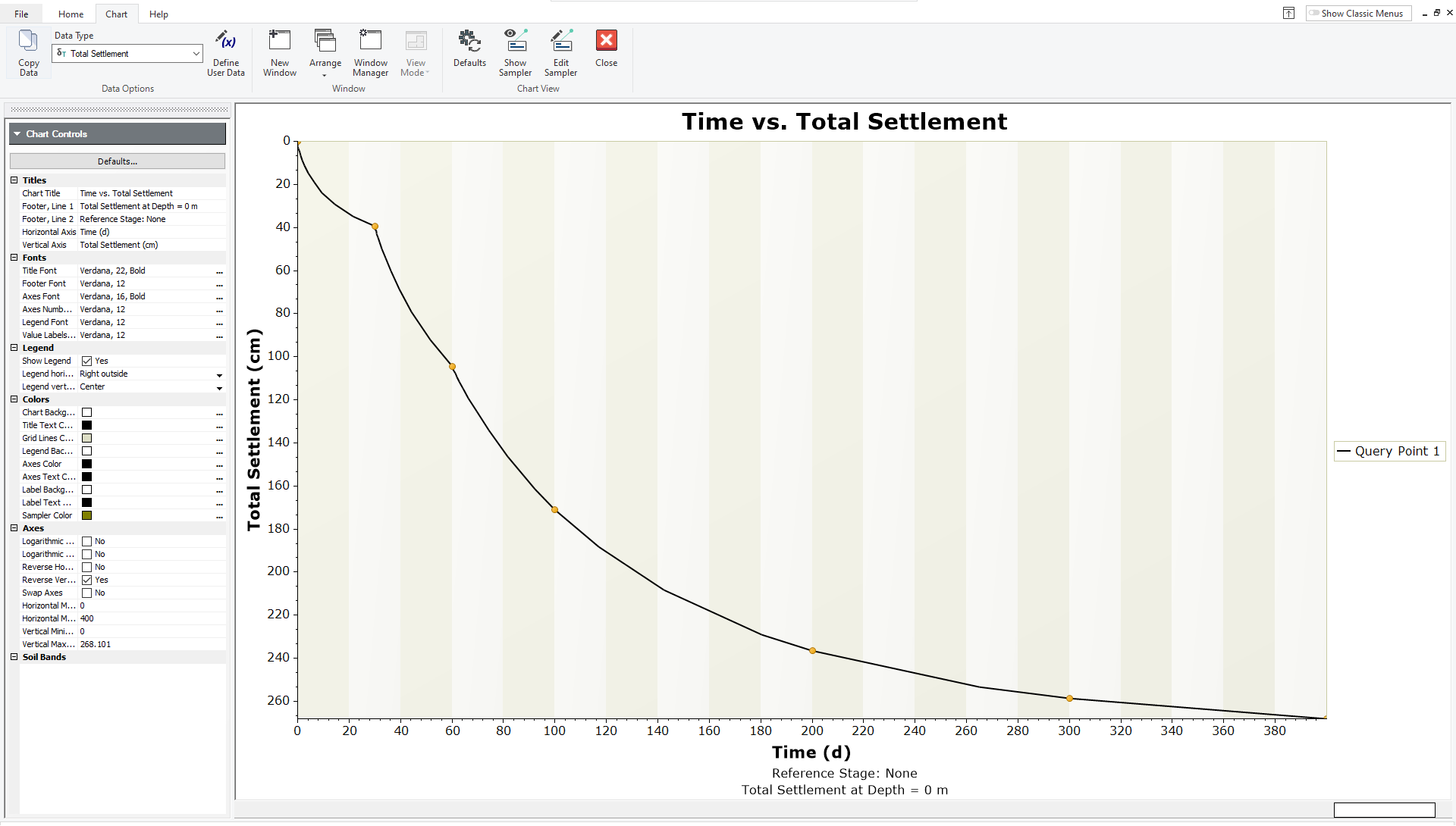
Here you can see that the rate of settlement is decreasing with time and that the graph is nearly flat at 400 days, indicating that there should not be much more settlement.
This concludes the Wick Drain tutorial; you may now exit the Settle3 program.