22 - Section Creator
1.0 Introduction
In Settle3, there are three ways in which you can define the soil profile layout - horizontal, non-horizontal, and extruded section layer. For the extruded section layer, you can use the Section Creator which allows you to create a 2D soil profile with boreholes, which is then extruded in the perpendicular direction of the section defined in the 2D plan view. In this tutorial, we will show how to use this feature, along with what you get after you have completed creating your soil profile in the Section Creator.
Topics Covered in this Tutorial:
- Extruded section layer
- Section creator
- Boreholes
Finished file:
The initial file and the finished file can be found in the tutorial folder Tutorial 22 - Section creator. All tutorial files installed with Settle3 can be accessed by selecting File > Recent Folders > Tutorials Folder from the Settle3 main menu.
1.1 Starting file
The starting file can be found in the tutorial folder File > Recent Folders > Tutorials Folder. This file contains soil properties and boreholes. We will use the boreholes to create a 2D section soil profile with the Section Creator feature.
- Select File > Recent Folders > Tutorials Folder and open Tutorial 22 - Section creator_initial.s3z.
2.0 Model
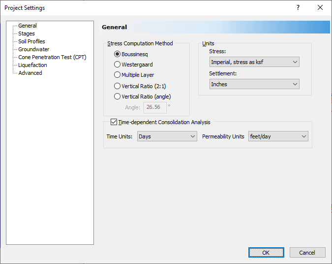
2.1 PROJECT SETTINGS
- Select Home > Project Settings
 to open the Project Settings dialog.
 - In the General tab, make sure the Time-Dependent analysis option is selected.
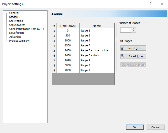
- Select Stages. Make sure you see 9 stages with the time shown below.
- In the Soil Profiles tab, select Extruded section layers option.
- Select the Groundwater tab. Select the Groundwater Analysis and keep the default values.
- Click OK to exit the dialog.
| # | Time (days) | Name |
| 1 | 0 | Stage 1 |
| 2 | 500 | Stage 2 |
| 3 | 1000 | Stage3 |
| 4 | 1500 | Stage 4 |
| 5 | 1600 | Stage 5 - install side |
| 6 | 1630 | Stage 6 - slab |
| 7 | 1690 | Stage 7 |
| 8 | 5000 | Stage 8 |
| 9 | 7000 | Stage 9 |
2.2 SOIL PROPERTIES
The initial starting file already has set up the soil properties defined. You can check the soil properties set up in the model using the Soil Properties dialog.
- Select Soils > Define Soil Properties

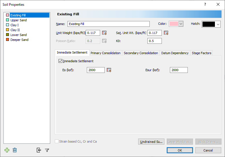
- You should see 6 different types of soil. Click OK to exit the dialog.
2.3 BOREHOLES
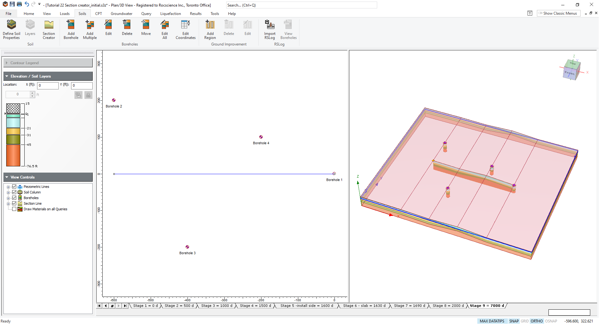
- Select Soils > Edit All Boreholes

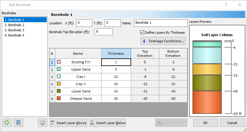
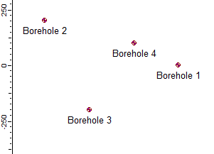
You will see there are four existing boreholes defined in the initial tutorial file. The boreholes are also shown in the Plan View.
3.0 Section Creator
Next, we use the Section Creator to create a soil profile with the defined boreholes.
- Select Soils > Section creator

- You'll be prompted with Enter vertex on the command prompt shown at the bottom right of the program.

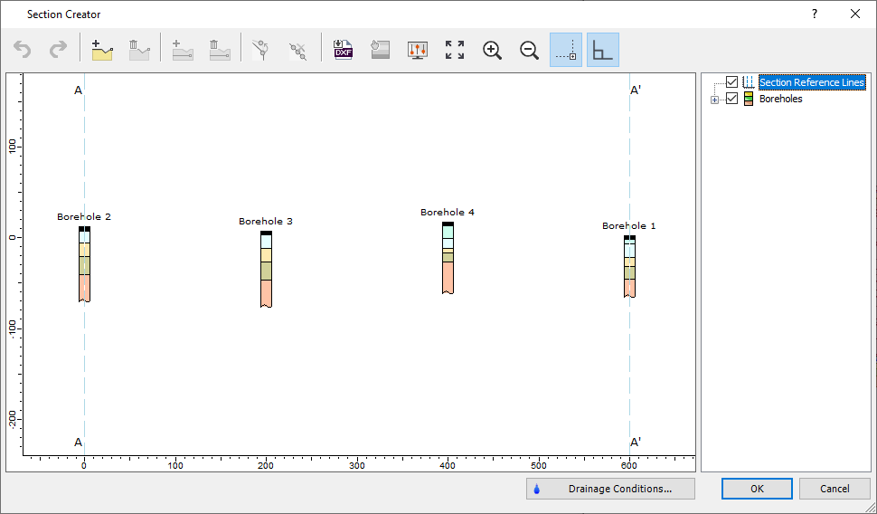
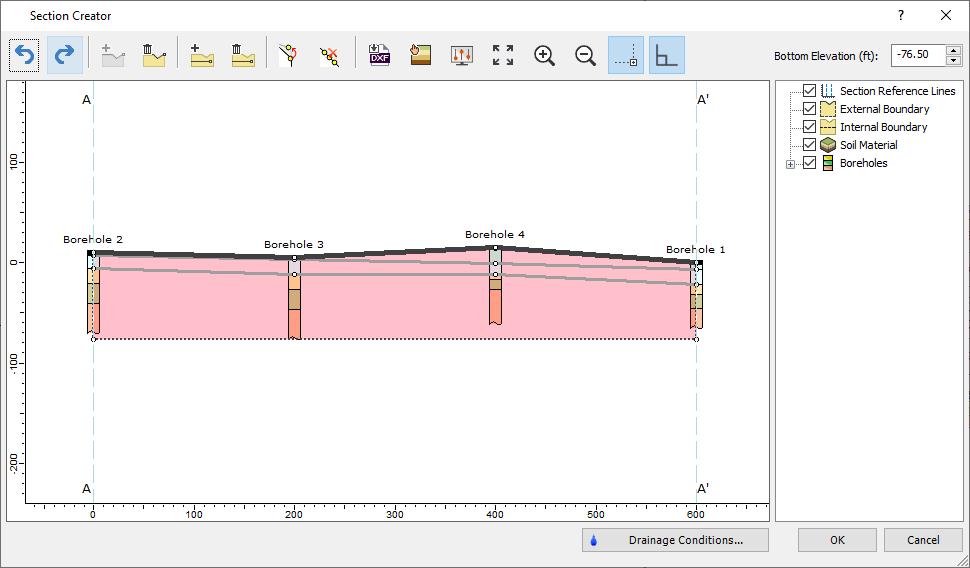
- Enter the following coordinates: {-600, 0} for first point, then {0, 0} for second point. Press ENTER when done. After you define where you want to define your section, you will see the section creator dialog with boreholes as shown below:
3.1 GROUND SURFACE LAYER
We will first create the ground surface with the defined boreholes.
- Click Draw Ground Surface

- You will be able to snap along the top of the boreholes. Select the top points of each boreholes as shown below.
- Right click and select Done after you've selected all the vertices.
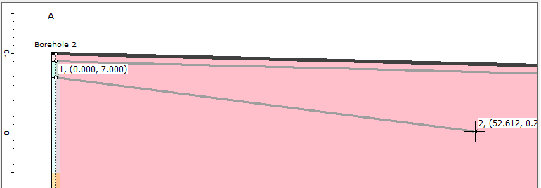
Tip: If you're finding it hard to select the top surface of boreholes, you can zoom in / zoom out on each boreholes with scrolls or built in zoom/in out feature for each boreholes . Below is an example of utilizing zoom in feature to select the top surface.
3.2 INTERNAL BOUNDARIES
Now we will draw internal boundaries to connect between the boreholes.
- Click Draw Internal Boundary

- Zoom in to each boreholes and select the layer underneath the top surface (1m fill layer) as shown below.
- Repeat this process for three other boreholes.
TIP: In case you have accidentally selected the wrong location, you can undo the selection by Right click > undo.
You should see the fill layer formed right underneath the ground surface layer.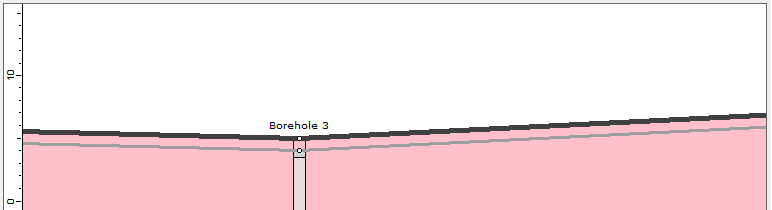
- Now we will repeat this process for other layers. Select the layer underneath the fill layer as shown below and continue connecting this line to other boreholes with this layer.
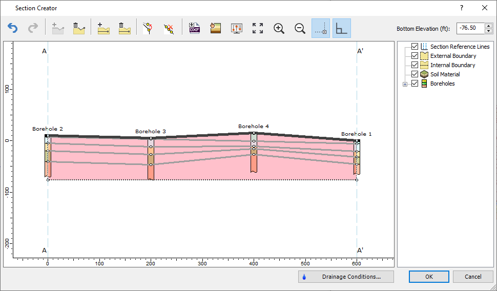
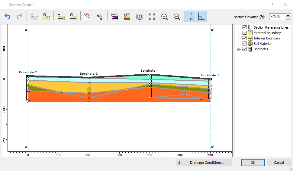
- After drawing all internal boundaries by connecting the soil deposit depths from boreholes, note that the bottom elevation is already defined as bottom of the borehole. You can modify to different bottom elevation but for this tutorial, we'll keep it at bottom elevation of borehole. The section with internal boundaries should look at the following:
Your soil profile should look as the following after three-layer boundaries are added:
3.3 ASSIGN MATERIALS
We can assign materials for each layer boundaries drawn.
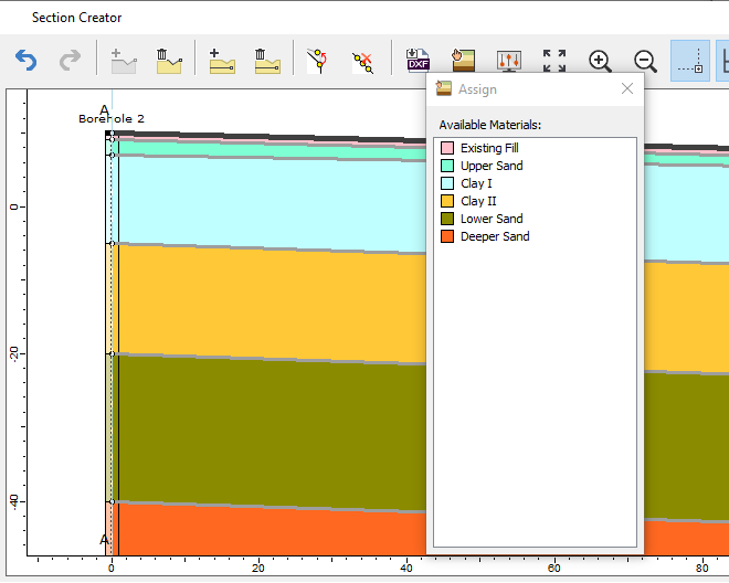
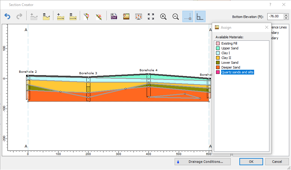
- Click Assign Materials

- You will be able to see list of material properties available to assign. We will assign each layers with the order shown in available materials: Existing Fill, Upper Sand, Clay I, Clay II, Lower Sand, and Deeper Sand.
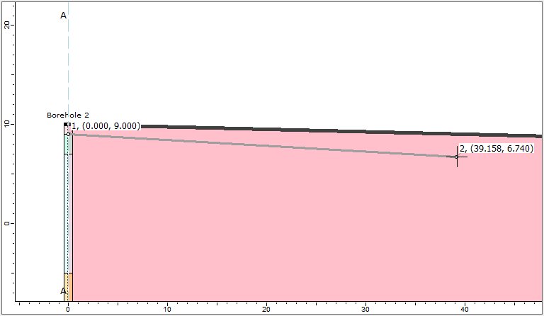
- Zoom into the left borehole (Borehole 2) and assign each layer section with corresponding material as shown below:
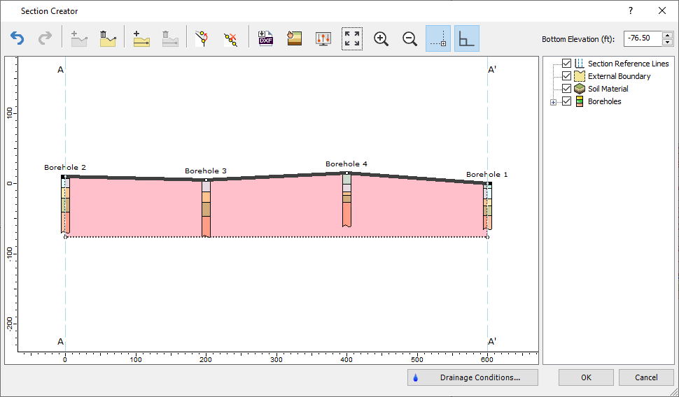
After assigning the material properties to each layer, your overall section profile should look as the following: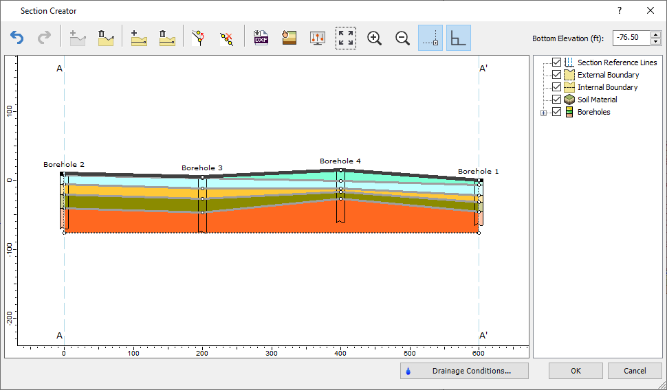
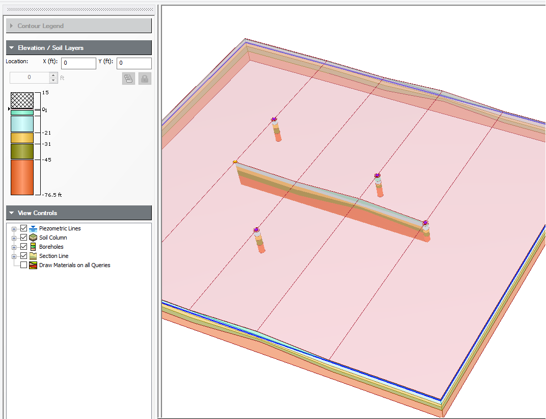
- Click OK to exit the dialog and you will see the 3D soil model created with the section creator as shown below.
You can also see the section you have created in 3D viewer when Section Line is selected in the view controls as shown below.
4.0 Add Load
4.1 ADD EMBANKMENT LOAD
Now we will apply embankment load to the created section.
- Select Loads > Loads by Zone
 to open the Embankment Cross Section Designer.
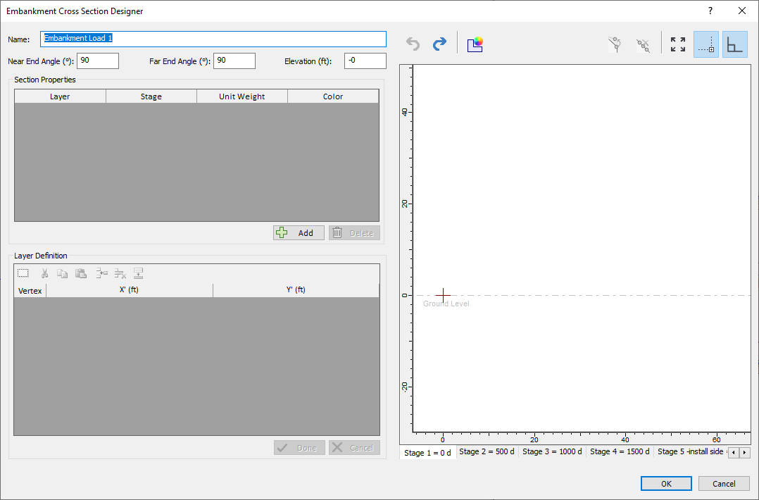
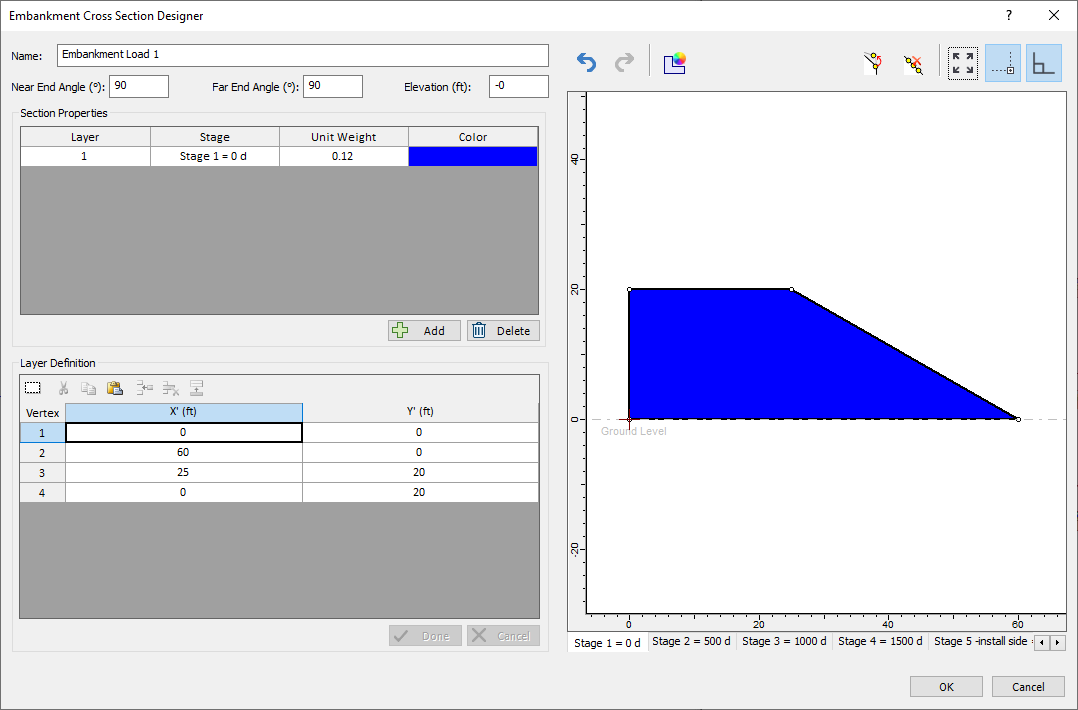
- Click Add and enter a Unit Weight of 0.12 at Stage 1.
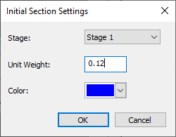
- Click OK.
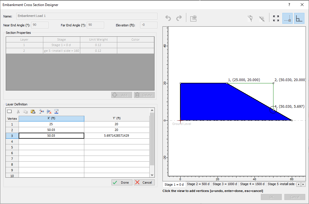
- Enter the following coordinates to the first embankment:
- Click Done and the embankment should look as the following:
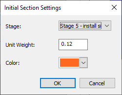
- Next, we will apply staged embankment installation. Click Add again. Enter the Unit weight of 0.12 and select stage 5 for installing the side extension embankment.
- This time, we will be extending the right portion of the embankment with a width of 25ft. Select two vertices and connect the last point to the first embankment as shown below:
- Click Done and you should see the extended embankment shown below.
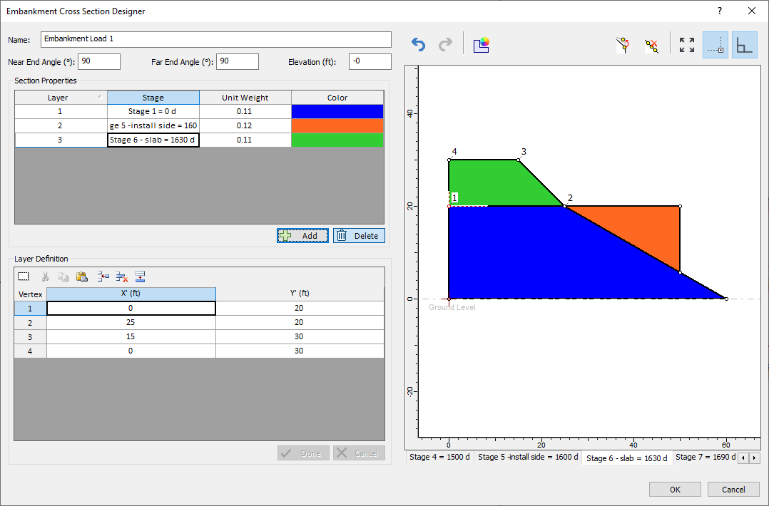
- We will lastly apply the top extension of the embankment on top. Click Add.
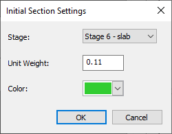
- This installation will be applied 30 days prior to the side embankment (Stage 6). Enter the Unit weight of 0.11. Select different color and click OK.
- Enter the following coordinates and click Done.
- Before we click OK, we have to assign the elevation of the embankment. Enter 16 ft for Elevation (ft).
- Click OK.
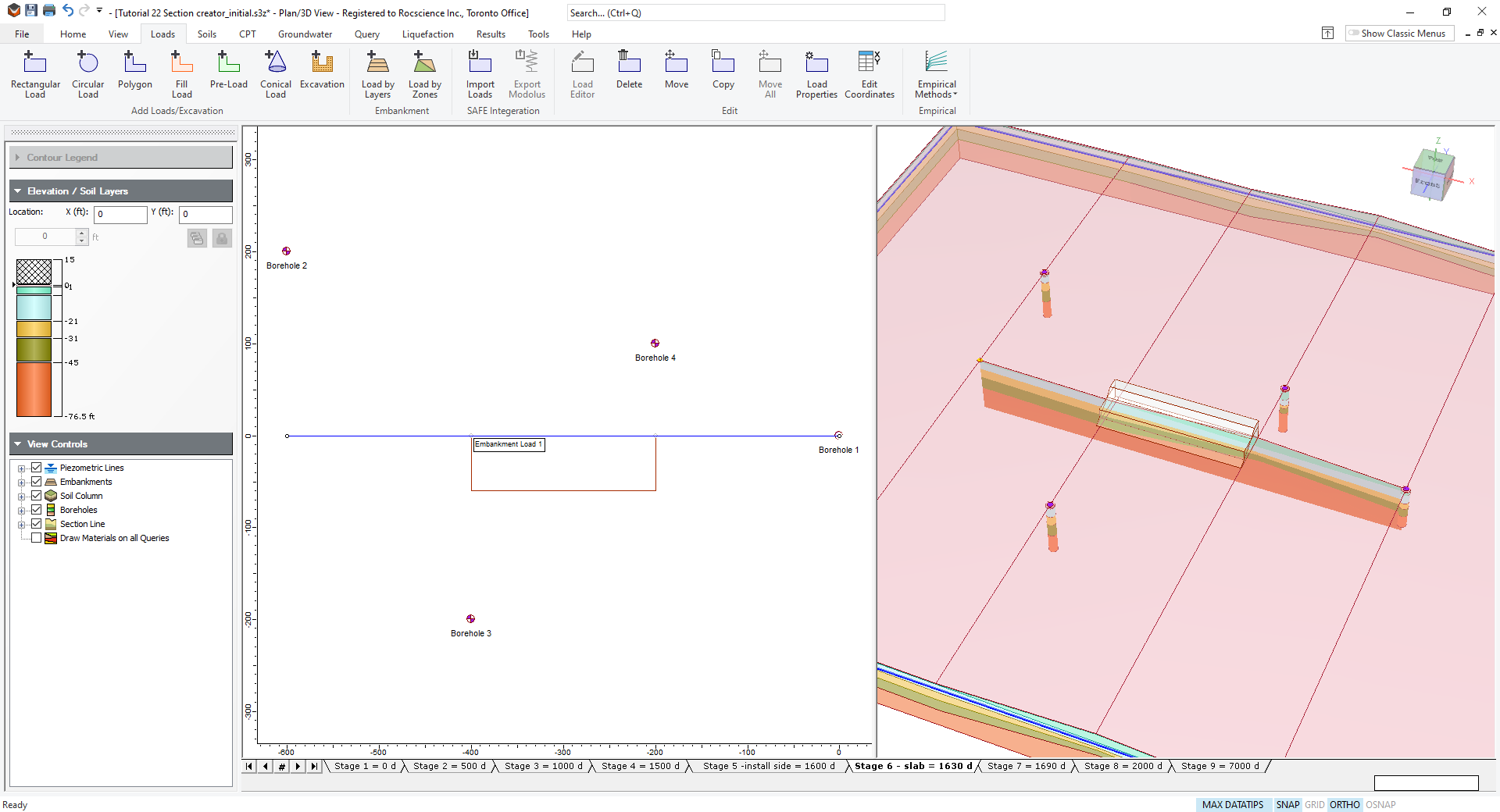
- Now we will apply the embankment we have created to the model. Enter {-400, 0} for first point and enter {-200, 0} for second point to apply embankment load to the model.
| X | Y |
| 0 | 0 |
| 60 | 0 |
| 25 | 20 |
| 0 | 20 |
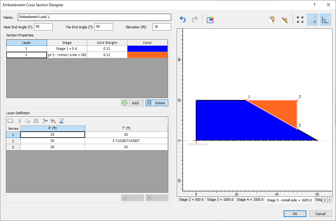
| X | Y |
| 0 | 20 |
| 25 | 20 |
| 15 | 30 |
| 0 | 30 |
You should see the following installation of the embankment shown below after stage 6.
You will see the embankment as shown below.
4.2 ADD POLYGONAL LOAD
Now we will add a rectangular load on top of the embankment using the polygonal load option.
- Select Loads > Polygon

- Enter the following coordinates for the vertices: {-400 -30}, {-200, -30}, {-200, -10}, {-400,- 10}. Press ENTER or select Done.
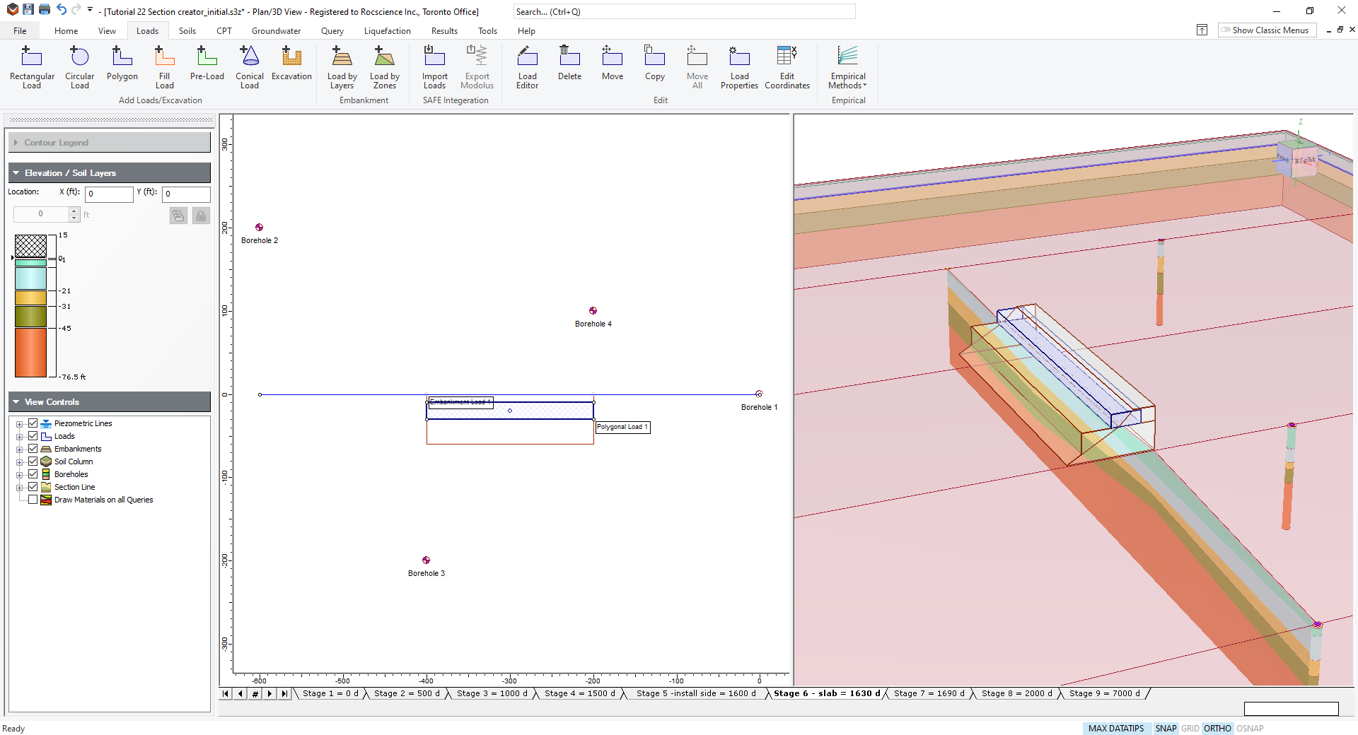
- Enter Pressure as 0.11 ksf and a Bottom Elevation of 36 ft. The Installation Stage should be at Stage 6.
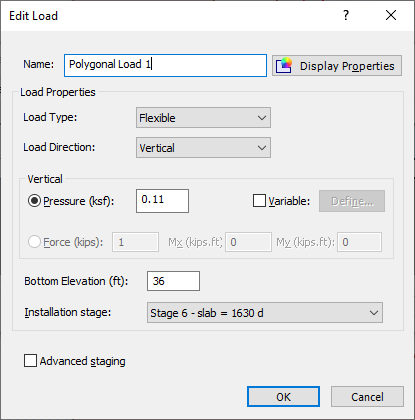
- Click OK. You should see the embankment with slab load as shown below.
5.0 Results
5.1 QUERY LINE
Add a query line underneath the embankment to see the settlement results.
- Select Query > Add Line

- Click OK when the dialog pops up (keep default value) and enter the coordinates {-400 -20} and {-200, -20}.
- We will add another query line along the width of the embankment at the center. Select Add query line again and enter the following coordinates: {-300, -40}, {-300, 20}.
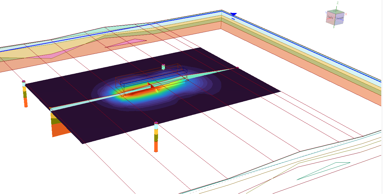
You should see the following contour settlement result as shown below underneath the load.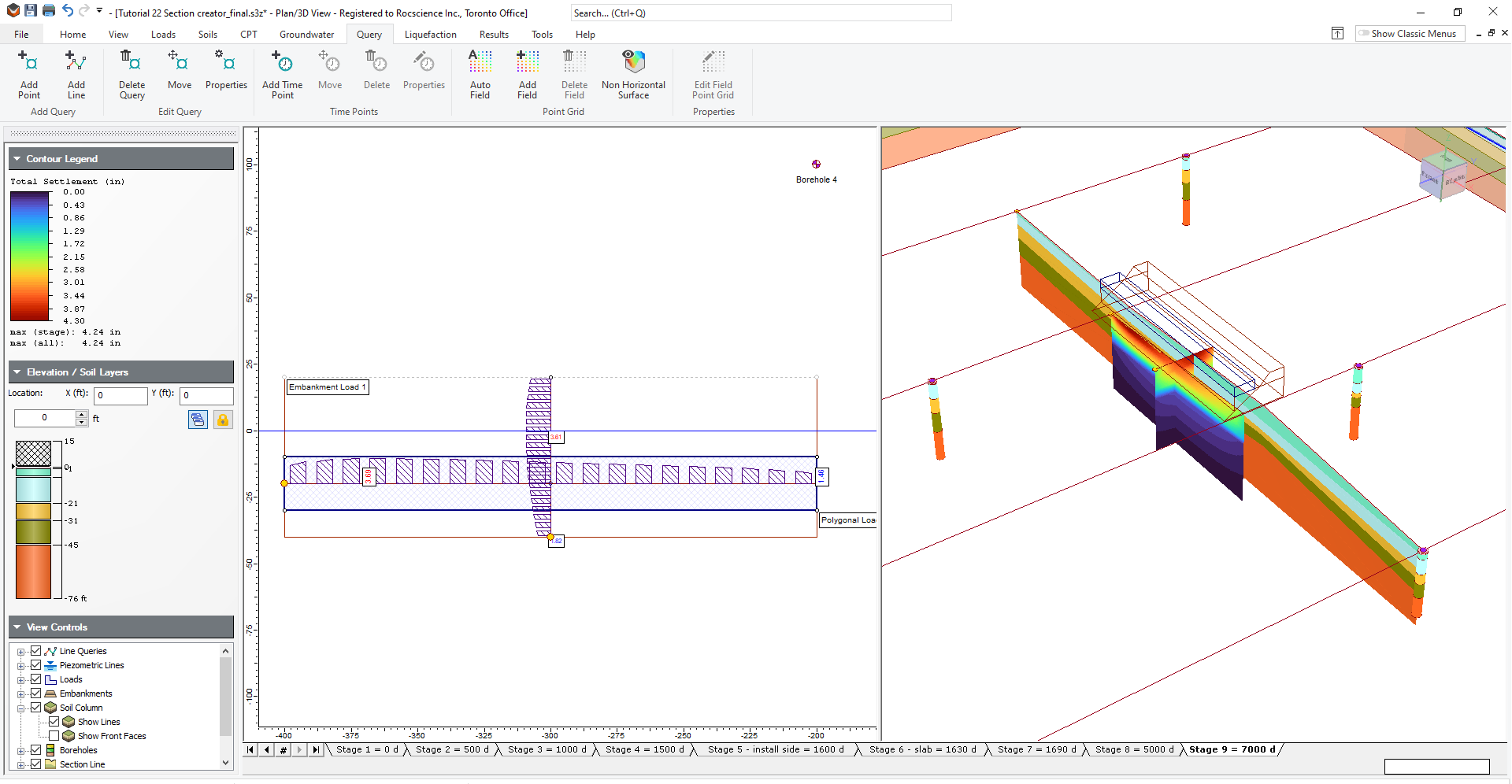
- You can also see the field grid contour of settlement underneath the embankment load by selecting Query > Auto Field Point Grid

- Keep the default values and click OK.
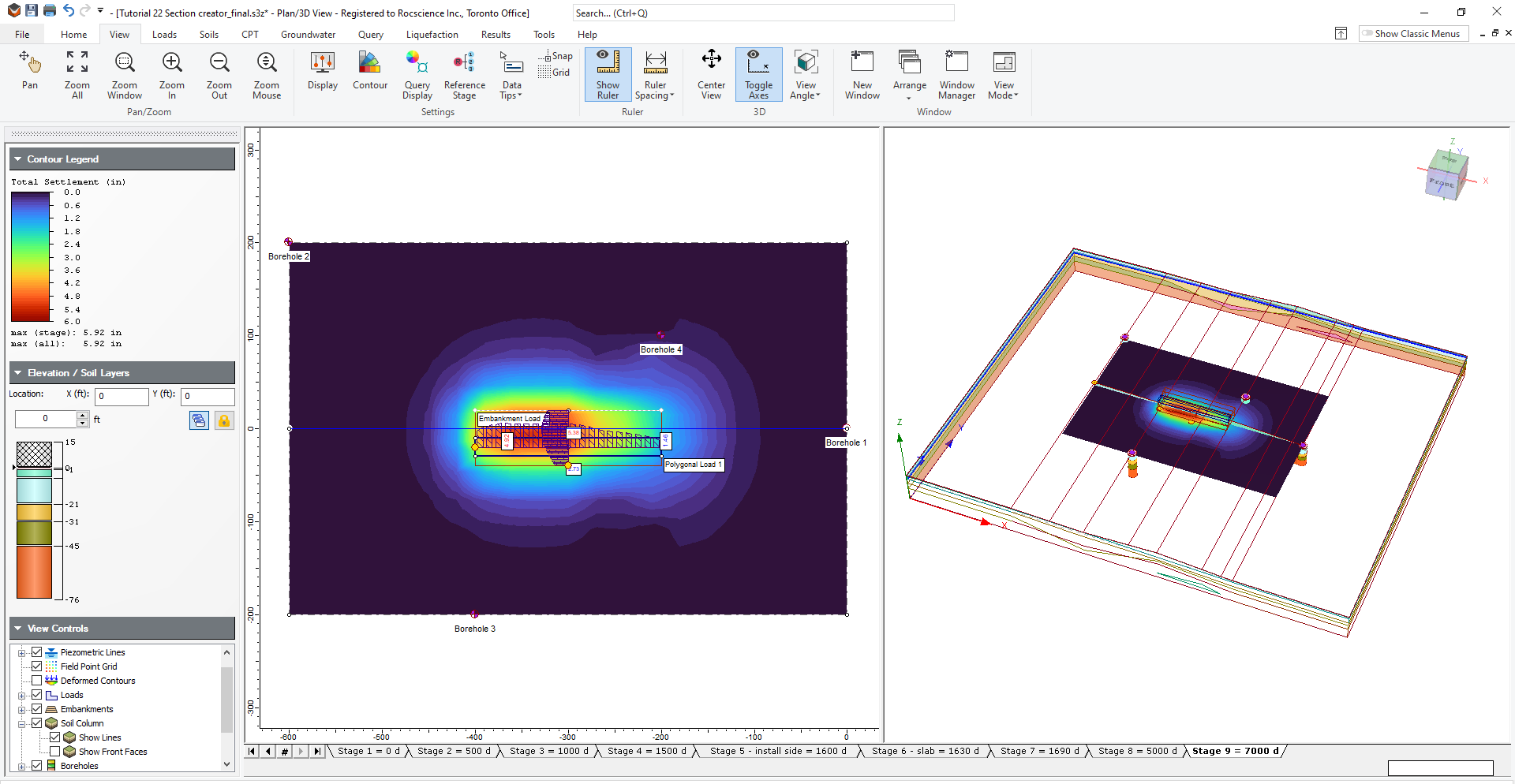
You should be able to see the contour of settlement as shown below:

As shown above, the contour settlement shows greater settlement along the region where the soil profile is thinner than the right side of the embankment where the soil profile is thicker. Also, note that the load is applied at constant elevation along the width of the embankment. The field grid point shows distributed settlement that corresponds to the soil profile created with the section creator.
We recommend you to try out different types of analysis using this model such as adding additional load for immediate settlement, or ground improvement and run primary consolidation analysis.
This feature allows you to create a variety range of soil profiles with flexibility of defining soil layout along the section line A-A'. Section creator option provides many other features including import *.dxf, extended material layers outside the section line A-A' etc. Be sure to check out the Section creator help page for more information.
6.0 Additional Exercise
As an additional exercise, we'll use the improved section creator to model a 2D soil profile with sink holes and non-horizontal soil layer in the section creator.
Before we modify the section creator, we’ll be assigning a new soil material type to the new section.
6.1 SOIL PROPERTIES
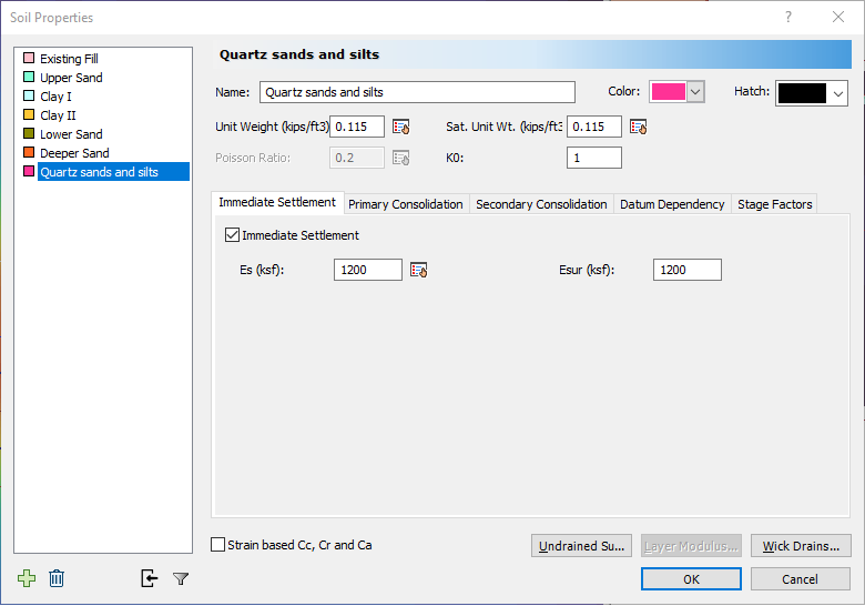
- Select Soils > Define Soil Properties
- Create a new layer by selecting the plus icon and name it Quartz sands and silts.
- Keep the Unit Weight and Saturated Unit Weight to 0.115 (kips/ft3).
- Enable Immediate settlement with Es and Esur values of 1200 ksf.
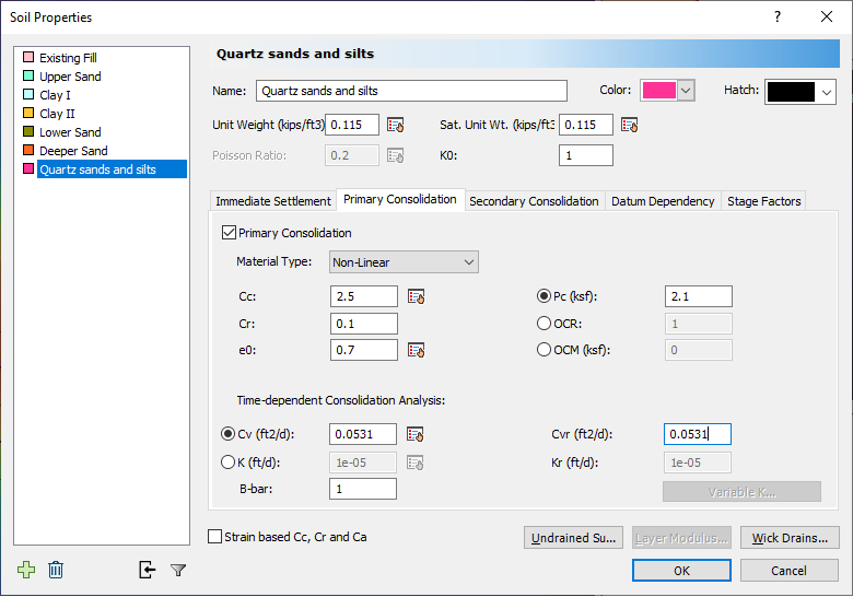
- Go to the Primary consolidation tab. Select the Non-linear method and enter the following parameter values:
- Cc = 2.5,
- Cr = 0.1,
- e0 = 0.7, Pc = 2.1.
- Cv & Cvr = 0.0531 ft2/d
- B-bar = 1.
Now we’ll be assigning this new material to the 2D soil profile in section creator.
6.2 SECTION CREATOR
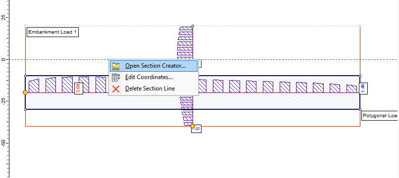
- Right click on the section creator and select Open Section Creator. We’ll be modifying the soil profile from the section creator.
- Right click on third vertex of borehole 3 and move it down to the bottom layer as shown below.
Before: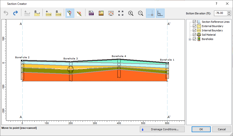
After: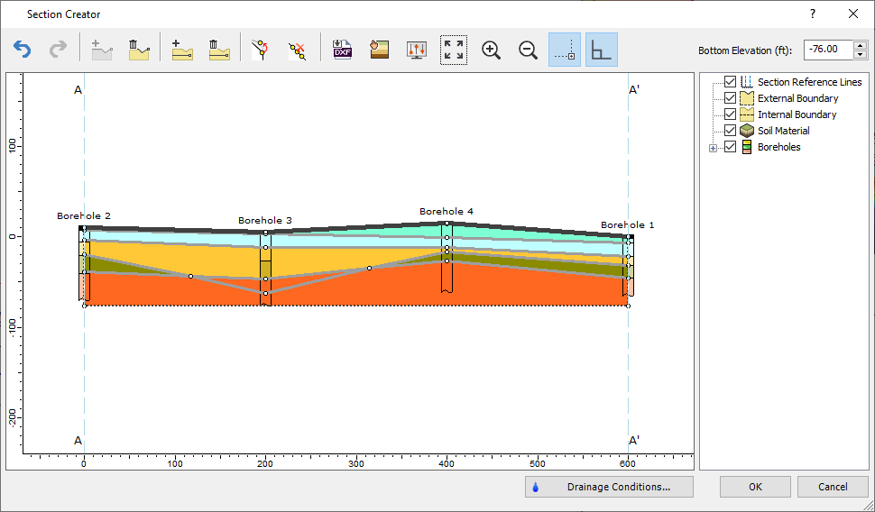
- The modified vertex coordinate for this specific tutorial is at (200, -62.7). You can right click on the internal boundary line and re-enter the coordinates to match with the tutorial example.
Now we’ll add another discontinuous soil layer which starts at the end of Borehole 4.
6.3 INTERNAL BOUNDARIES
- Click Draw internal boundary
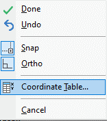
- Select the starting point at the end of the Borehole 4. While the line is being drawn, right click and select Coordinate Table as shown below.
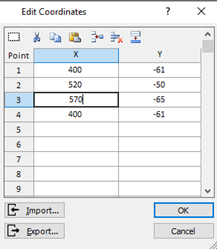
- Enter the following coordinates.
| X | Y |
| 400 | -61 |
| 520 | -50 |
| 570 | -65 |
| 400 | -61 |
After modifying the layers, you’ll see that now we have a two discontinuous soil layers within the 2D soil model profile as shown below:
6.4 MATERIAL ASSIGNMENT
- Click Assign materials

- We’ll be assigning Quartz sands and silts to these modified layers. The following below shows the assigned soil layer as shown below:
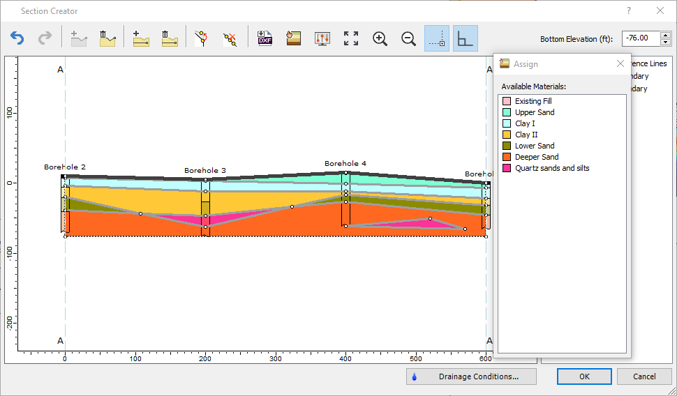
- Click OK. Then, you’ll see the updated soil profile with new settlement analysis result as shown in section 6.5.
6.5 RESULTS
This is a close-up view of the modified 2D soil profile with discontinuous soil layer addition.
This concludes the tutorial 22 – section creator.