19 - Embankment Cross Section Designer
This tutorial introduces the Cross Section feature in the Embankment Designer dialog in Settle3 that allows users to define layers within the cross section of an embankment. This will enable the user to build the embankment in any predefined layering which simulates road, dam construction or extension of old embankments.
Topics Covered in this Tutorial:
- Embankment Cross Section Designer
- Advanced Embankment Staging
- Non-Horizontal Layering
- Boreholes
Finished Product:
The finished product of this tutorial can be found in the embankment_final.s3z file. All tutorial files installed with Settle3 can be accessed by selecting File > Recent Folders > Tutorials Folder from the Settle3 main menu.
1.0 Introduction
The Embankment Cross Section Designer feature is closely related to the embankment designer feature which was first introduced in Tutorial 8 which can be found here on the Settle3 tutorials page. To guide users through this new feature, we will model the extension of a road embankment by considering three separate stages. The first stage will represent the existing condition of the road embankment, the second stage will aim to extend the embankment to make the existing road wider, and the third stage will raise the embankment to the appropriate height.
In addition to the soil properties of the subsurface materials and embankment fills, three boreholes will be used to define non-horizontal soil layering. We will now begin by defining the project settings.
2.0 Model
If you have not already done so, run the Settle3 program by double-clicking the Settle3 icon in your installation folder or by selecting Programs > Rocscience > Settle3 in the Windows Start menu.
When the program starts, a default model is automatically created.
2.1 Project Settings
- Select Home > Project Settings

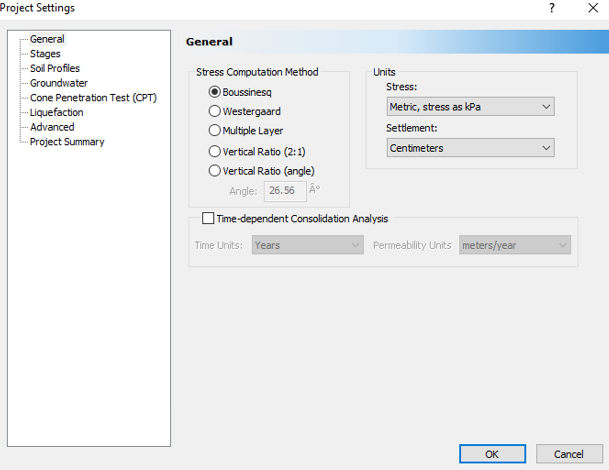
- In the General tab, please select the following options:
- Stress Computation Method = Boussinesq
- Units
- Stress = Metric, stress as kPa
- Settlement = Centimeters
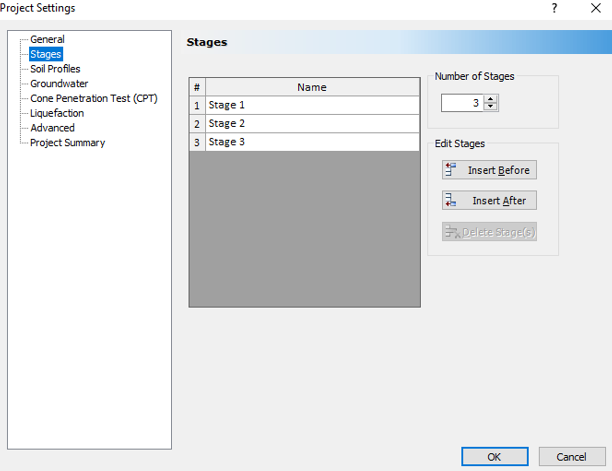
- Select the Stages tab. Increase the Number of Stages to 3. Since we are only interested in the immediate settlement, there is no need to check the time-dependent calculation box and no need to add time durations for the stages.
- Since our model requires non-horizontal layering, select the Soils Profile tab and change the Layer Options to Non-Horizontal Layers to allow more than one borehole to be applied.
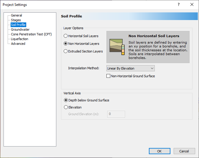
- You can choose the Interpolation Method for the extension of layers between the boreholes. For the purpose of this tutorial, we will keep the default option of Linear by Elevation.
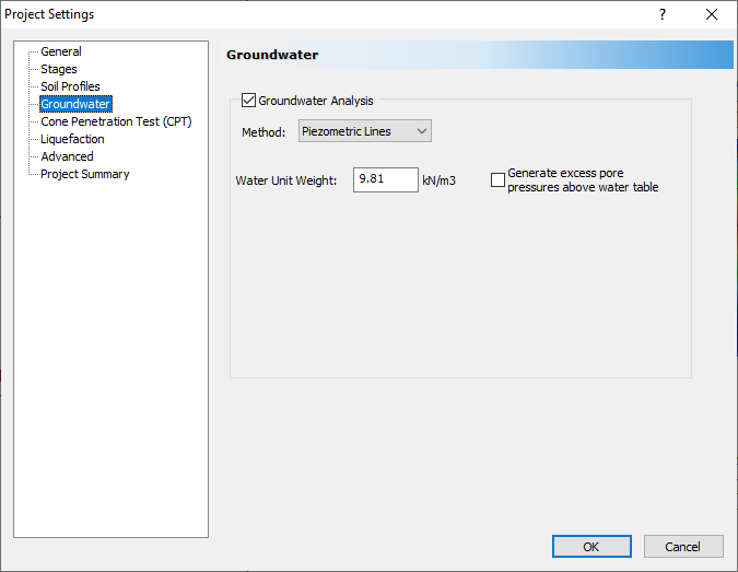
- Select the Groundwater tab, and select Groundwater Analysis with the Piezometric Line as the Method.
- Click OK.
Suppose the embankment is an extension and we are to raise an old road embankment. The following layers are expected to be constructed.
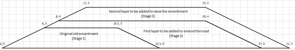
As shown in the figure above, we need to define three stages of construction in our model.
Note that this embankment feature does not support non-horizontal ground surfaces. In other words, if the ground surface is non-horizontal the embankment will still be added with a flat surface as the bottom.
3.0 Soils
3.1 Soil Properties
- Select Soils > Define Soil Properties

- Enter the following properties shown in the table below for the two soil layers:
- Make sure to uncheck the Secondary Consolidation Settlement option for every soil layers.
- In addition, the Bed Rock layer will not undergo any settlement so we will uncheck both Immediate Settlement and Primary Consolidation.
Soil Name |
Unit Weight [kN/m3] |
Saturated Unit Weight [kN/m3] |
K0 |
Immediate Settlement |
Primary Consolidation |
|||||
Es [kPa] |
Esur [kPa] |
Material Type |
Cc |
Cr |
e0 |
OCR |
||||
Loose Sand |
14 |
18.53 |
0.55 |
10000 |
10000 |
|
||||
Soft Clay |
18 |
20 |
0.3 |
20000 |
20000 |
Non-Linear |
0.4 |
0.04 |
1 |
1 |
Very Dense Sand |
21 |
21 |
1 |
80000 |
80000 |
|||||
Bed Rock |
18 |
18 |
1 |
|||||||
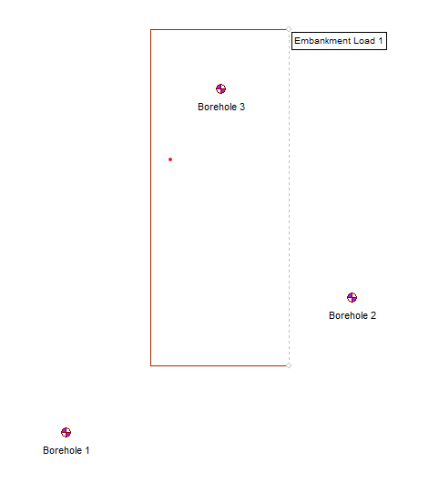
3.2 Boreholes
Now we will define the soil layers by adding three boreholes.
- Select Soils > Add Borehole

- In the Edit Borehole dialog, input the following Thickness values for the corresponding borehole:
Borehole 1
- Loose sand = 3
- Soft clay = 2
- Very dense sand = 14
- Bed Rock = 10

Borehole 2
- Loose sand = 3.5
- Soft clay = 12
- Very dense sand = 7
- Bed Rock = 10

Borehole 3
- Loose sand = 3.5
- Soft clay = 8
- Very dense sand = 6.5
- Bed Rock = 10

It is worth noticing that boreholes have different depths for every layer. The clay layer is thicker in Borehole 2, which makes the consolidation and overall settlement surrounding this borehole greater than the rest of the embankment area. You may also define the soil layers using top and bottom elevation points by unchecking Define Layers by Thickness and inputting the associated elevations.
4.0 Groundwater
- Select Groundwater > Add Piezometric Line

- Enter a Depth of 2.0 m and click OK.
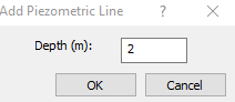
- Once the Assign Piezometric Line to Soil dialog appears, click Select All and then OK.
5.0 Loads
5.1 Embankment Cross Section
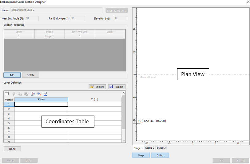
- Select Loads > Load by Zones
 to open the Embankment Cross Section Designer.
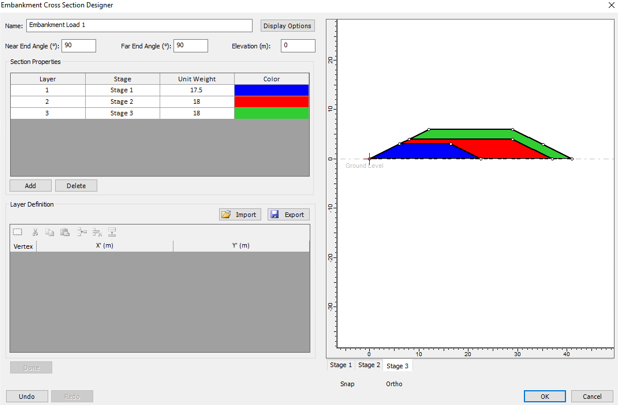
 - To add layers, select the Add button located below the Section Properties field. Using the table below, enter the following layer and stage:
- Once you have input all of the information shown above, click OK to input the coordinates of the embankment's bottom surface.
- Enter the following two points: {56,150}, {56,50}
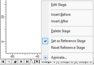
- The three stages will appear as tabs at the bottom of the drawing. Right-click on Stage 1 to choose it as a reference stage as the settlement of the stage is already finished and is not required for the new layers added in the road extension.
The Embankment Cross Section Designer dialog allows the users to enter the embankment cross section layers and their respective stages. The coordinates may be filled in directly using the coordinates table or may be plotted using the mouse in the plan view.
Layer |
Stage |
Unit Weight [kN/m3] |
Vertex |
X' |
Y' |
1 |
Stage 1 |
17.5 |
1 |
0 |
0 |
2 |
22.5 |
0 |
|||
3 |
16.5 |
3 |
|||
4 |
6 |
3 |
|||
2 |
Stage 2 |
18 |
1 |
6 |
3 |
2 |
16.5 |
3 |
|||
3 |
22.5 |
0 |
|||
4 |
37 |
0 |
|||
5 |
29 |
4 |
|||
6 |
8 |
4 |
|||
3 |
Stage 3 |
18 |
1 |
8 |
4 |
2 |
29 |
4 |
|||
3 |
37 |
0 |
|||
4 |
41 |
0 |
|||
5 |
29 |
6 |
|||
6 |
12 |
6 |
After inputting the above information, your embankment cross section should look like the following:
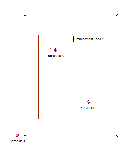
Your plan view should automatically update with a rectangular object as shown below:
6.0 Computation
6.1 Add Field Points Grid
- Select the Query > Add Field Point Grid
 option.
 - Choose the number of grid points desired. 400 field points are sufficient for this model.
- Click OK and you will be prompted to enter coordinates as we did for the Embankment Designer. For the Field Point Grid, you can either enter coordinates or use the plan view; we will just click and drag to cover an area slightly larger than the embankment itself. For reference, see below for the sizing of the field point grid.
6.2 Add Query Line
To calculate the overall settlement at each stage, a query line is chosen in each direction as shown in the layout above.
- Select Query > Add Line

- The query line chosen crossing is at around {35,100}.
The settlements are calculated immediately when the query lines appear. If contours of the settlement are required, an area for grid points may be added using the Auto Field Points Grid option or the Add Field Points Grid option (see previous section).
7.0 Results
The settlement contours and values for the query line will be immediately calculated and shown. You may see the settlement of each stage by clicking through the stage tab at the bottom.
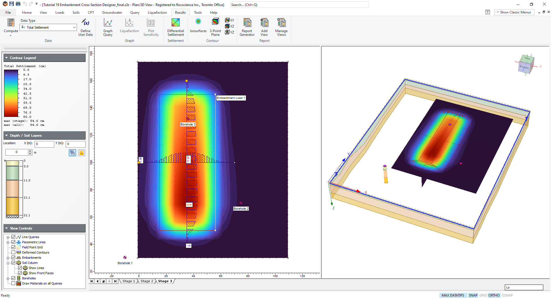
As expected, the maximum settlement occurs in the region closest to Borehole 2.
You can refer to other tutorials to learn how to handle other options for time dependence.
This concludes the Embankment Cross Section Designer tutorial. You may now exit the program.