Section Creator
With the Section Creator, you can create a unique section to create your model. The tool gives you more control over how you draw and define the soil profile. You can integrate borehole data to use as guides with the material layers of the section, giving more control over the material layers.
Please see details on how to use this feature with section creator tutorial.
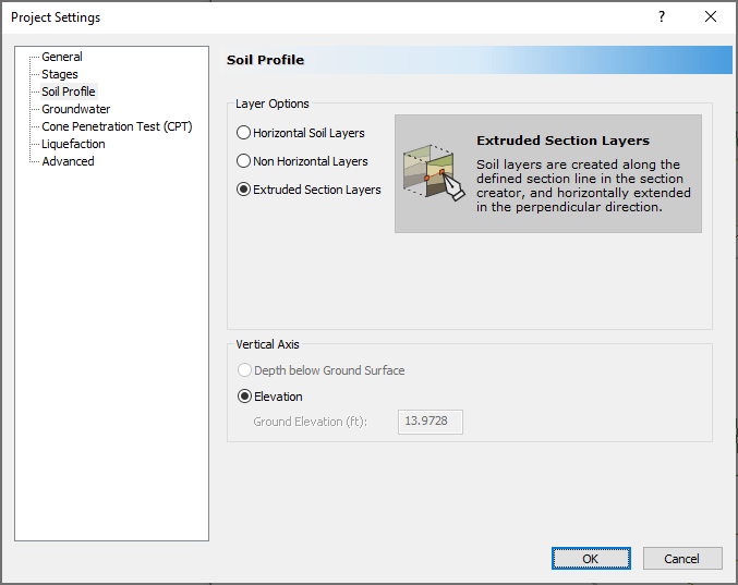
In order to use the section creator, you must first open the Project Settings and select Soil Profiles > Extruded Section Layers as shown below.
Then, Select Soils > Section Creator  to open the Section creator dialog.
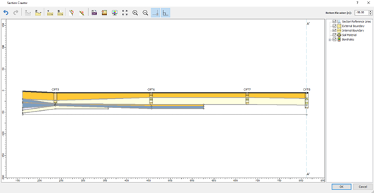
You will be prompted to draw a section on 2D viewer. You can enter the coordinates or draw freely to define the section line (A-A’). Note that currently, Settle3 allows one section line to be extruded along the perpendicular direction of section line A-A’.
Section creator controls:
- Draw ground surface

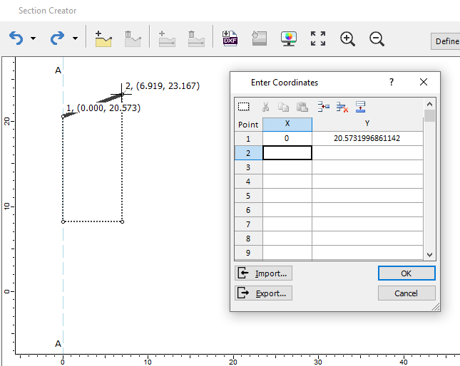
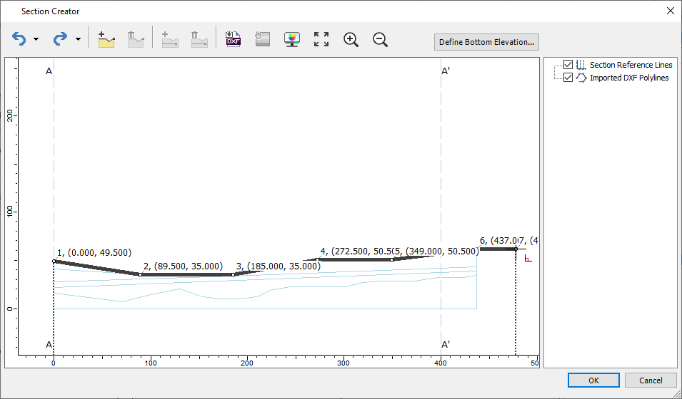
This option allows you to create the ground surface of the section (A-A’). You can either freely draw any lines within the dialog, or right-click after the layer is drawn and enter the coordinates as shown below.
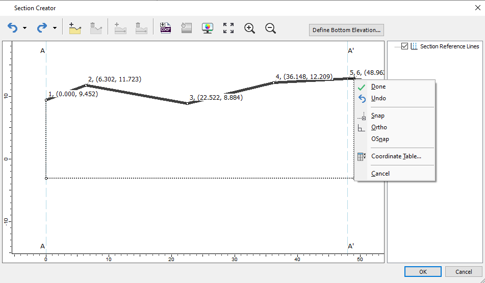
After drawing the line within the dialog, you can right-click to finish drawing the ground surface by selecting Done. If you right-click, you also have the option to undo the previous point drawn, or use the drawing tool features such as Snap, Ortho, OSnap, or coordinate table.
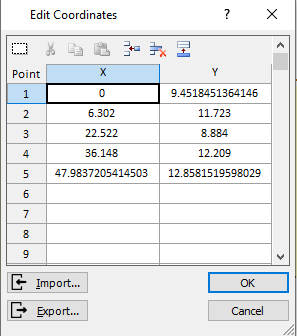
Coordinates of the drawn ground surface line are shown below.
Once the ground surface has been drawn, you can right-click > select Done. You will see the external boundary which extends the ground surface as you draw the boundary. By default, this is shown in dashed line but you can change this view by selecting display options within this dialog.
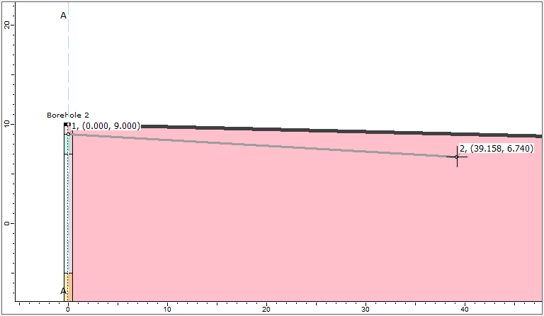
If you have multiple boreholes, you can also snap to top of the boreholes for creating the ground surface as shown below: 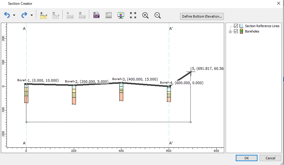
You can also draw the ground surface which extends beyond the section line (A-A’). The ground surface drawn represents your 3D model surface which will extend in perpendicular direction of the section line (A-A’).
- Undo/Redo
You can Undo/Redo any actions taken within this dialog by selecting this icon.
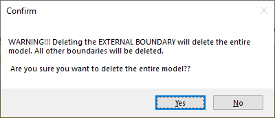
- Delete ground surface

After ground surface has been drawn, you can select Delete ground surface to delete any ground surface layer drawn within this dialog. You will be prompted with a warning sign that shows all other boundaries drawn within this dialog will be deleted.
- Define Bottom Elevation
This option allows you to define the bottom boundary of ground surface layer you have drawn. You can choose one of three options:
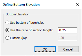
Use the bottom of boreholes allows you to create bottom elevation of the soil model to be the lowest boreholes. 'Use the ratio of section length' allows you to create bottom elevation that is proportional to the section length you have previously defined. You can customize the elevation by selecting the custom option and enter the elevation of the soil model using section creator.
- Draw internal boundary

This option allows you to draw internal layers within the ground surface layer created in Section creator.
When creating the internal boundary, the initial starting point will be snapped to either the left end or right end side of the ground surface layer.
You can freely draw any layers within the ground surface.
If you have boreholes in the model, you will be able to snap along each layer of the boreholes with its corresponding coordinates as shown below. Also, red dash lines will be shown while drawing internal boundary to project next point.
You can freely draw any shape you want from your boreholes. Some examples of the more complex soil profile with multiple boreholes that have discontinuous layers are as shown at the end of this documentation. Also, you can check the additional exercise of 22 - Section Creator tutorial which utilizes the use of this feature to create intersecting boundaries and discontinuous layers.
- Import DXF

This option allows you to import *.dxf file to your section profile. The *.dxf import reads all the polylines, whether they are closed polygons or open polygons. All the other types of information such as hatch, line color and text will be ignored. Note that these polylines are imported as guidelines to draw the layers. These are not imported as the ground surface/soil layer. Below is an example of imported *.dxf file and ground surface layer being drawn on top of the imported layout.
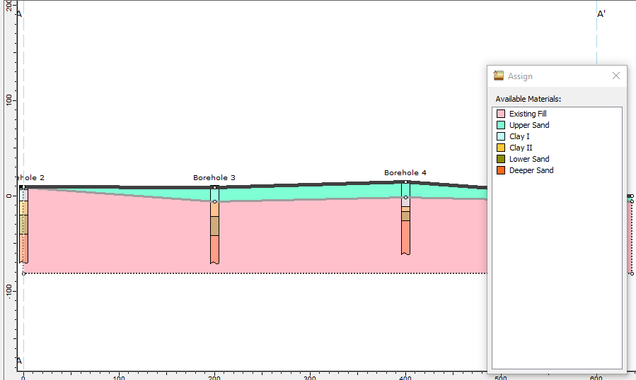
- Assign materials

This option allows you to choose and assign materials to the internal layer of the section. Select the material you would like to assign to the layer, and select the region separated by the layer boundaries.
- Display options

This option allows you to adjust and modify the settings for drawing tools within the Section creator.
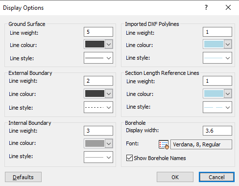
You can define the line properties of the ground surface layer, external boundary, and internal boundary. The imported DXF polyline, as well as section length reference lines, can also be modified as well.
For boreholes to be viewed in the section creator, you may choose the display width. This becomes helpful when trying to snap along the boreholes that are close to each other by reducing the display width of boreholes. You can also decide to show/hide the borehole names.
To go back to the default settings, simply select Defaults button and it will bring you back to the default setting.
- Zoom features (Zoom All, Zoom in, Zoom out)
You can zoom in/out in the Section creator dialog or zoom all to fit the model to the dialog window.
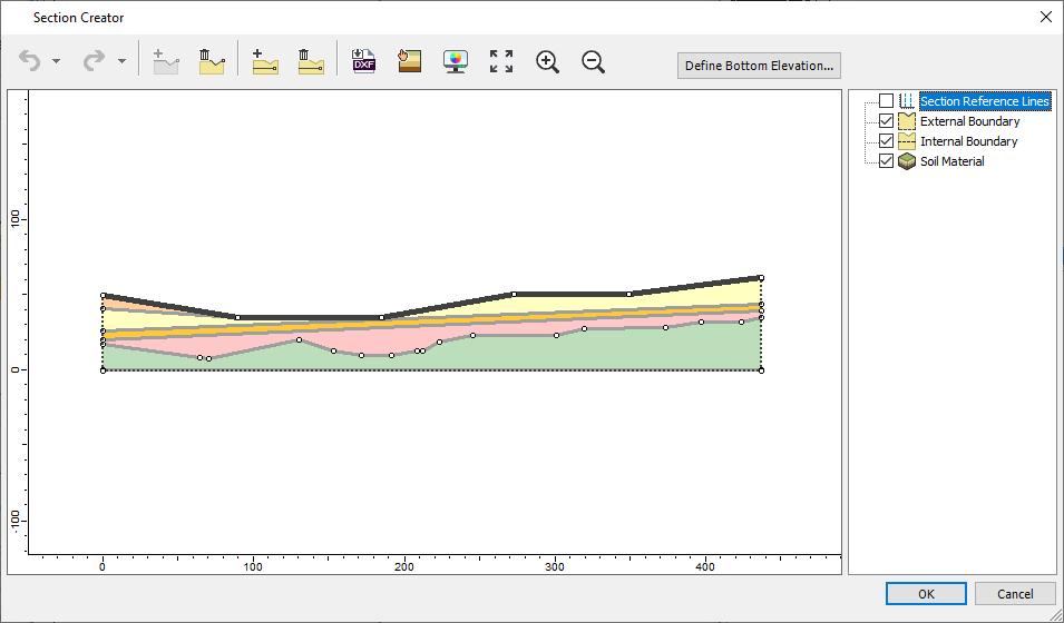
- View Controls
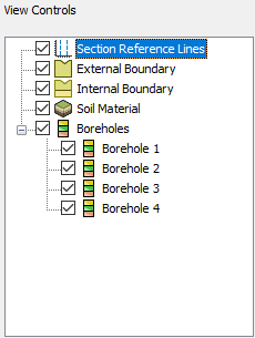
You will see a list of items that are drawn within the section creator. Select the box to toggle on/off these items to be displayed in the section creator.
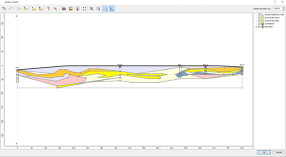
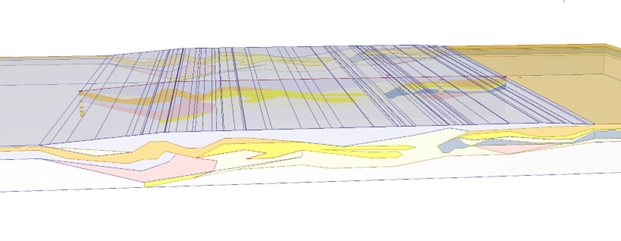
Below are some examples with Section creator (without and with boreholes):
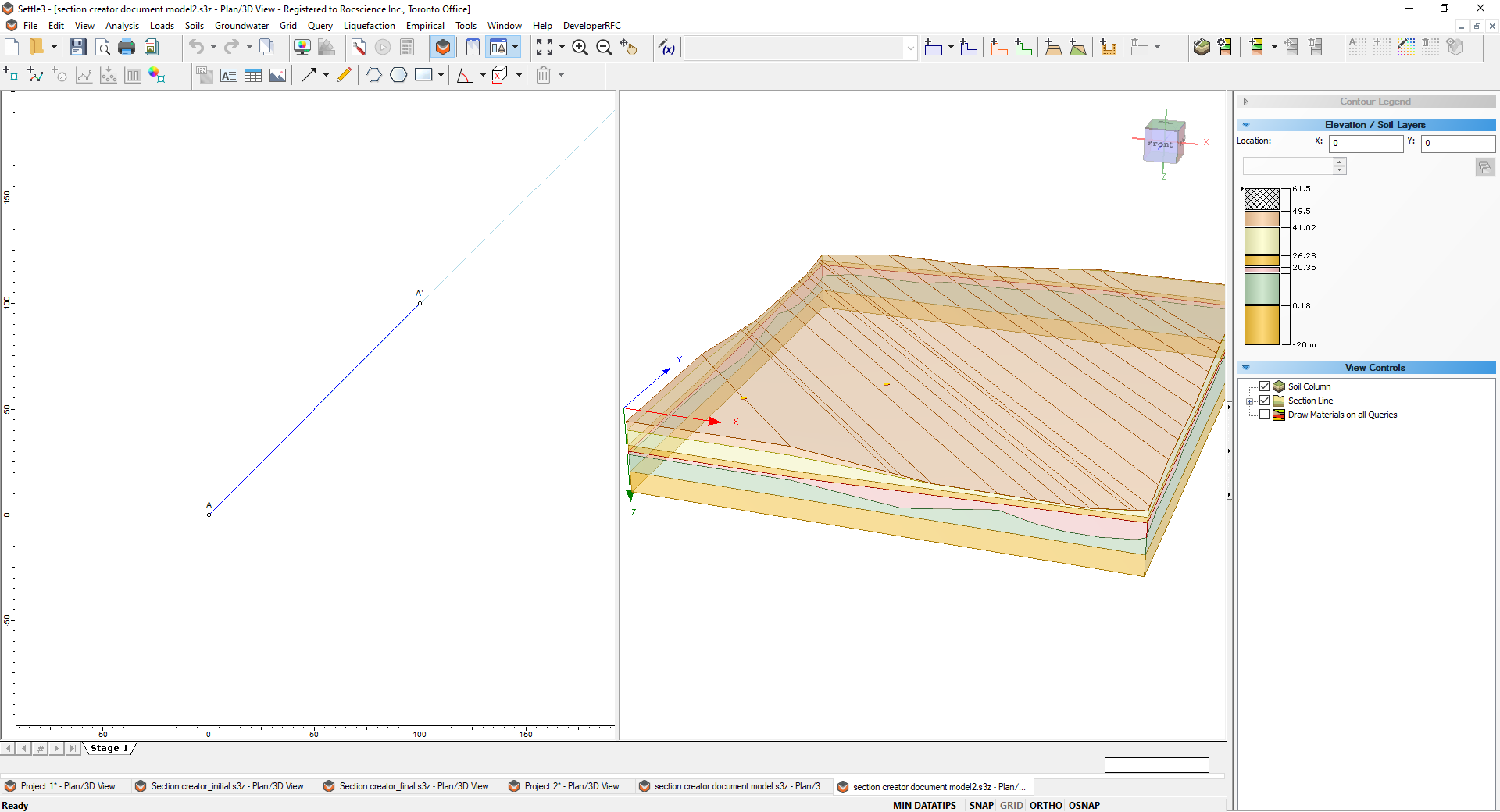
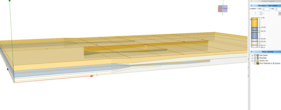
As shown in the above figure, the view controls allow you to view the 2D section A-A’ you have created in the 3D viewer.
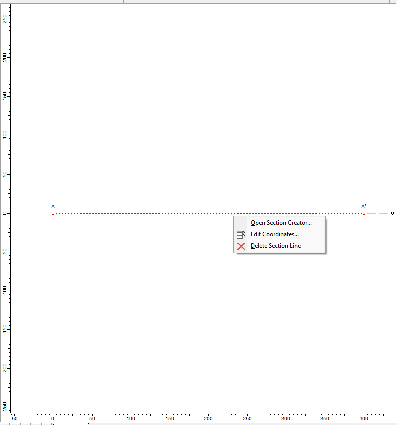
If you want to modify the section creator, you can either right-click on the section line (A-A’) and select section creator or select Soils > Open Section Creator. You can also change the coordinates of the section line A-A'.
Please refer to the 22 - Section Creator tutorial which shows the step-by-step creation of the model with this feature.
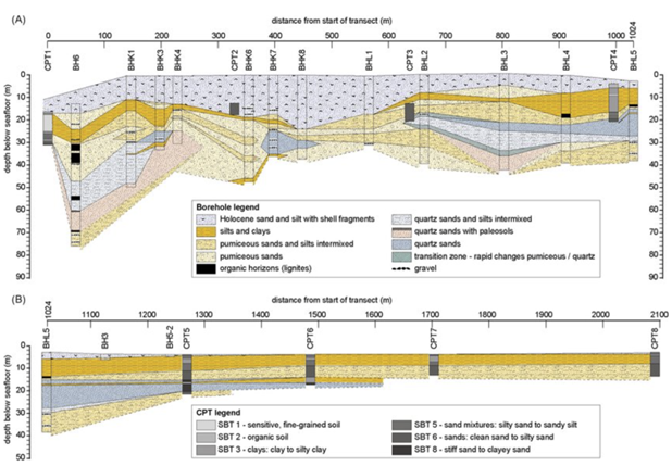
Previously, you would have to draw the section which extends from one end to the other end with a continuous line and this presented some challenges and limitations when modelling engineering cases with discontinuous soil layers, sinkholes, utility trenches, pipeline structures, etc. These challenges are now resolved in the section creator enabling you to freely draw any shape you want from your boreholes. Some examples of the more complex soil profile with multiple boreholes that have discontinuous layers are as shown below.
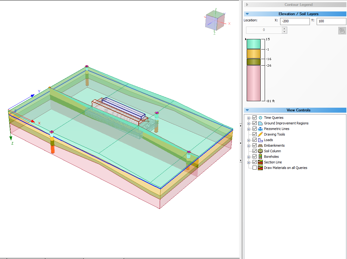
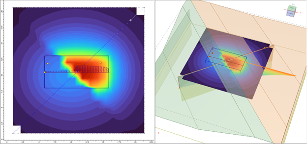
With the improved section creator, a similar profile can be modelled using the section creator in Settle3. After the soil model is created in the section creator, you can apply loads and add query point, query lines, or field grid point to see the settlement analysis results. However, note that the settlement is calculated based on the assigned soil material along the depth/elevation of the soil profile. For instance, there’s a stiff soil layer on the left side of the soil profile, followed by the softer soil region on the right side of the load. With the use of improved section creator, you can freely model this soil condition with the use of vertical boundaries in the section creator.
The soil materials can be assigned with different material properties to visualize the difference in settlement analysis results which corresponds to the soil material below the load along the depth/elevation of the soil model.
The model below shows the soil profile created using vertical boundary which allows users to define two distinct soil profile in a model. Settlement on the right side of the load is more prevalent than the settlement on the left section of the load as shown below in Figure C.
Therefore, you can now freely create any geometry as you like to define in the section creator, which you can then extrude into a 3D soil model for settlement analysis.
Section Creator and Excavations
When you use Add Excavation with the Section Creator, the layers under the excavation needs to be consistent throughout the excavated region. For instance, if one of the vertices of the excavation has only 2 layers while the other vertex has has 3 layers, Settle3 will not be able to calculate the effective volume of soil weight removed.