Pile Types
The Define Pile Types option is available through Piles > Pile Types  .
.
Pile Types are made up of Pile Sections whose properties are defined in the Pile Section Properties dialog.
The properties and options available for a pile type are dependent on the analysis option selected, as is explained in the table below.
| RSPile | Pile Section Properties | Pile Type | |||||
| Analysis | Cross-Section | Material Type | Material Properties | Multiple Sections | Bell Section* | Tapered Section | Helix Section |
| Driven | Pile Pipe Closed End | Not Applicable | Not Required | YES | NO | YES | NO |
| Pile Pipe Open End | YES | NO | YES | NO | |||
| Timber | YES | NO | YES | NO | |||
| Concrete Pile | YES | NO | YES | NO | |||
Rolled Section |
YES | NO | NO | NO | |||
| Bored | Circular | Concrete | Concrete strength | YES | YES | NO | NO |
| Square | YES | NO | NO | NO | |||
| Rectangular | YES | NO | NO | NO | |||
| Helical | Square Solid | Not Applicable | Not Required | YES | NO | NO | YES |
| Square Hollow | YES | NO | NO | YES | |||
| Circular Solid | YES | NO | NO | YES | |||
| Circular Hollow | YES | NO | NO | YES | |||
| Axial/ Lateral | Circular | Elastic | Modulus | YES | YES | YES | NO |
| Rectangular | YES | NO | YES | NO | |||
| Pipe | YES | NO | YES | NO | |||
| Typical Section | YES | NO | NO | NO | |||
| User Defined | YES | NO | NO | NO | |||
| Circular | Plastic | Modulus Mxy Mxz | YES | YES | YES | NO | |
| Rectangular | YES | NO | YES | NO | |||
| Pipe | YES | NO | YES | NO | |||
| Circular | Reinforced Concrete | Concrete strength | YES | YES | NO | NO | |
| Rectangular | YES | NO | NO | NO | |||
| Circular | Prestressed Concrete | Concrete strength | YES | NO | NO | NO | |
| Rectangular | YES | NO | NO | NO | |||
Notes:
- Group analysis has the same Pile Type features as Lateral/Axial analysis
- *Bell Section cannot exist by itself and can only be added as the bottom-most section
- Skin friction is ignored along a Bell Section
- P-Y and Q-Z curves of a bell section are obtained using the actual bell dimensions
- The structural stiffness of a bell section is calculated using the stem diameter
- The bell obtains its properties from the section immediately above it including any reinforcement design
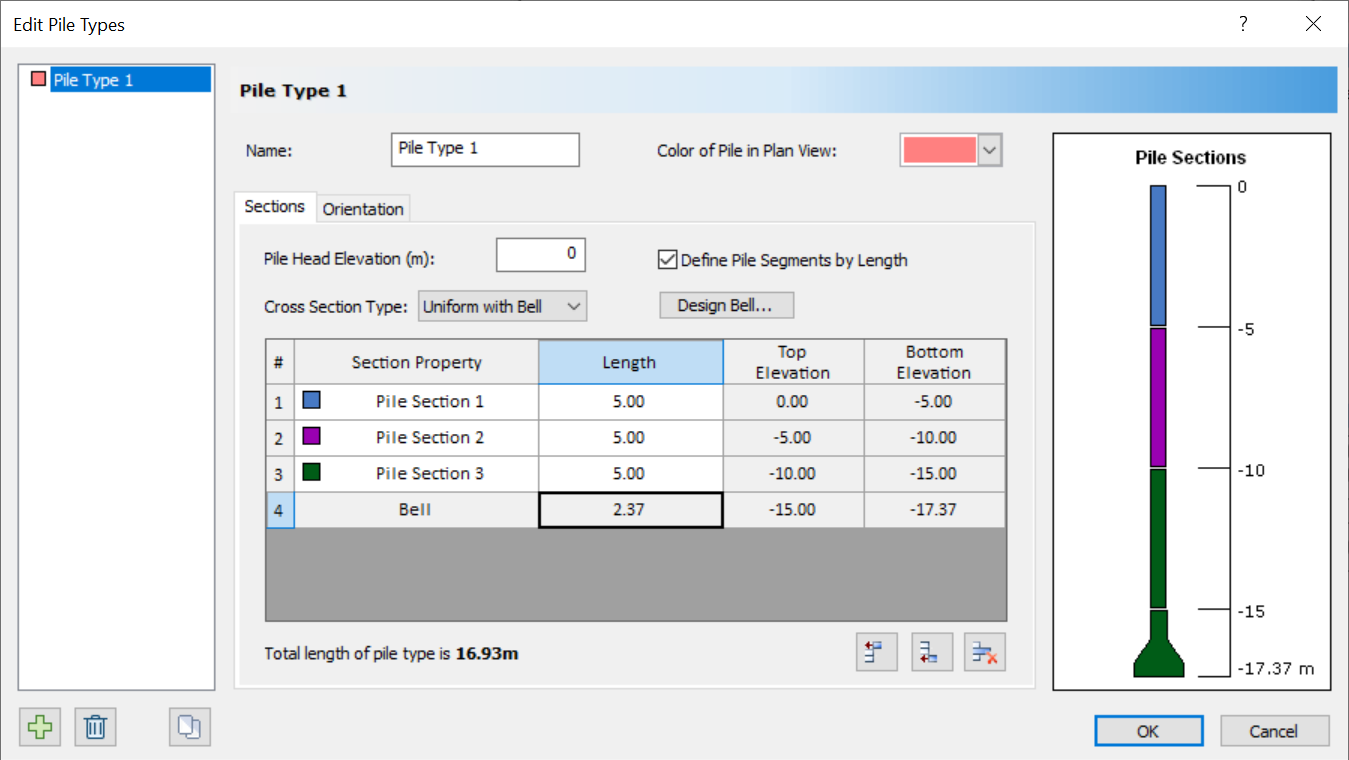
The Edit Pile Types dialog is separated into two sections which are explained below:
- Sections
- Orientation
Pile Sections
The Section tab allows users to construct a Pile Type using Pile Sections. In this tab users can define the:
- Pile Head Elevation
- Cross Section Type
- Number of Sections
- Length of each Section
- Bell geometry and tapering
- Helices geometry
BELLS
Depending on the type of analysis being done, a bell can be added and defined using the Design Bell option.
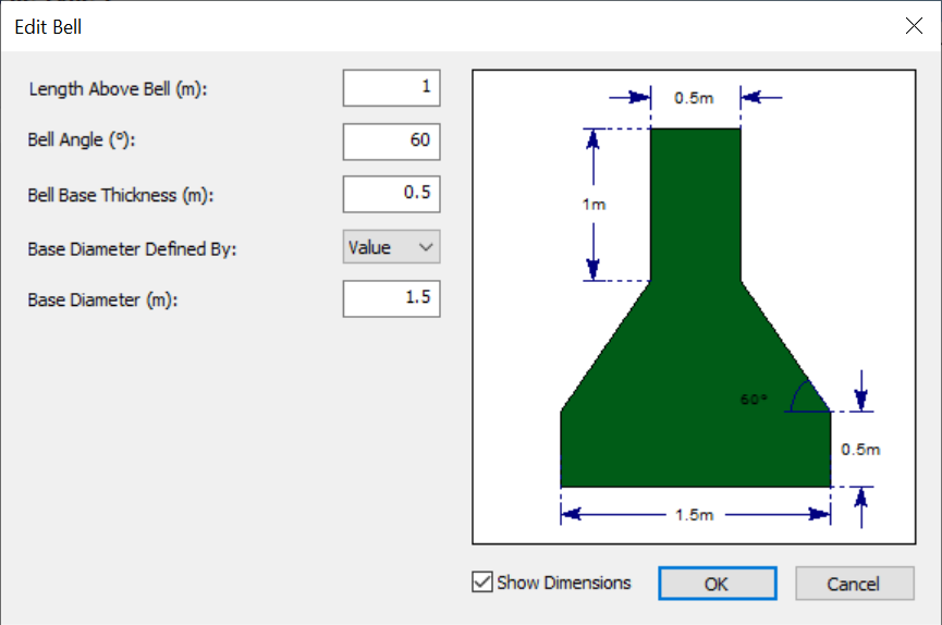
In this dialog users can define:
- Length Above Bell
- Bell Angle
- Bell Base Thickness
- Base Diameter
When adding a bell it should be noted:
- Bell Sections cannot exist by themselves and can only be added as the bottom-most section of the pile type
- Skin friction is ignored along a Bell Section
- P-Y and Q-Z curves of a bell section are obtained using the actual bell dimensions
- The structural stiffness of a bell section is calculated using the stem diameter
- The bell obtains its properties from the section immediately above it including any reinforcement design
Assumptions for different analysis options
Certain assumptions are made for each type of analysis when a bell is added to a pile type:
Lateral
- Skin friction is ignored along a bell section
- P-Y curves along a bell section are obtained using the interpolated bell diameter
Axial
- T-Z is ignored along a bell section
- Q-Z is obtained using the bell base diameter
- The structural stiffness of a bell section is computed using the stem diameter
Bored Analysis
- Skin friction is ignored along a bell section
- Pile capacity along a bell section is obtained using the interpolated bell diameter
HELICES
If a Helical analysis is being performed, users can define helices along the shaft using the Define Helices option.
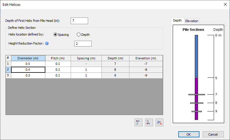
The depth of the first helix is controlled by the Depth of First Helix from Pile Head input box at the top of the dialog.
For subsequent helices, the user has the option to define the helix position by spacing from the helix above or depth from pile head.
If the user defines by:
- Spacing: The depths and elevations of the helices will be automatically calculated based on the specified spacing from the helix above
- Depth: The spacing will be calculated based on the difference between the current helix depth and the helix above
The height reduction factor is used to determine the length above the first helix which is ignored in uplift. For more information, please see the Helical Pile Theory Manual.
- The depth of the first helix must be within the range of 0 to the total length of the pile. An error message will appear if an invalid depth is entered.
- All entries in the grid must be positive values greater than 0. If the user attempts to enter a negative value for any of the inputs in the grid, an error message will be shown at the cell with the invalid number.
- Helices must be defined in sequential order, with each subsequent helix positioned deeper than the one above it. If the helices are entered out of order, a warning will be displayed.
- If the specified spacing or depth causes any helices to overlap, a warning message will be displayed.
- A helix spacing less than or equal to the pitch will result in the overlapping helices warning. Ensure that the spacing between the helices or the difference between the current and previous helix depths is greater than the pitch.
- Helices must be positioned within the shaft boundaries. If the specified spacing or depth causes a helix to fall outside the shaft, the user can receive error messages in two locations: within the helix dialog at the cell containing the invalid depth or spacing, or in the pile types dialog if modifications to the pile length cause the helices to fall out of range.
Orientation
The orientation inputs are used to specify the pile batter and orientation in 3D space. Two options are available:
- Alpha/Beta
- Alpha - Rotation of pile around z-axis, clockwise from the y-axis
- Beta - Batter angle of pile, clockwise from y-axis
- Theta - Rotation of pile around the central axis of the pile
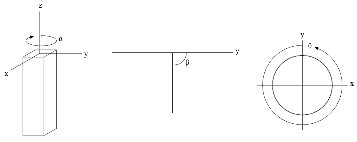
From left: alpha, beta, theta
- Vector
- XYZ - Direction vector coordinates. The normalized unit vector of the input vector is calculated.
- Rotation Angle - the angle of rotation (clockwise, in degrees) of the pile section about the z-axis. (0 degrees if no rotation).
Notes on Ground Slope and Pile Batter
- Ground Slope and Pile Batter are only one of the options for defining a battered pile / sloping ground. T-z and Q-z multipliers can be used to analyze axially loaded (battered) piles in sloping ground. Similarly, p-y multipliers are more commonly used to analyze laterally loaded (battered) piles in sloping ground.