Tunnel Design with Boreholes
1.0 Introduction
This tutorial demonstrates how to use Tunnel Designer with boreholes in RS3. The model is created with three user-imported boreholes. Each borehole has a different soil profile with different elevations. The tutorial will also demonstrate how to define a tunnel using coordinates and a general 3D path.
To start the tutorial:
- Select Files > Recent > Tutorials folder in the RS3 menu.
- Open Tunnel designer with borehole-starting file.rs3v3.
2.0 Geometry
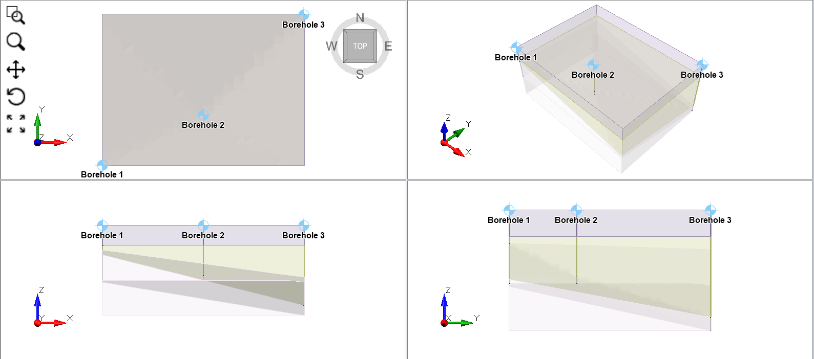
You will see the geometry with three boreholes defining the soil layers. Now we will use the Tunnel Designer on the soil model with the defined boreholes.
2.1 Borehole Data
Just for reference, if you want to see the borehole profile or make changes to the borehole data later:
- Select:
Materials > Borehole manager.
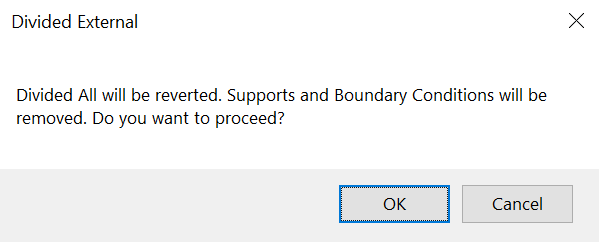
Divide External dialog box - You will see the message for divided external. Click OK and you will be able to see the borehole editor. It is important that after you see the borehole profile, you must apply Divide all
 to the geometry.
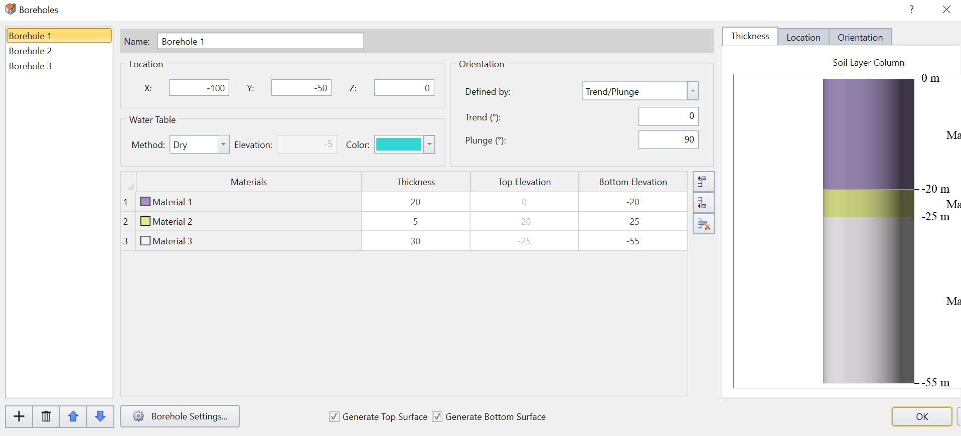
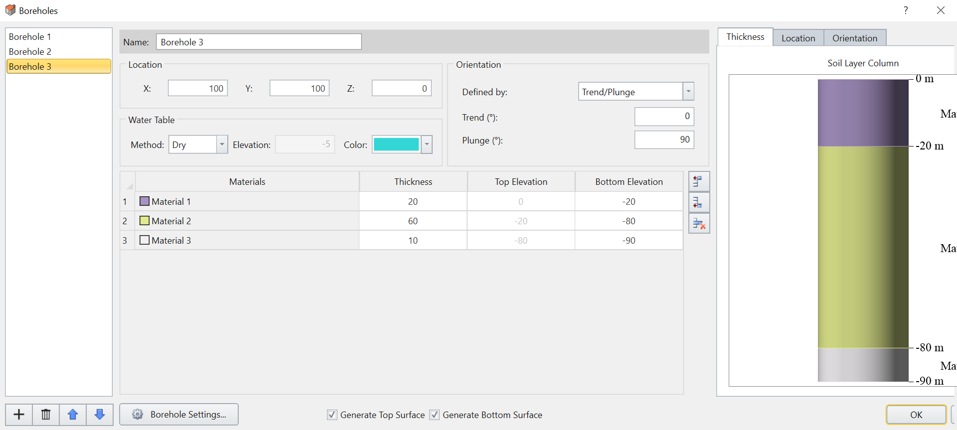
The borehole data is shown below:
Borehole 1:
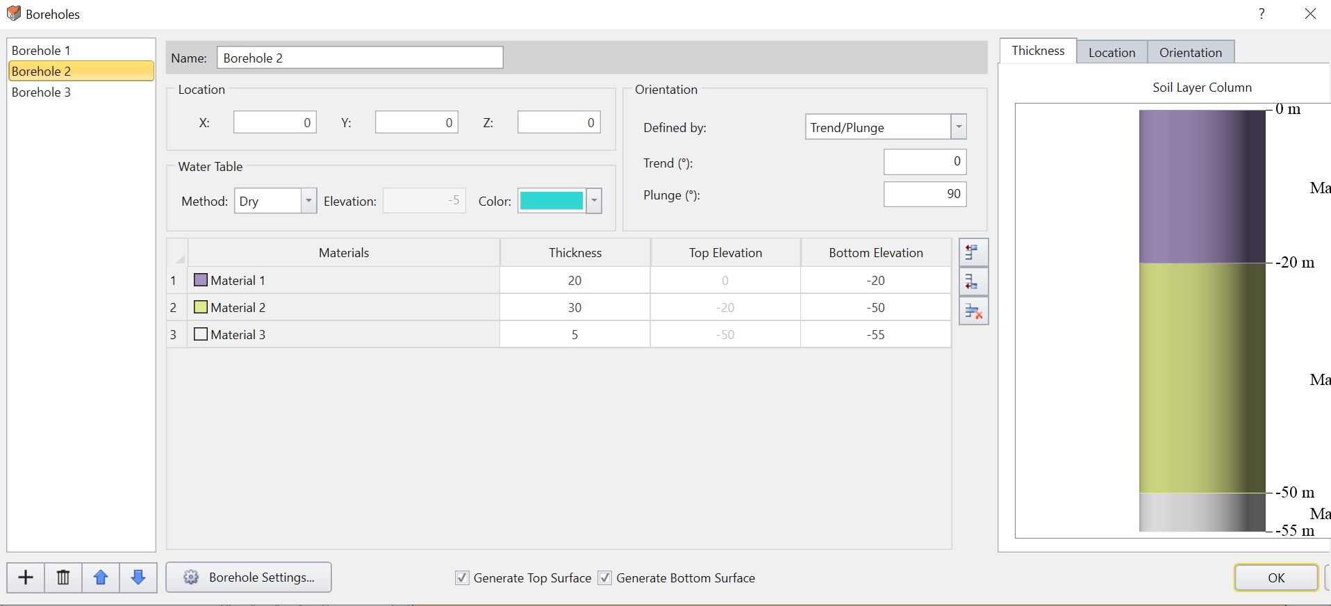
Borehole 2:
Borehole 3:
- After reviewing the boreholes, select Geometry > 3D Boolean > Divide All geometry to revert back to the original initial file we had.
3.0 Tunnel Design
3.1 TUNNEL PROFILE
- Launch Tunnel Designer tool.
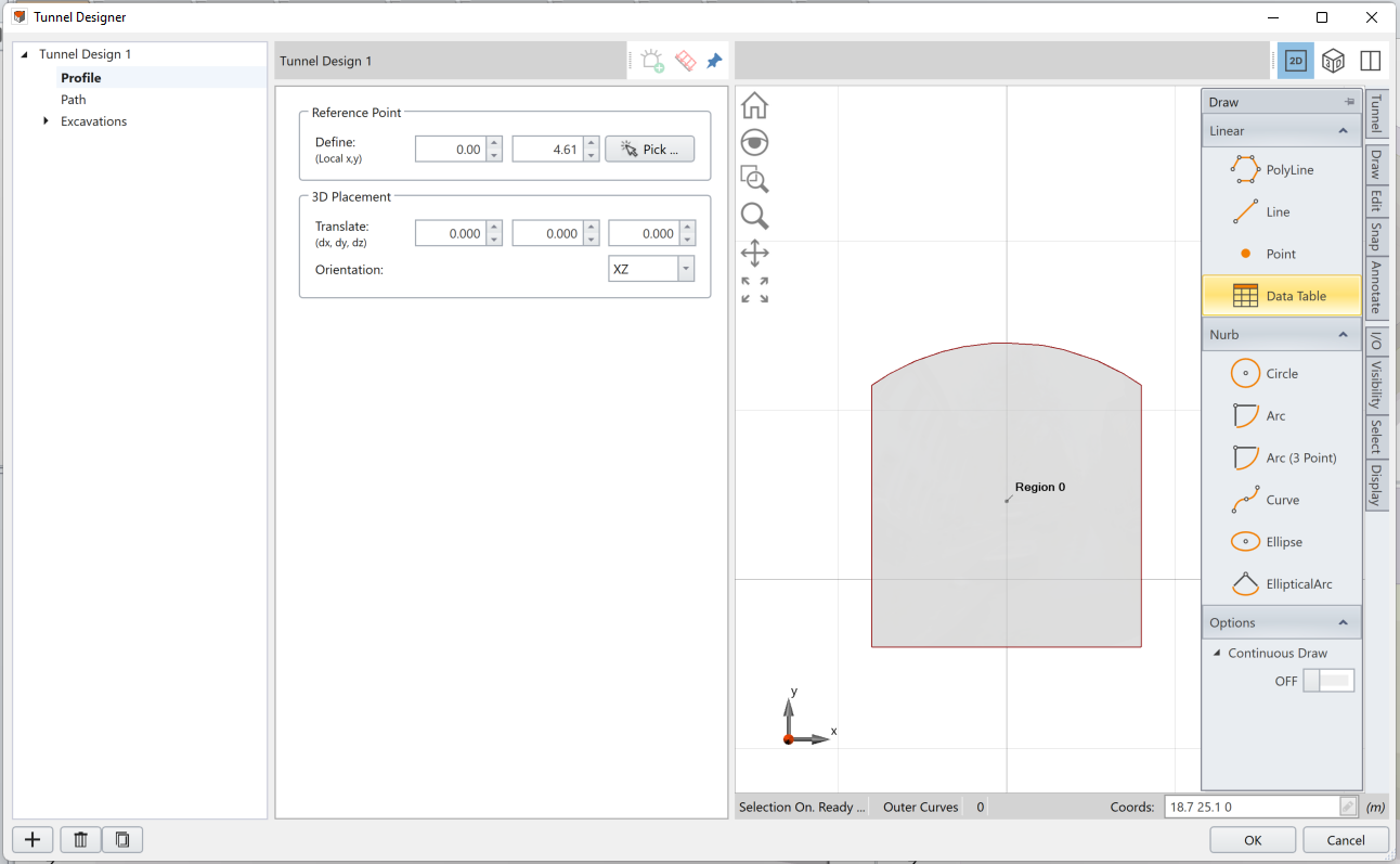
- Use the Tunnel Shape tool to select a predefined tunnel shape as the tunnel’s outer contour. On the right side of the Tunnel Designer, select Tunnel > Tunnel Tools > Tunnel Shapes.
- The default shape is tunnel with a round top and square bottom. Click OK.
After the outer contour of the tunnel is created, we will create a region of excavation that is defined in coordinates.
- Under Draw > Linear on the right-hand side of the dialog, select Data Table.
- When the spreadsheet tool opens, select Open. Then, open the spreadsheet within the tutorial folder with startfile_line.csv which should be:
- (-12, 4)
- (-4, 0)
- (4, 0)
- (12, 4)
- (-12, 4)
3.2 TUNNEL PATH
Next, we will design the path.
- Select: Path = Coordinates (2D/3D) and click Data.

- You will be prompted with a spreadsheet. Open the startfile_path.csv. The data should be:
- (0, 0, 0)
- (20, 50, 0)
- (10, 100, 0)
- Select OK and you will see the tunnel path created in the dialog as shown below:

- You can now select Regions in the excavation menu on the left to divide the regions of excavation. Make sure you are in Region 0, and enter the following values for the excavation sequence:
- Sequencing Method: sequential
- Sequence in: 40 (m) sections
- Every: 1 stage(s)
- Stage Offset: 1 stage(s)
- Press Apply. You will see the results as shown below:

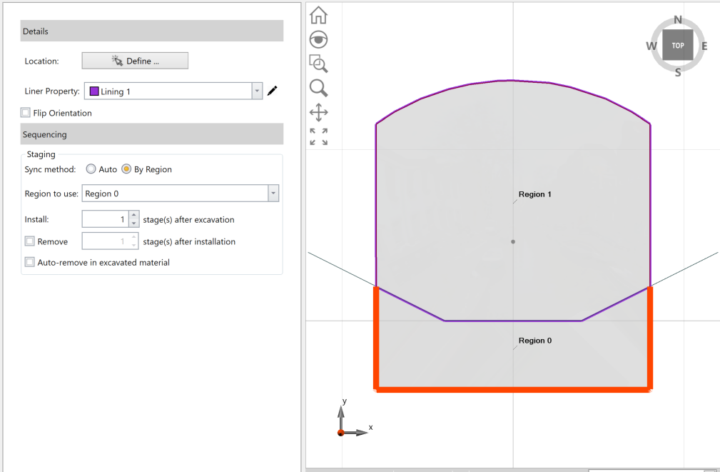
- Now select Region 1, and enter the following values:
- Check Excavation Sequence Checkbox
- Sequencing Method: Sequential
- Sequence in: 40 (m) sections
- Every: 1 stage(s)
- Stage Offset: 0 stage(s).
- Press Apply and you will see the top side of the staged excavation.

3.3 SUPPORT
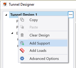
- Select: Tunnel Design > Add support.
- Then, in the Supports drop down, select Add Liner on Perimeter.
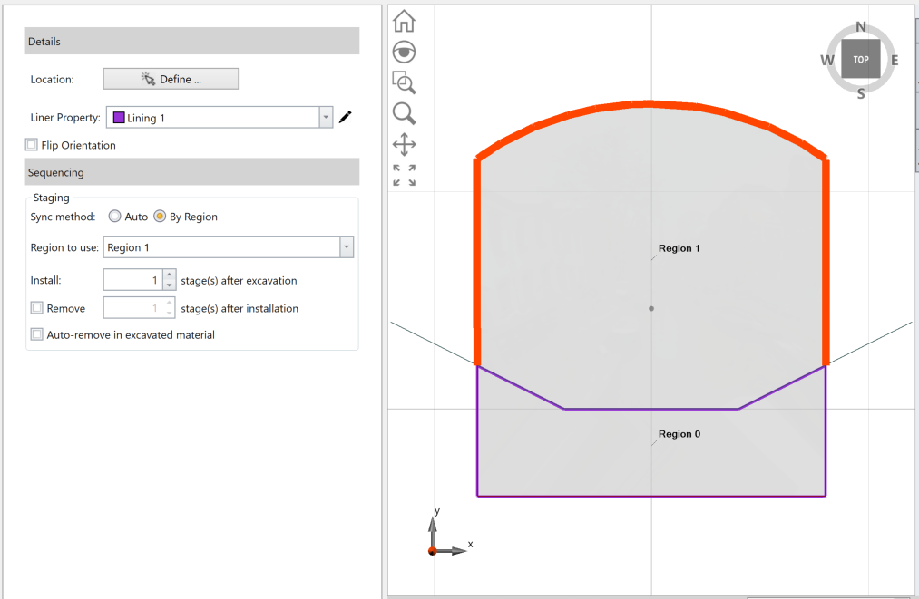
- For the Location, click Define. Then select the perimeter of region 1 (left side, top, and right side of region 1).

- For sequencing, choose the following inputs:
- Sync method: By region.
- Region to use: Region 1
- Install: 1 stage(s) after excavation
- Uncheck remove checkbox.
- Under the Supports drop down, we will create another liner. Select Supports > Add Liner on Perimeter. The liner on side2 will show on the left menu.
- Select: Location > Define.
- Now we will select the perimeter of the bottom region. Select the left side, bottom, and right side of the region 1.

- For sequencing, choose the following inputs:
- Sync method: By region.
- Region to use: Region 0
- Install: 1 stage(s) after excavation.
- Uncheck remove checkbox.
- Under Supports drop down, we will create another liner. Select Supports ... > add Liner on Perimeter.
- For Location click Define. Then, select the three polylines intersecting the regions. The liner should be applied as shown below:

- For sequencing, choose by region.
- Sync method: By region.
- Region to use: Region 1
- Install: 1 stage(s) after excavation.
- Check remove checkbox: select "1 stage after installation"
We will now add final liner at the intersecting line between region 1 and region 0.
Now we will double-check the inputs for each liner.
Liner 1:
Liner 2:
Liner 3:

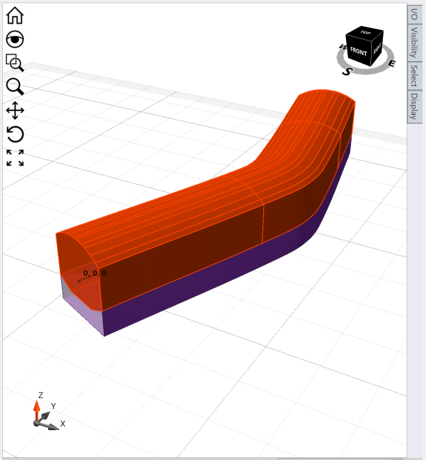
When you click on 3D on top of the modeller view, you can see the tunnel you have designed in 3D view as shown below:
3.4 ADD TUNNEL
Now we will be applying the tunnel to the soil geometry.
- Select: Tunnels > Add a Tunnel.
- An Add Tunnel dialog will pop up. Change the name to 'Tunnel 1'. Make sure the designed tunnel is based on ‘Tunnel Design 1’ and is applied in Location as 5, -40, -50 for x,y,z locations as also shown below:

- Click OK and you will see the tunnel applied in the soil model.
Now, we will do the Constrained divide all which intersect tunnels with the soil model as external geometry.
- Select: Tunnels > Constrained Divide All.
- Set the divide all parameters to Default and click OK. You will see the final model as shown below:
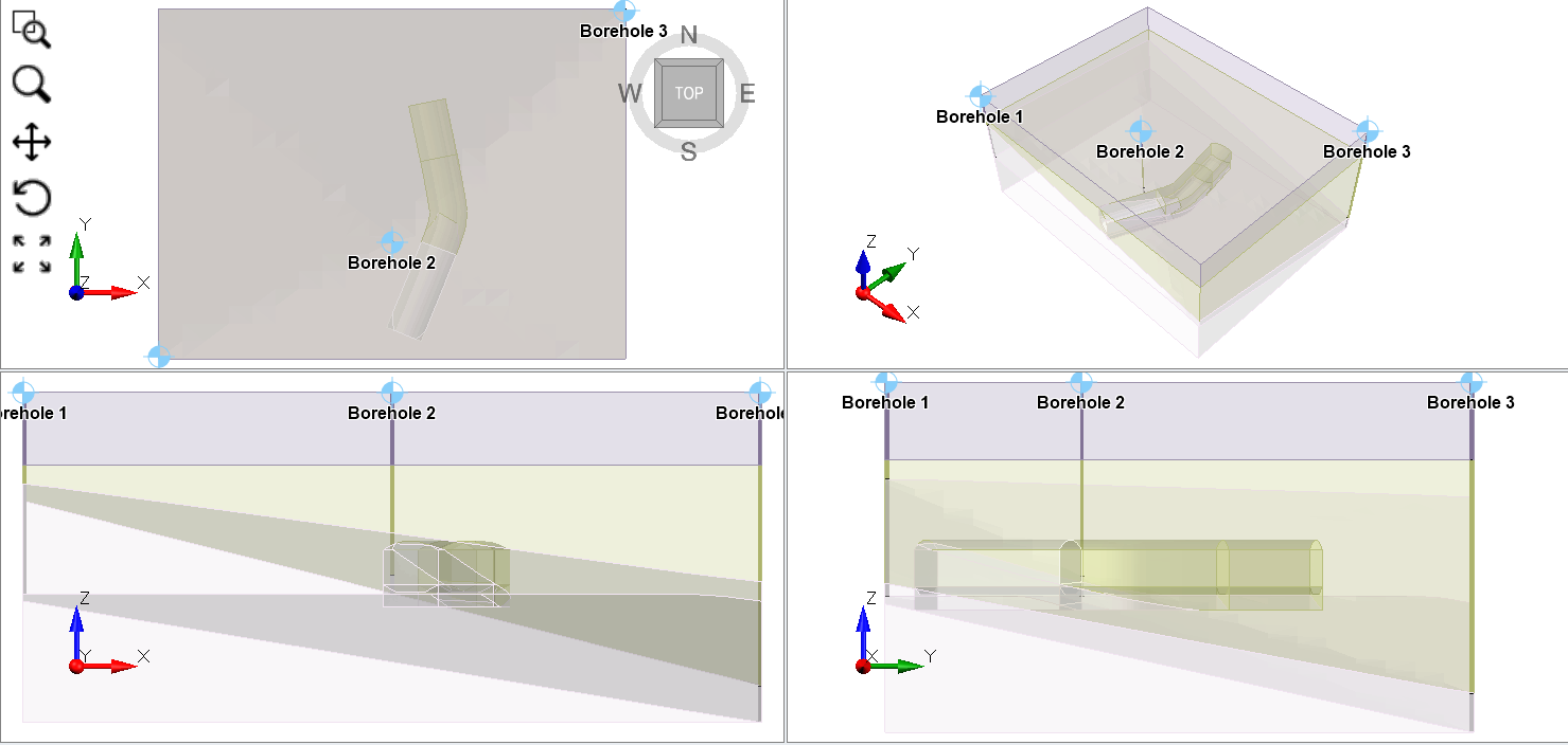
Note that when we do Constrained divide all, the tunnels intersect with the geometry of the soil model. Also, the tunnel properties are derived from soil properties that are defined by boreholes.
4.0 Restraints
We will now apply restraints to the model.
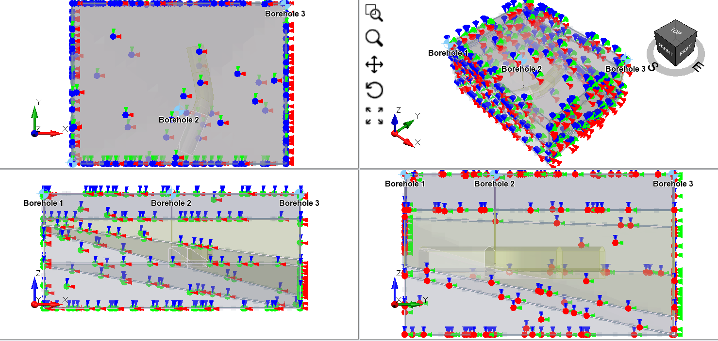
- Go to Restraints workflow tab

- In the menu, select Restraints > Auto restraint (underground). You will see the model as shown below:
5.0 Mesh
- Go to the Mesh workflow tab

- Select Mesh > Mesh. You will see the mesh applied to the model.

6.0 Compute
- Select the Compute workflow tab.
- Click Compute

7.0 Results
- Go to the Results workflow tab

- Select: Interpret > Show excavation contour. Make sure to hide the exterior contour plot on visibility tree and excavation contour plot is visible.

- In the contour option on right side, we will first check the total displacement at the excavation. Select Solids > Total displacement.
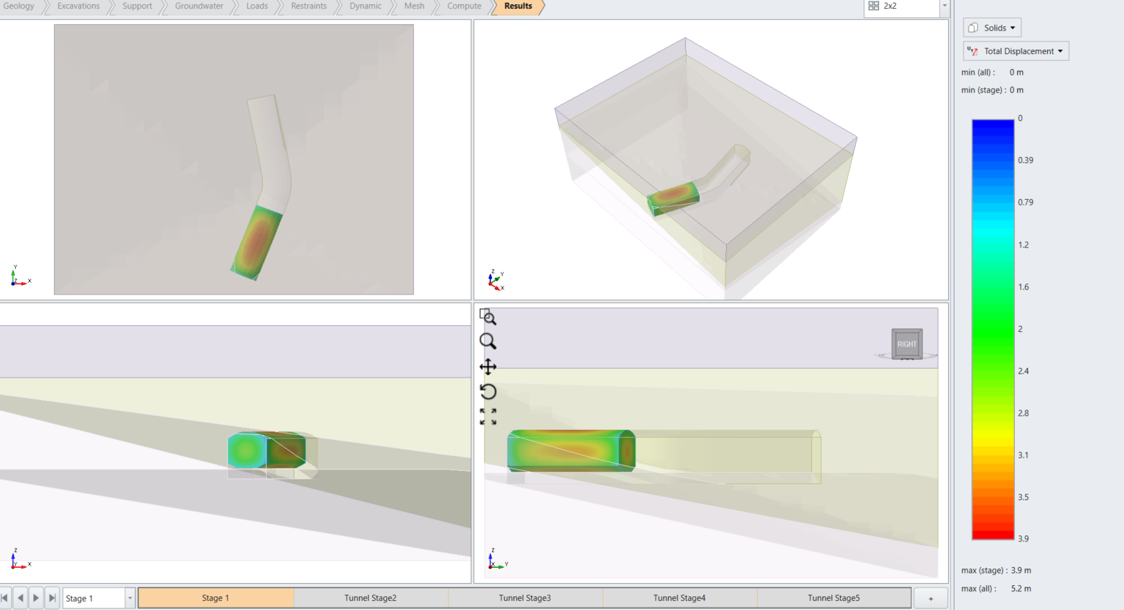
At stage 1, you will see the tunnel experiencing total displacement at the sides. The progression of stages with excavation can be shown by shifting through different stages. At stage 5, you will see the total displacement of the tunnel as shown below:
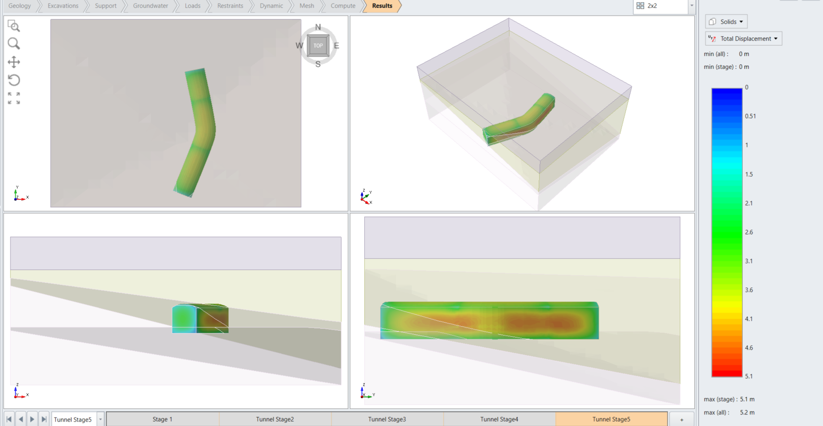
As expected, the total displacement occurs at the base of the tunnel. We will also see the force demand on the supports around the tunnels. Change the results type from Solids to Liners. Then, we will first check the axial force in X direction.
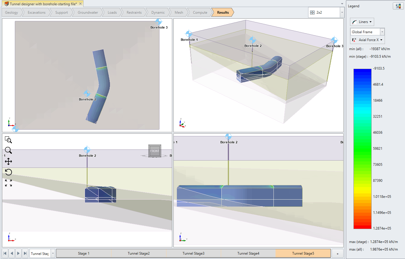
As you can see, there is increase in axial force at the bent path at the last stage of the tunnel excavation. We will also check the moment in X direction as well.
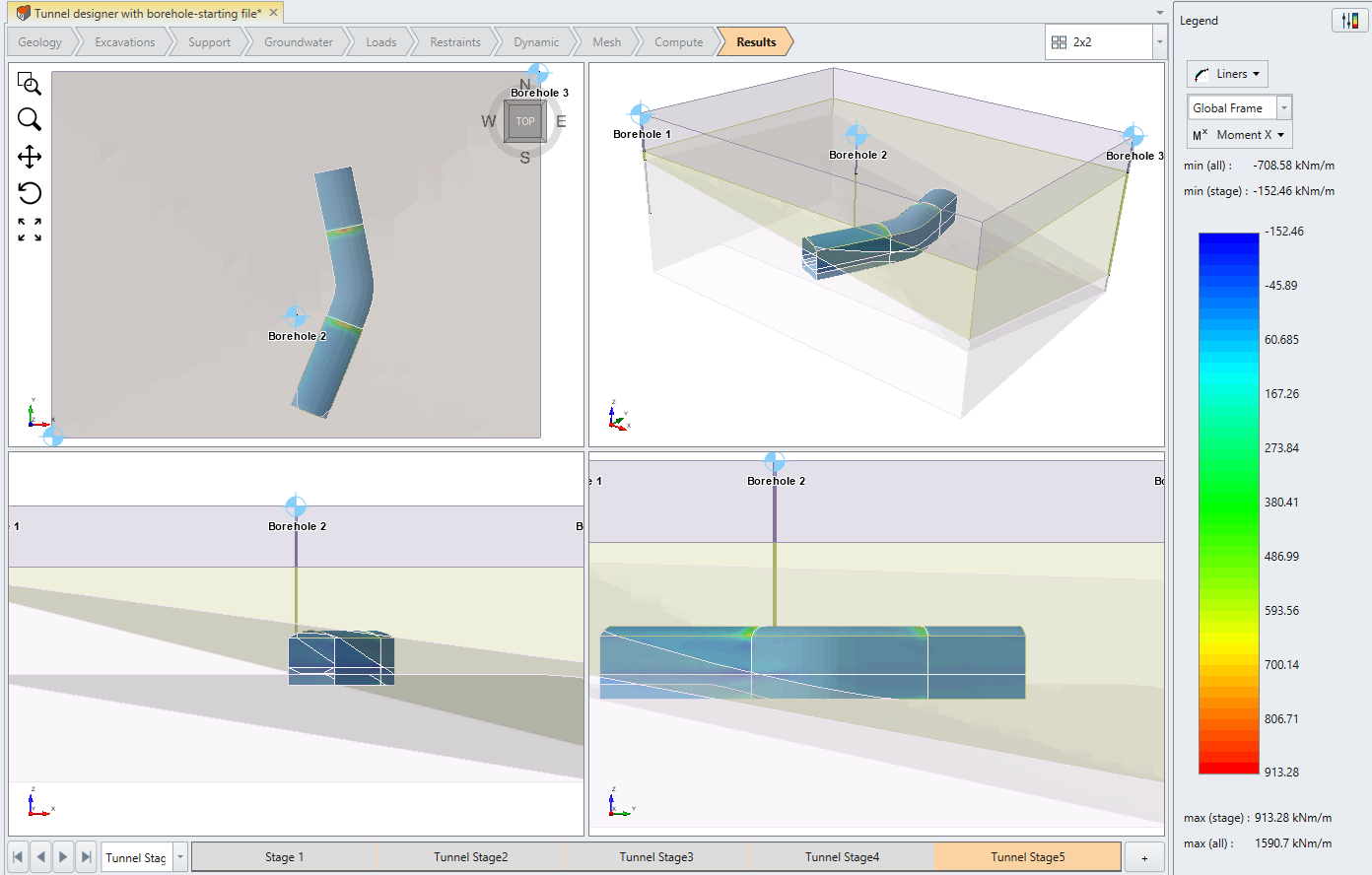
You can continue to explore different variables of interest with the results, whether it may be stress distribution of soil or liner force or moments. This concludes the tutorial of tunnel designer with boreholes.