Sequence Tunnel Design
1.0 Introduction
In this tutorial, we introduce the new Tunnel Designer Tool in RS3 M+. This tool allows users to create tunnels with various shapes, supports, staging excavation, and more. We introduce the basic features of the Tunnel Designer with sequenced tunnelling. Specifically, we will model a circular cross-section excavation in multiple stages with beam supports for typical tunnel excavation.
To start the tutorial:
- Select Files > Recent > Tutorials Folder in the RS3 menu.
- Open the Tunnel_sequence_designer-starting file.rs3v3.
2.0 Tunnel Design
2.1 CROSS-SECTION DESIGN
- Select: Tunnels > Tunnel Designer
You will see the Tunnel Designer dialog. On the right-hand side of the menu, you will see the construction tools available for you to draw/edit the cross-section geometry of the tunnel. For this tutorial, we will be creating a circular cross-section tunnel.
- Select: Draw > Circle.
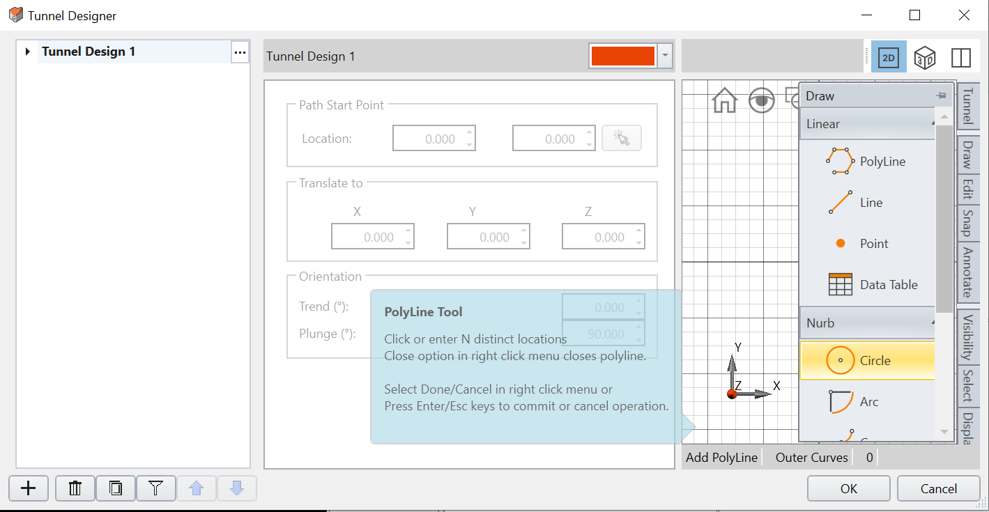
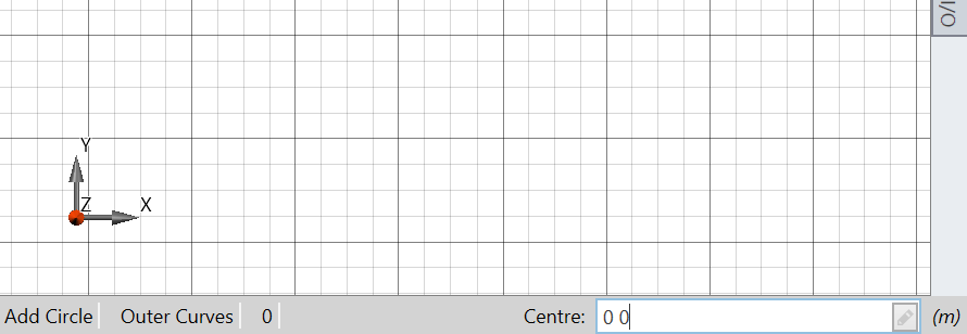
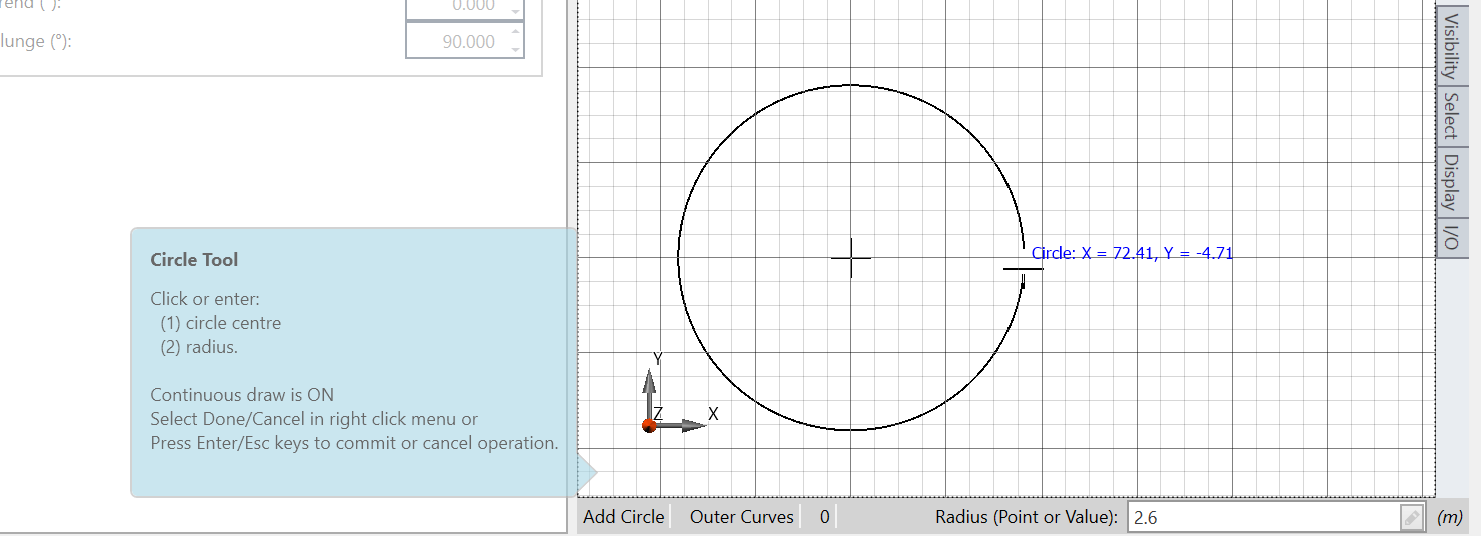
Tunnel Designer dialog box - At the bottom of the Polyline Tool, you will see a dialog prompting you to enter center coordinates. Type 0,0 for our center coordinates and press ENTER.
Polyline Tool - Enter a radius of 2.6 and press ENTER.
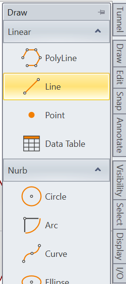
- Select: Draw > Line.
Draw dialog box - Enter the coordinates as (-2. 6, 0) and press ENTER.
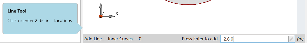
Area to enter coordinates - After adding the one point at the edge of the circle, enter (2. 6, 0) to add a second point of the line.
You should see a circular section tunnel as shown below:
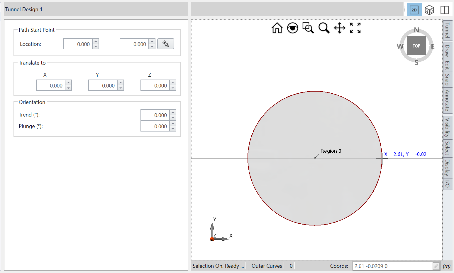
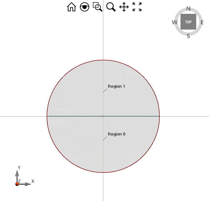
Now you will draw a line across this circular section to divide the tunnel sequence from the top section to the bottom section.
You will see the sections are automatically divided into two regions: Top = Region 1, Bottom = Region 0).
2.2 EXTRUSION OF THE TUNNEL
- In the Tunnel Design menu, select Path.
- In the Path section of the dialog, select Extrude, enter 50 m, and press Apply in the text box to see the extrusion model shown below.
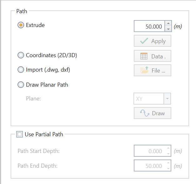
Tunnel Design dialog box
2.3 STAGED EXCAVATION
We will now move to excavation.
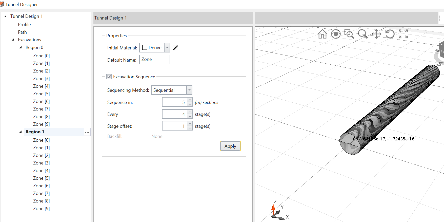
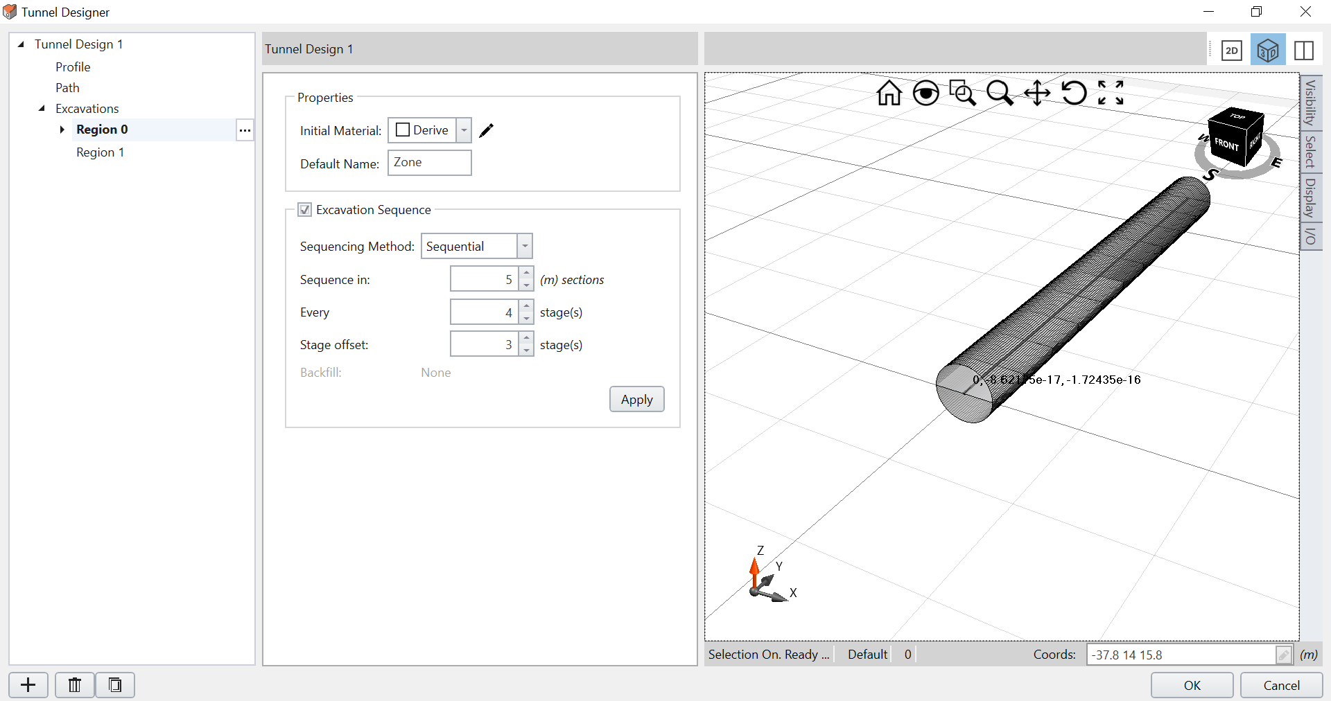
- In the Tunnel Design menu, select Excavations to see Region 0 and Region 1. This is where we will be applying staged excavations to the top and bottom regions.
- Select Region 0 and define the Excavation Sequence:
- Sequencing Method: Sequential
- Sequence in: 5 m sections
- Every: 4 stages
- Stage Offset: 3 stages.
- Leave the Properties Initial Material as Derive. When you click Apply, you will see the divided excavation sections and material staging. You can expand 'Regions' to review the thickness of each volume and material staging as shown below:
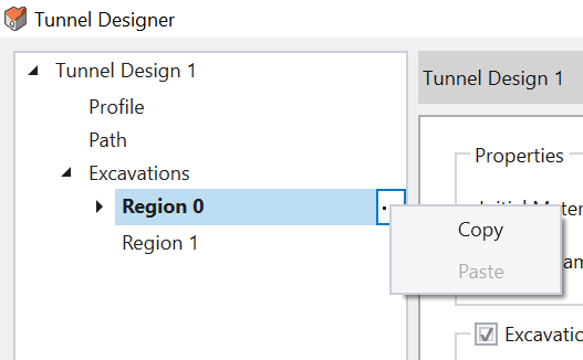
- To the right of Region 0, select … and select Copy.
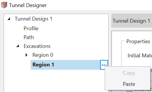
Tunnel Designer dialog box - Select Region 1 and select Paste.
Tunnel Designer dialog box - Now change the Region 1 Stage Offset setting to 1 and click Apply.
Tunnel Designer dialog box
Now, we will copy this setting from Region 0 and paste it into Region 1.
2.4 SUPPORTS
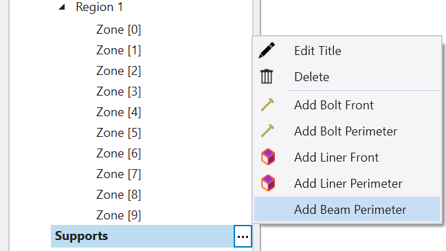
- To the right of Tunnel Design in the Tunnel Designer dialog, select … and Add Support.
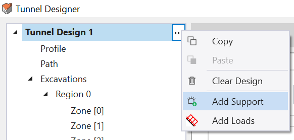
Tunnel Designer dialog- Add Support - To the right of the newly added Supports section on the Tunnel Design menu, select … and select Add Beam Perimeter.
- For Location, click Define.
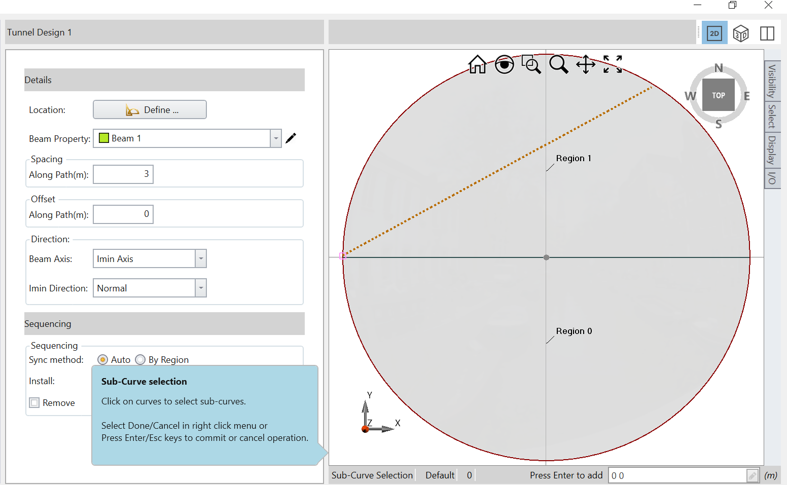
Tunnel Design dialog- under details select define - To apply the beam throughout the circumference of the tunnel, you must select three to four points along the circle. For example:
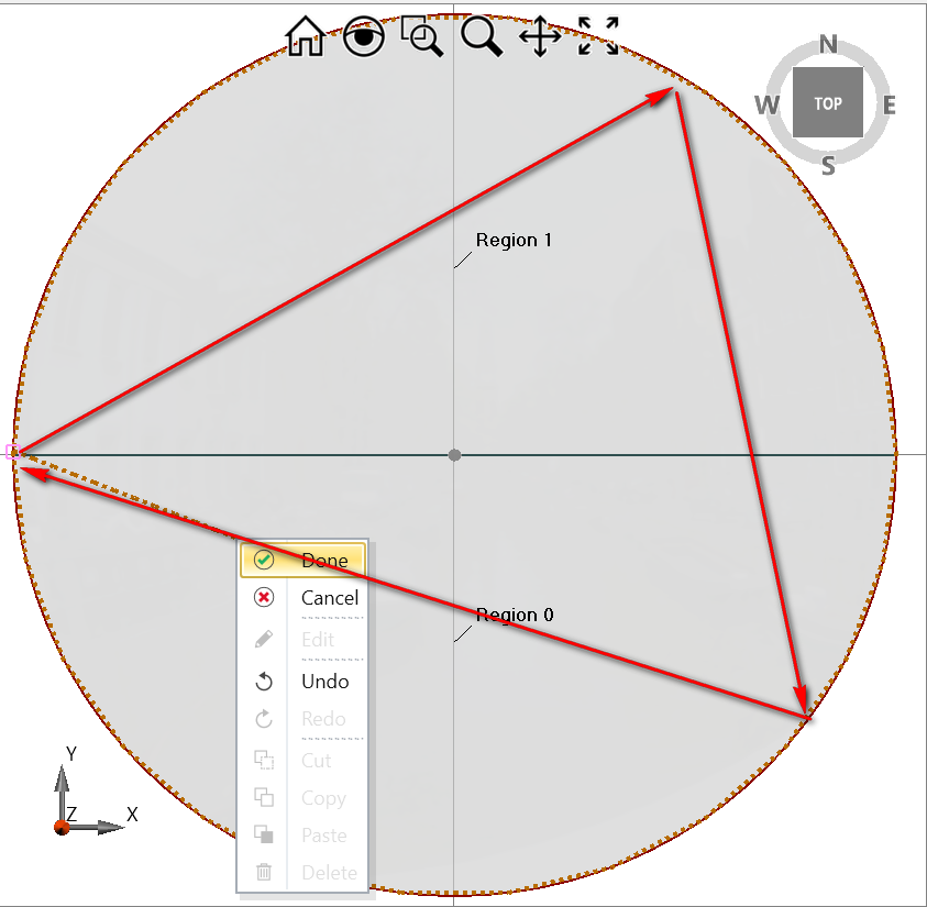
Example of applying a beam thoroughout the circumference of the tunnel - After you select the points along the circumference of the tunnel, the dotted line will show that the beam element has been added around the excavation.
- Right-click and select Done.
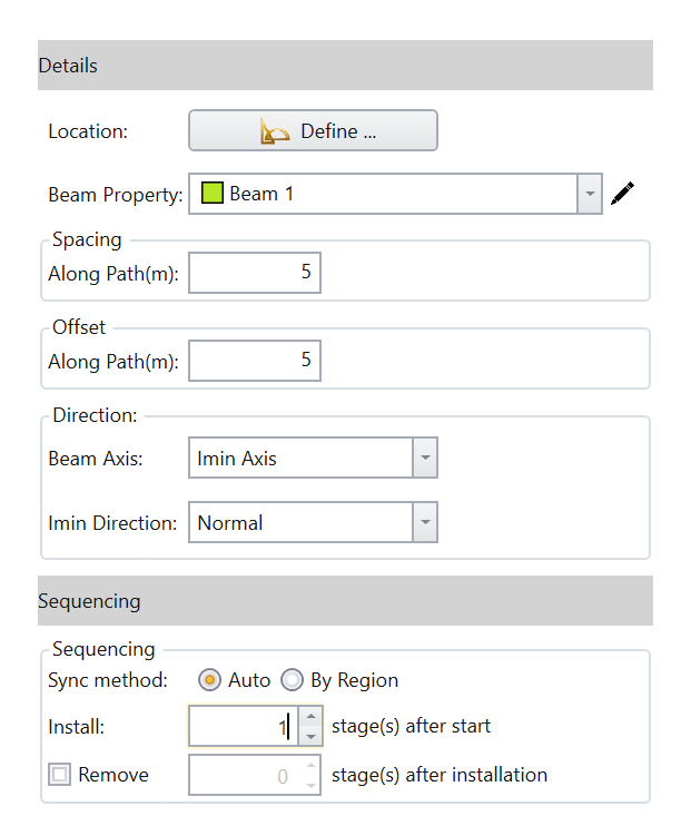
- After defining the beam location, enter the following:
You will see the cross-section view of a circle where you can define regions where the beam can be applied.
- Spacing Along Path = 5m
- Offset Along Path = 5m
- Sequencing > Install stage(s) after start = 1
The dialog should appear as below:
2.4.1 Liner on Side
Now we will apply a liner on the side.
- Select: Support > Add Liner perimeter.
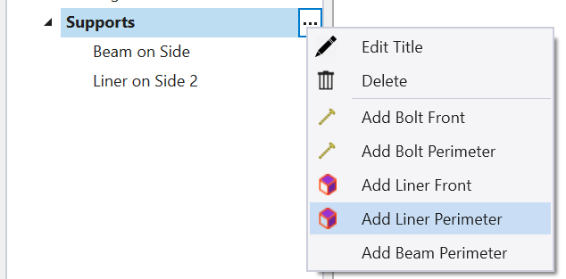
Apply Liner dialog- select support, Add Liner perimeter. - For the Location, select Define.
- Select three points along the circumference of the tunnel, right-click and select Done.
- Under Sequencing, we want to apply the liner at 12 stages after start as follows:
- Sync Method = By Region
- Region to Sync = Region 1
- Install after start = 12
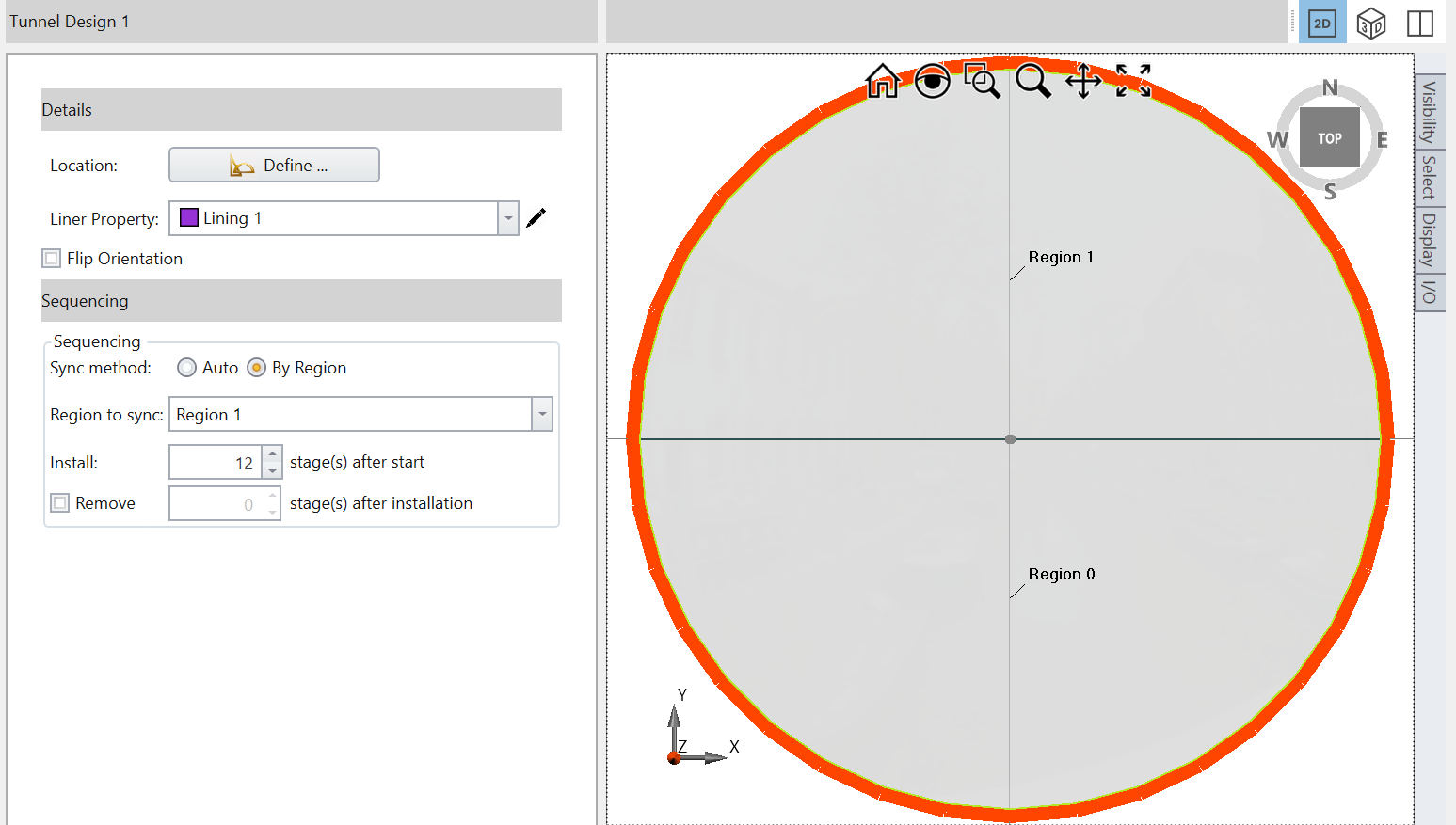
Tunnel Design 1 dialog box- Sequencing - After you have entered all the parameters, the tunnel sequence is complete. Press OK to save the tunnel design and exit the Tunnel Designer.
2.5 ADD TUNNEL DESIGN
Now we will add the tunnel design to the model.
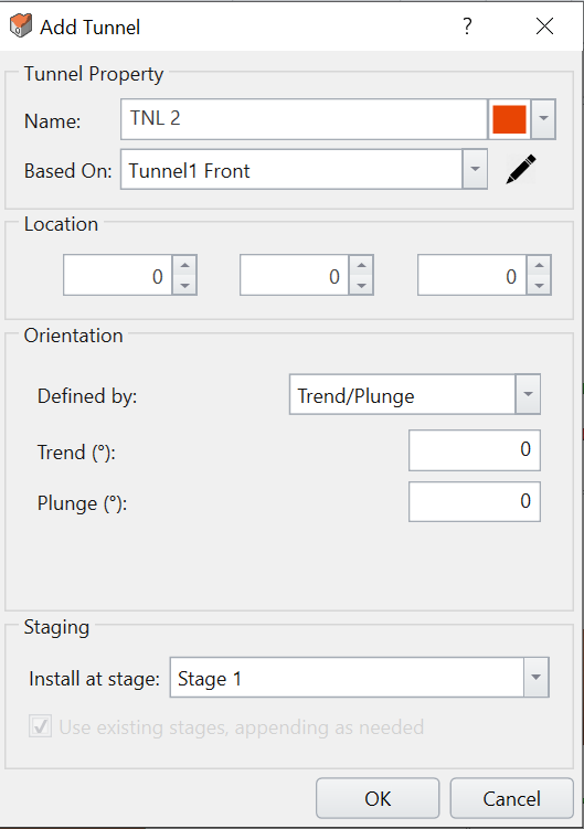
- Select: Tunnels > Add Tunnel Design

- In the Add Tunnel dialog, make sure Tunnel Design 1 is selected in the Tunnel Design dropdown.
- Enter the Location as (0, -50, 0).
- Click OK.
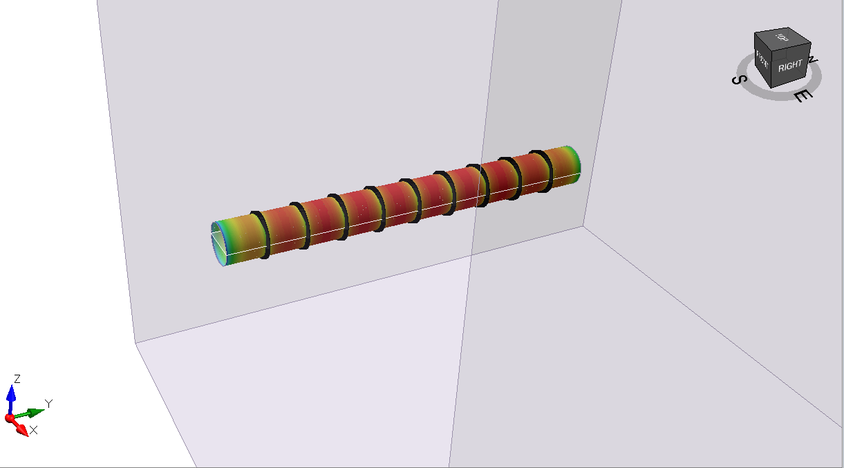
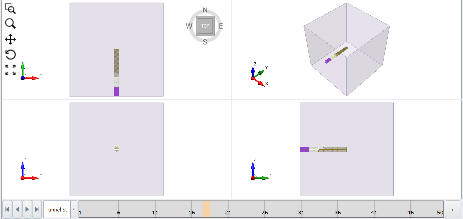
After the tunnel design is added to the model, you will see the excavation of the tunnel and application of the liner and beams as shown below (ex. Stage 16 onwards):
2.5 CONSTRAINED DIVIDE ALL
The Constrained Divide All option intersects the tunnel with the existing geometry of the RS3 model.
- Select: Tunnels > Constrained Divide All.
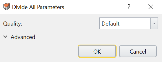
Divide All Parameters dialog box - Set Quality = Default and click OK.
3.0 Restraints
Now we will assign restraints to the modelled tunnel.
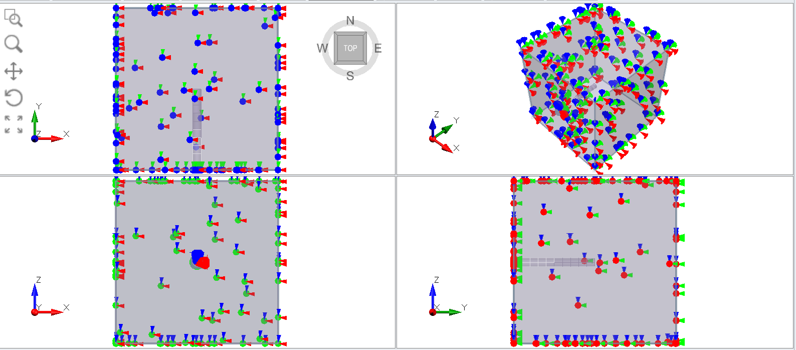
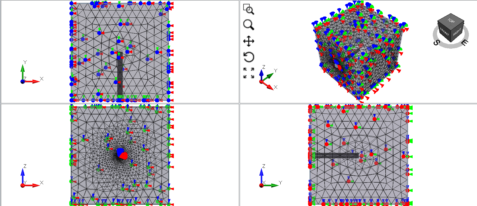
- Select: Restraints > Auto Restraints
You should see the results below.
4.0 Mesh
- Select: Mesh > Mesh Settings.
- Keep the default values and click Mesh.
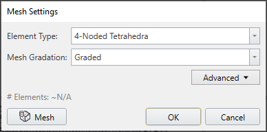
The meshed model should look as follows.
5.0 Compute
- Select: Compute > Compute

6.0 Results
- To the right of the model, set the Legend to Solids and Total Displacement.
We will first turn on the excavation contour plot.
- Select: Interpret > Show excavation contour

- Select Stage 50 (last stage) to see the displacement contour of the excavation.
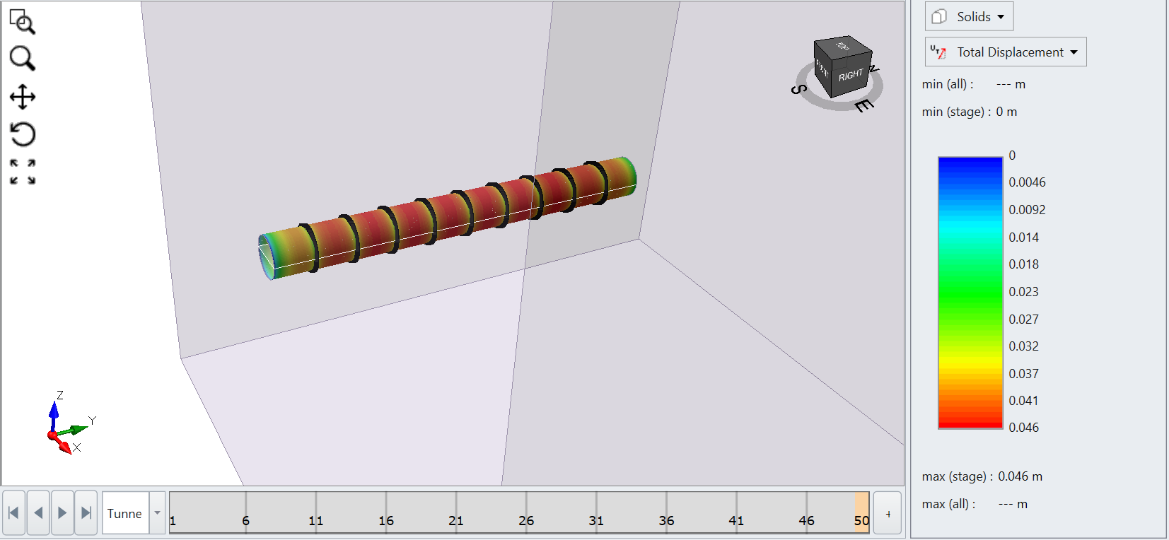
Displacement contour - Select Solids > Mean effective stress to see the mean effective stress around the excavation region as shown below:
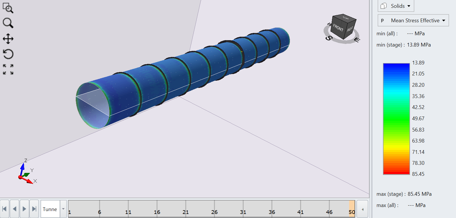
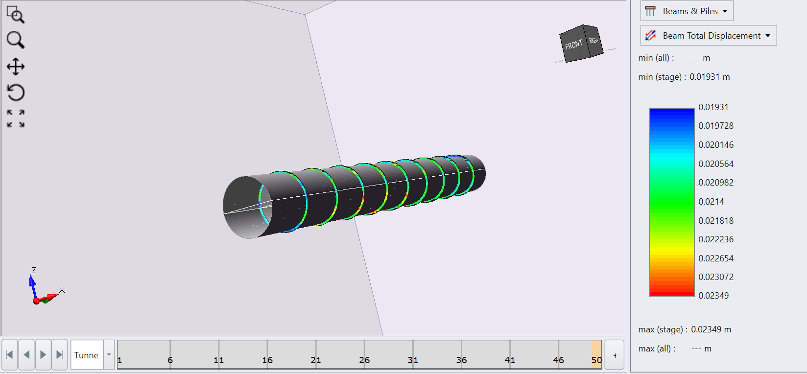
Mean effective stress around the excavation region - If you select Beams > Total Beam displacement, you will see the total displacement of the beams as shown below:
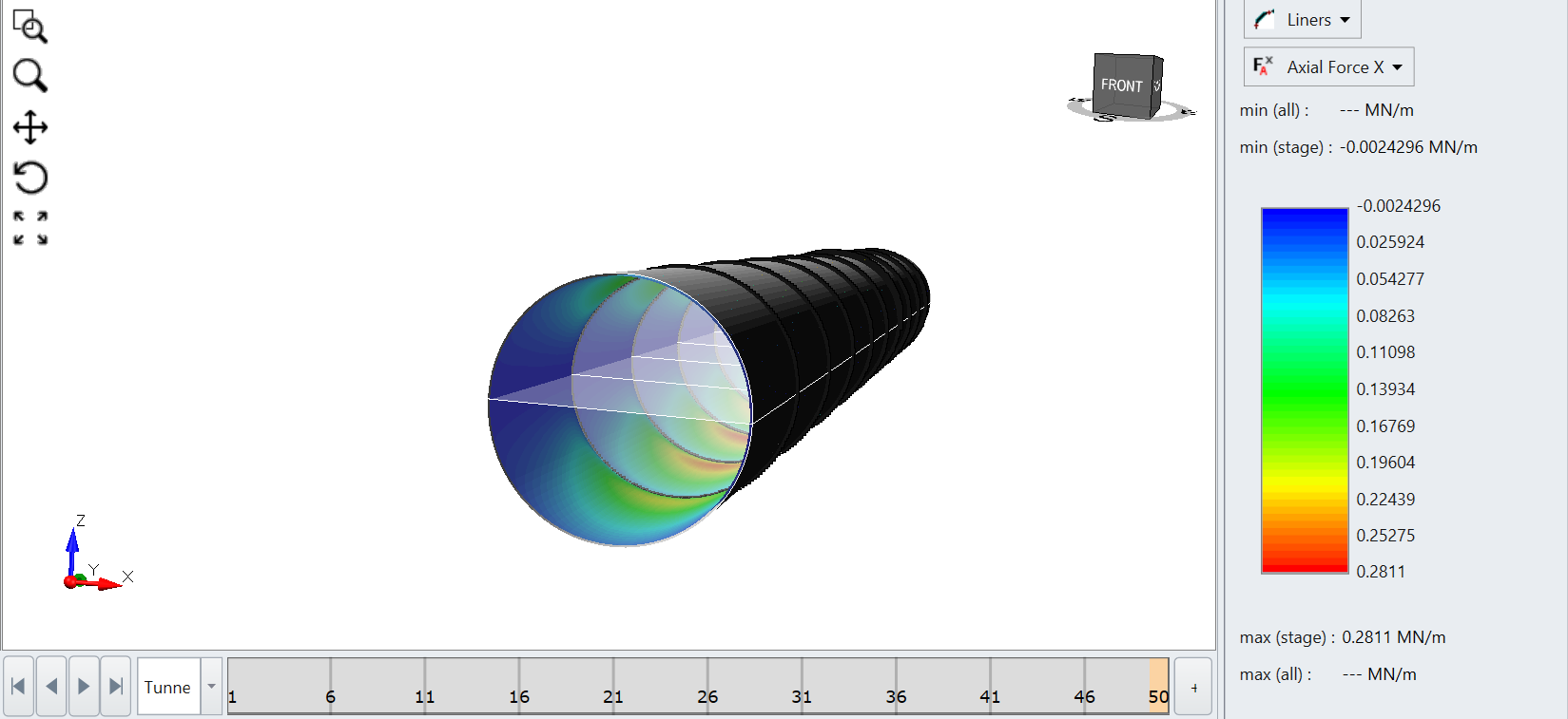
You can also see the interaction of the liner due to excavation by plotting the force/moment of the liner at the end of the stage as shown below. Hide the external box in visibility tree to see a better contour.
Axial force X for liner:
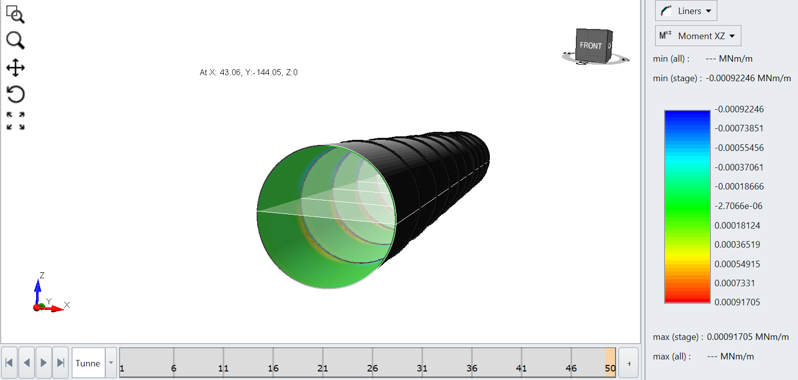
Moment along XZ plane:
There are many other options which you can navigate and plot for beams, liners, and solids.
This concludes the tutorial.