Trench with Piles and Struts
1.0 Introduction
In this tutorial, RS2 is used to simulate the excavation of a trench into a sloped embankment. The trench is supported by soldier piles and struts. The model was built in five stages:
- Bring soil layers to equilibrium
- Install a pile on the high side of the trench
- Excavate the first section of the trench and lower the water table
- Install a pile on the low side of the trench and install a strut between the two sides
- Excavate the final section of the trench and lower the water table
2.0 Constructing the Model
- Select: File > Recent Folders > Tutorial Folder
- Open the starting file Trenches with Piles and Struts (Initial)
Begin by importing a file in which geometry, materials, and boundary conditions have already been assigned.
2.1 Project Settings
- Select: Analysis > Project Settings

- In the Stages tab, set the Number of Stages to 5.
- Click OK to close the dialog.
2.2 Automatic Liner Removal Option
- Select: Support > Automatic Liner Removal to make sure the automatic liner removal option is off.
To model strut support in RS2, the Automatic Liner Removal option must be turned OFF. This allows the excavation of the material on both sides of the strut (liner), without automatically removing the support (this will be done in Stage 5). The initial file should have the Automatic Liner removal option turned off. (When the option is ON a checkmark appears beside the menu option, when it is OFF, no checkmark appears).
2.3 Stage 1: Initial Conditions
![]()
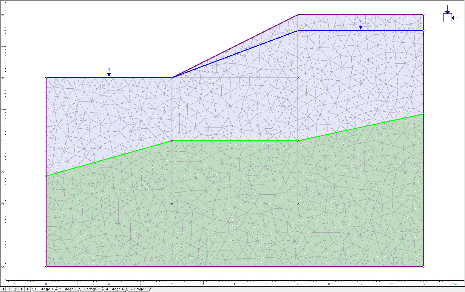
For Stage 1, add a piezometric line to delineate the water table.
- Select: Boundaries > Add Piezometric Line

- Enter the following coordinates: (0, 6), (4, 6), (8, 7.5), (12, 7.5)
- Hit Enter to finish entering the points.
- In the Assign Piezometric Line to Materials dialog, click on the checkboxes beside Material 1 and Material 2 as shown.
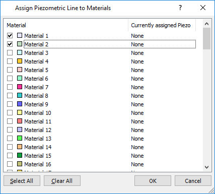
- Click OK. The model for Stage 1 should now look like this:
2.4 Stage 2: Install Pile Support

- Select the Stage 2 tab.
To add a pile to the right side of the trench (to be created):
- Select: Properties > Define Liners

- Change the name of Liner 1 to Pile.
- Change the thickness to 0.2 m as shown.
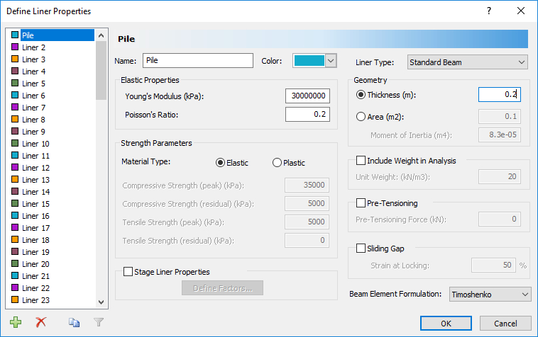
- Click OK to close the dialog.
To install the liner:
- Select: Support > Add Liner

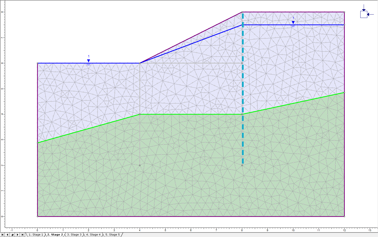
- In the “Add Liner” dialog,ensure that the Liner Property is Pile and Install at stage is set to 2. Click OK.
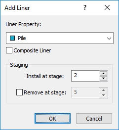
- Now select the three-stage boundaries to the right of the future trench at x = 8 m. Hit Enter to finish selecting boundary segments.
The model should look like this for Stage 2:
2.5 Stage 3: Excavate Soil and Lower Piezometric Line
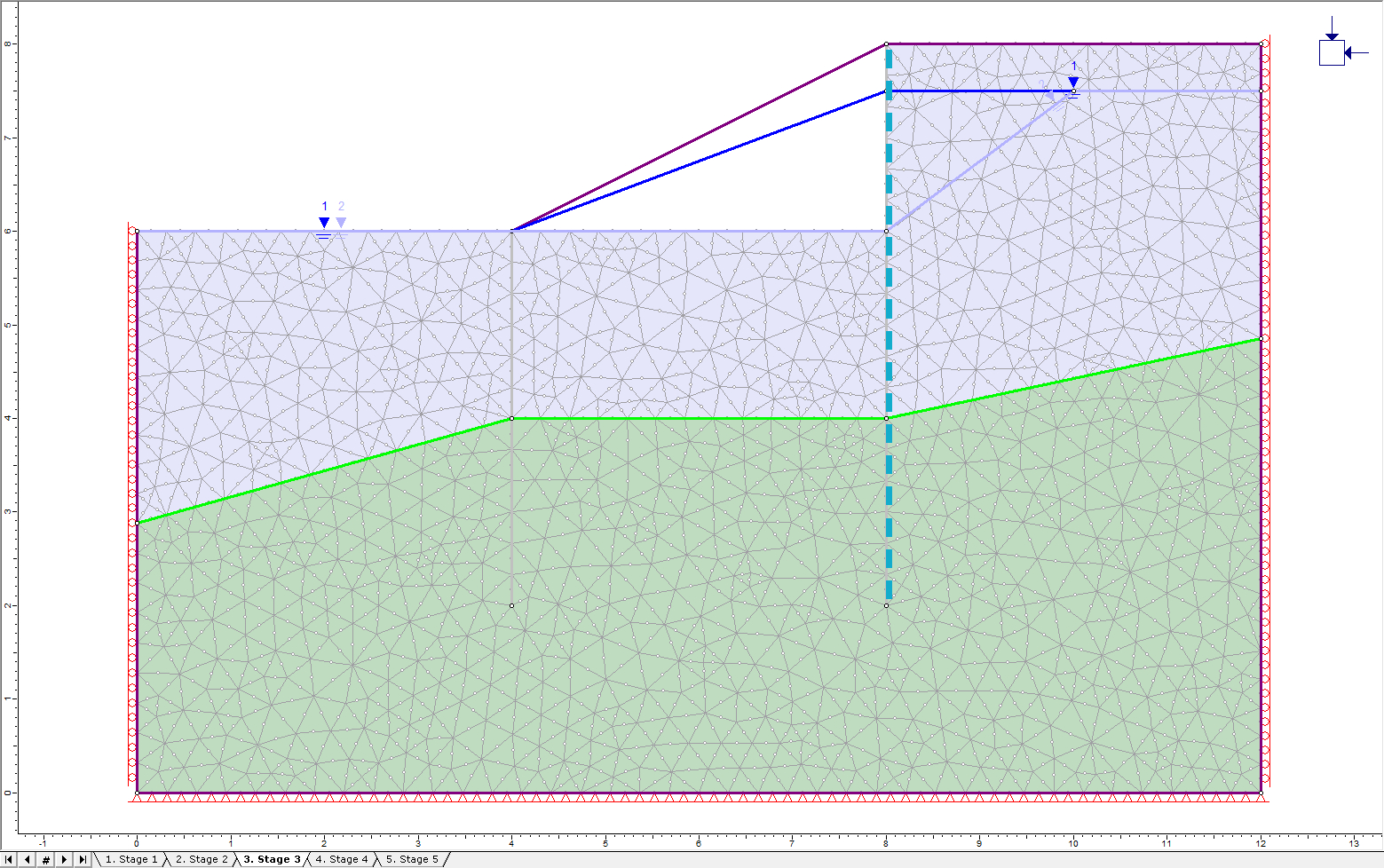
Click on the Stage 3 tab. In this stage, the first part of the trench will be excavated, and the water table lowered.
- Select: Properties > Assign Properties
- Make sure that Materials is selected from the drop-down menu at the top.
- Click on Excavate:
- Click in the triangular section at the top-middle of the model to excavate the first part of the trench. Close the Assign dialog.
- Select the Support workflow tab
A new piezo line that runs below the new surface must be created:
- Select: Boundaries > Add Piezometric Line
- Enter the following points: (0, 6), (8, 6), (10, 7.5), (12, 7.5). Press Enter.
- In the “Assign Piezometric Line to Materials” dialog, do not check any of the materials.
- The materials need to be assigned different piezo lines at different stages (will be assigned at Stage 5). Click OK to close the dialog.
Both piezo 1 and piezo 2 are now plotted. The model for Stage 3 should look like this:
2.6 Stage 4: Install Second Pile and Strut Support
Click on the Stage 4 tab. The properties of the pile have already been set up, it is ready for installation:
- Select: Support > Add Liner
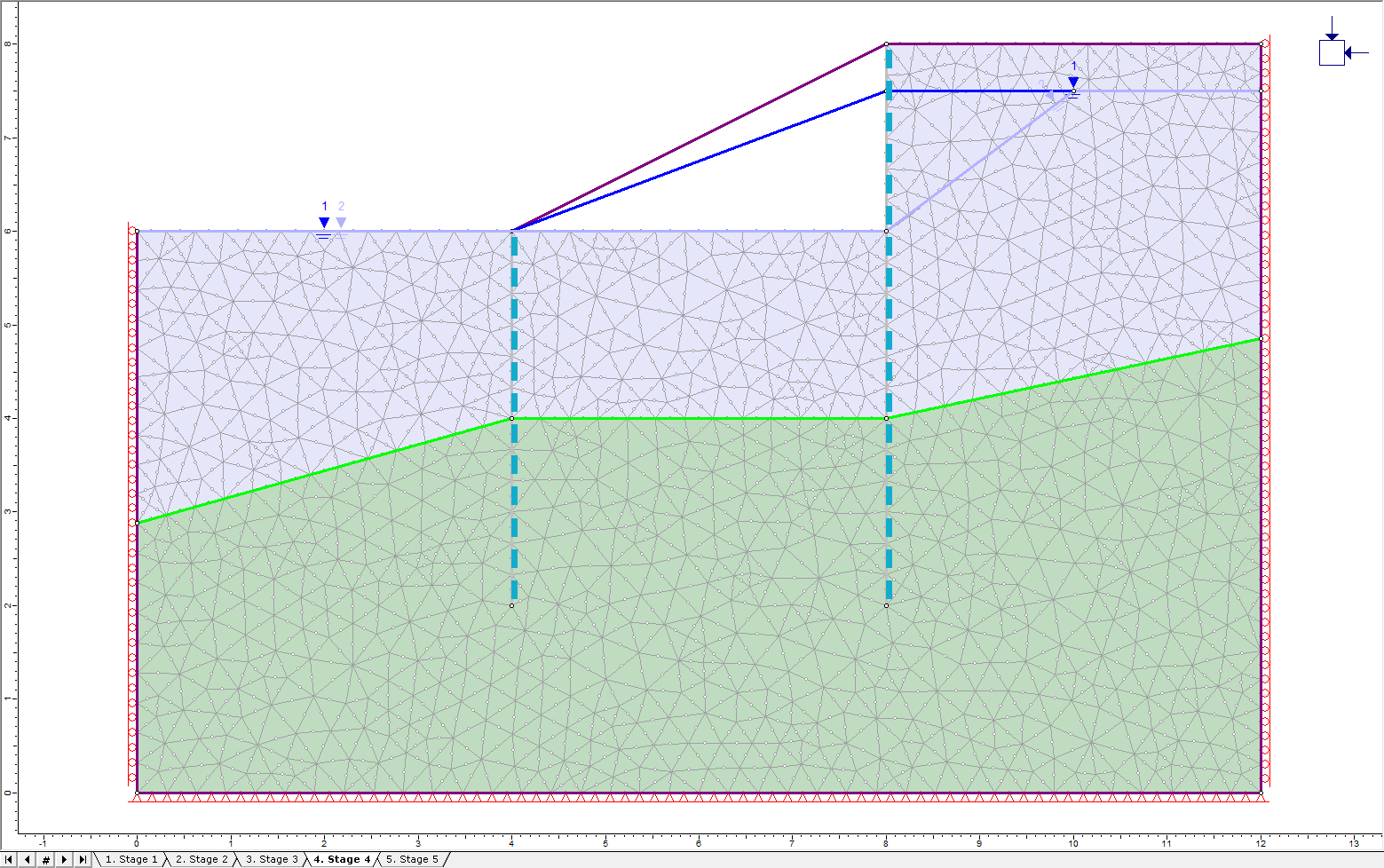
- Ensure the Liner Property is Pile and Install at Stage is set to 4. Click OK.
- Now select the stage boundaries to the left of the trench at x = 4 m and press Enter
To install a strut between the two piles to support the excavation that will occur in Stage 5:
- Select: Properties > Define Liners
- Click on the tab for Liner 2. Change the name to Strut.
- Under Geometry, turn on the Area option. Change the Area to 0.2 m2 and the Moment of Inertia to 1e-20 m4 as shown.
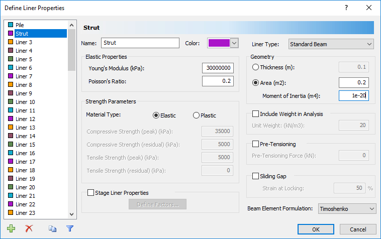
Setting a very low moment of inertia ensures that the beam will experience no flexure or torsion – only axial forces.
- Click OK.
- Now add the strut by selecting the Add Liner button.
- In the Add Liner dialog, select Strut from the drop-down menu for the Liner Property. Ensure that the Install at Stage option is set to 4. Click OK.
- Now click on the boundary segment at the top of the soil between the two piles. Right-click and choose Done Selection.
The model should now look like this:

TIP: To hide the piezo line before installing the strut, click on the "eye" icon in the Model Items column of the Property Viewer on the left side of the screen. It is necessary to hide the piezo lines to access the liner strut information by right-clicking on it since the strut is “underneath” piezo line 2.
2.7 Stage 5: Excavate Soil and Lower Piezometric Line
Click on the tab to show Stage 5. In this stage, the remainder of the trench will be excavated, and an additional piezo line added.
- Select: Properties > Assign Properties

- Click the Excavate button in the dialog and then click inside the lower section of the trench between the piles and just below the strut. Close the Assign dialog.
Add another piezo line below the new soil surface:
- Select: Boundaries > Add Piezometric Line
- Enter the following points: (0, 6), (3, 6), (4, 4), (8, 4), (9, 6), (10.5, 7), (12, 7.5)
- Press Enter to finish entering points.
- In the resulting dialog, do not select any materials and click OK.
It is now time to assign the piezo lines to the correct stages.
- Select: Properties > Define Hydraulic

- Select the Stage Factors tab. Check the box for Stage Hydraulic Properties.
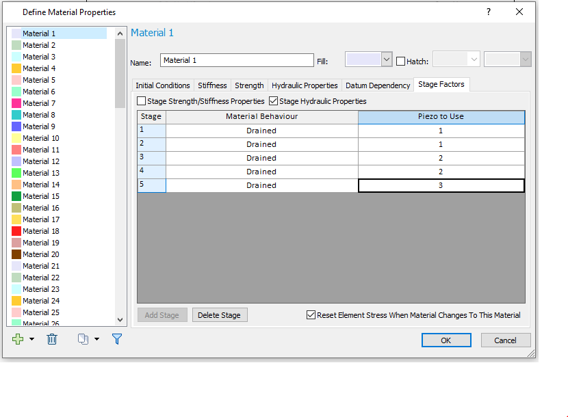
- For Material 1, turn on the option for Stage Hydraulic Properties. Click Add Stage 3 times to get a total number of 5 stages.
- For Stage 1, set the Piezo # to 1.
- For Stage 2, set the Piezo # to 1.
- For Stage 3 set the Piezo # to 2.
- For Stage 4 set the Piezo # to 2.
- For Stage 5 set the Piezo # to 3. Set the Material Behaviour as Drained for all stages. The dialog should now look like this:
- Material 2 is affected by the piezo lines in the same way as Material 1. Therefore, select Material 2 and repeat the above steps to stage the piezo lines.
3 piezo lines will still appear on the model. To only see the piezo line for the relevant stage:
- Select: Groundwater > View Piezos by Stage.
The model should look like this for Stage 5:
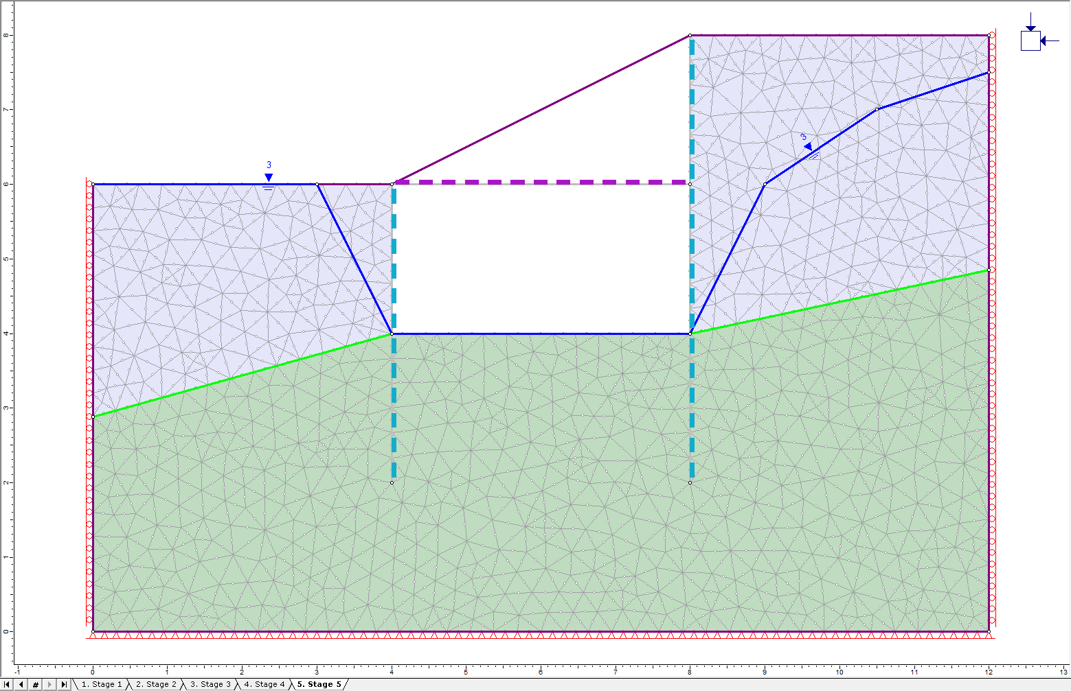
Click through the other stages to ensure that the piezo lines are where they should be. The model definition is now complete.
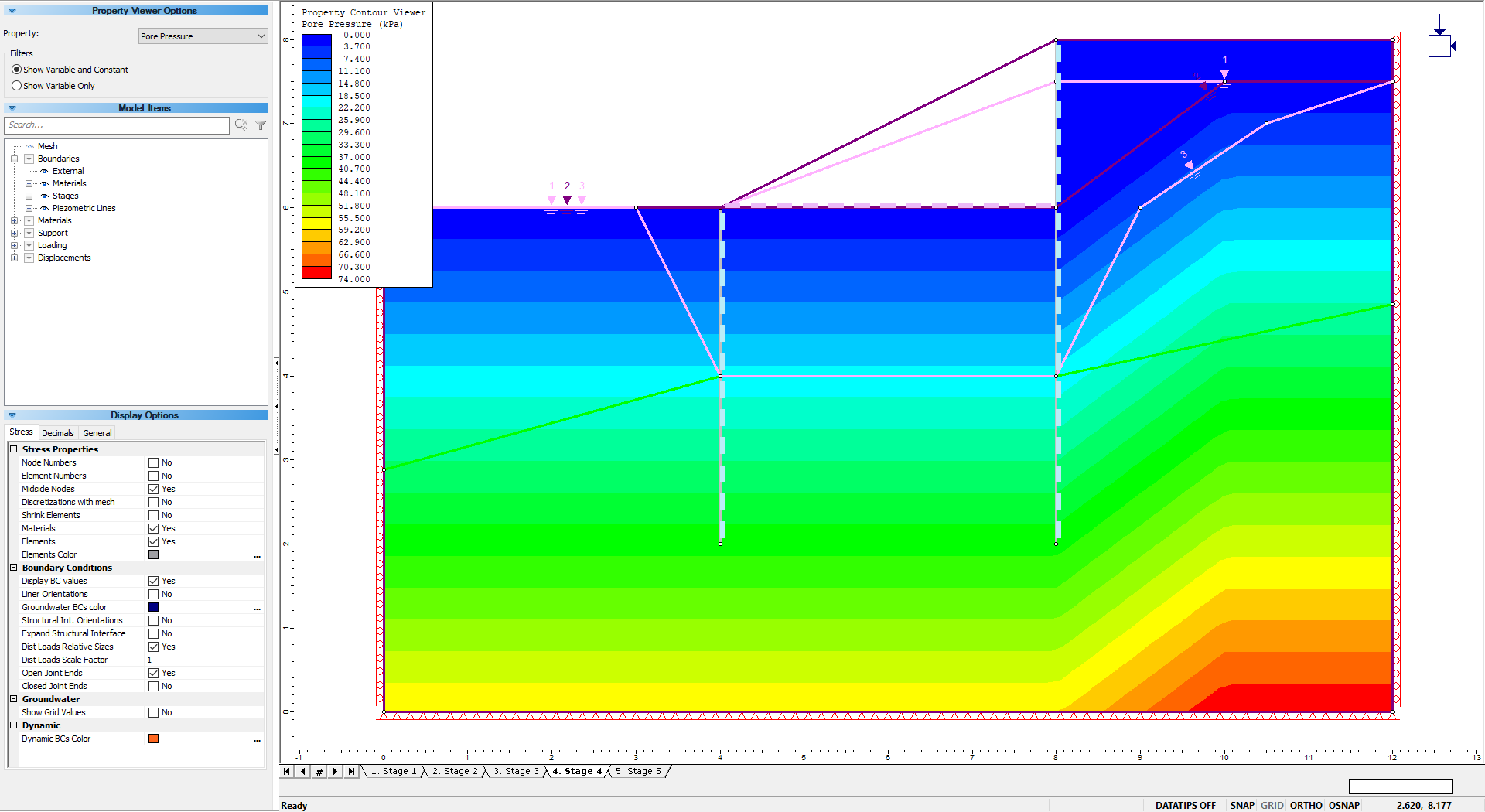
Before computing the model, use the Property Viewer to preview the pore pressure by stage.
- Select Property Viewer
 from the toolbar.
Click through the stages to view the impact of the excavation and piezometric lines on pore pressure.
- Save the model with a different name by selecting File > Save As in the menu.
3.0 Compute
- Select: Analysis > Compute

4.0 Results and Discussion
- Select: Analysis > Interpret

The maximum stresses for Stage 1 will be displayed.
- Select: Total Displacement from the drop-down menu in the toolbar to view contours for total displacement
- Select: Display Deformed Boundaries
 in the toolbar
The plot should look like this:
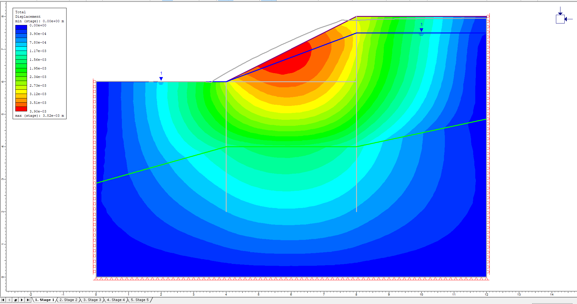
Some deformation has already occurred. Pressing the Display Yielded Elements button shows that significant failure has occurred at the top of the slope.
Turn off the yielded elements.
- Select: Stage 2 tab.
The addition of the soldier pile has no effect until the trench is excavated.
- Select: Stage 3 tab.
- Significant displacement is visible at the right side and bottom of the trench.
- The pile appears to be bending due to the weight of the soil it is holding back.
- Verify this by right clicking on the liner.
- Select: Show Values > Bending Moment.
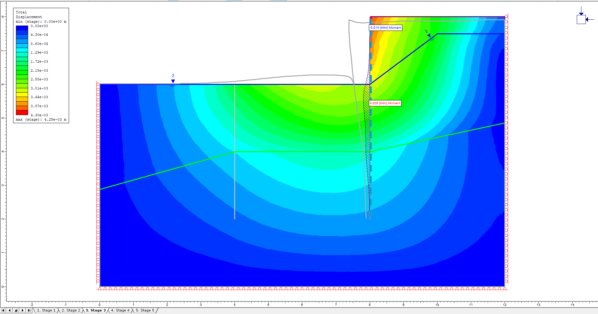
The plot shows positive bending moments just below the surface of the trench.
- Select: Stage 4 tab.
Very little difference exists as the other pile and the strut are added.
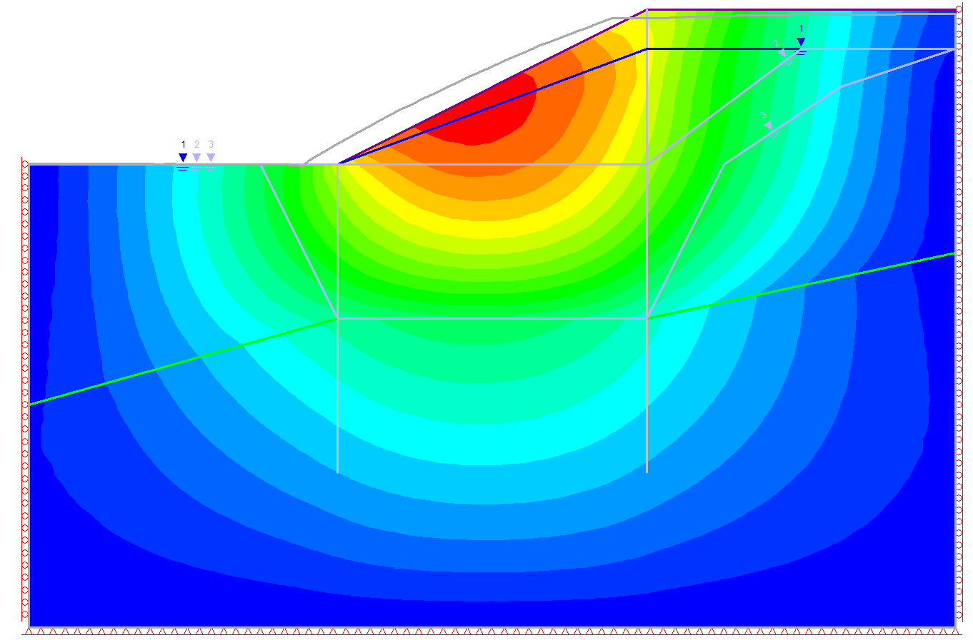
- Select: Stage 5 tab.
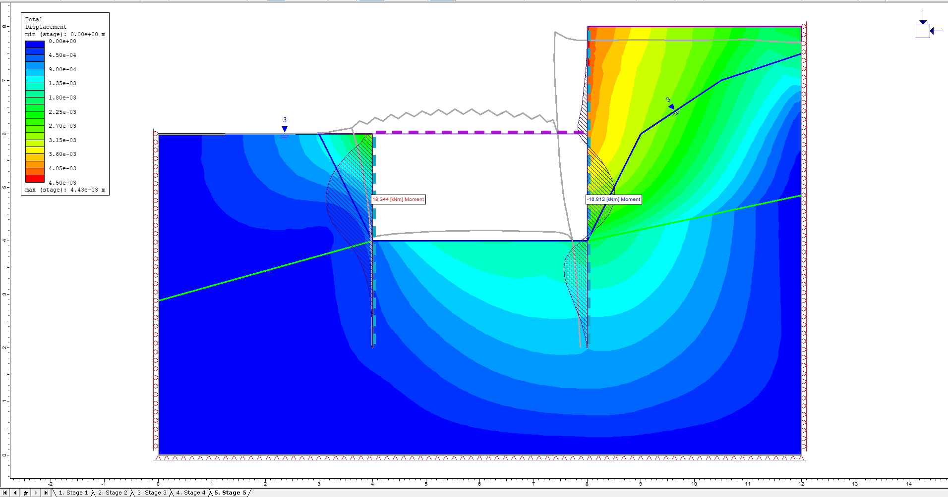
Even larger bending moments are now visible in the two soldier piles. Note the moment change from positive to negative in the right pile as it passes the strut, showing how the pile bends around the supporting strut. It is also interesting to observe how the left side of the trench is deformed to the left as it is being pushed by the strut.
The strut shows no moment because its moment of inertia was set to a very small value to prevent bending and twisting.
To observe the effect of the strut:
- Select Graph > Graph Liner Data. Ensure that the Vertical Axis is set to Axial Force as shown.
- Select Plot in the Graph Liner Data dialog.
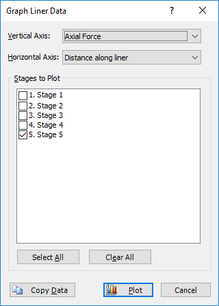
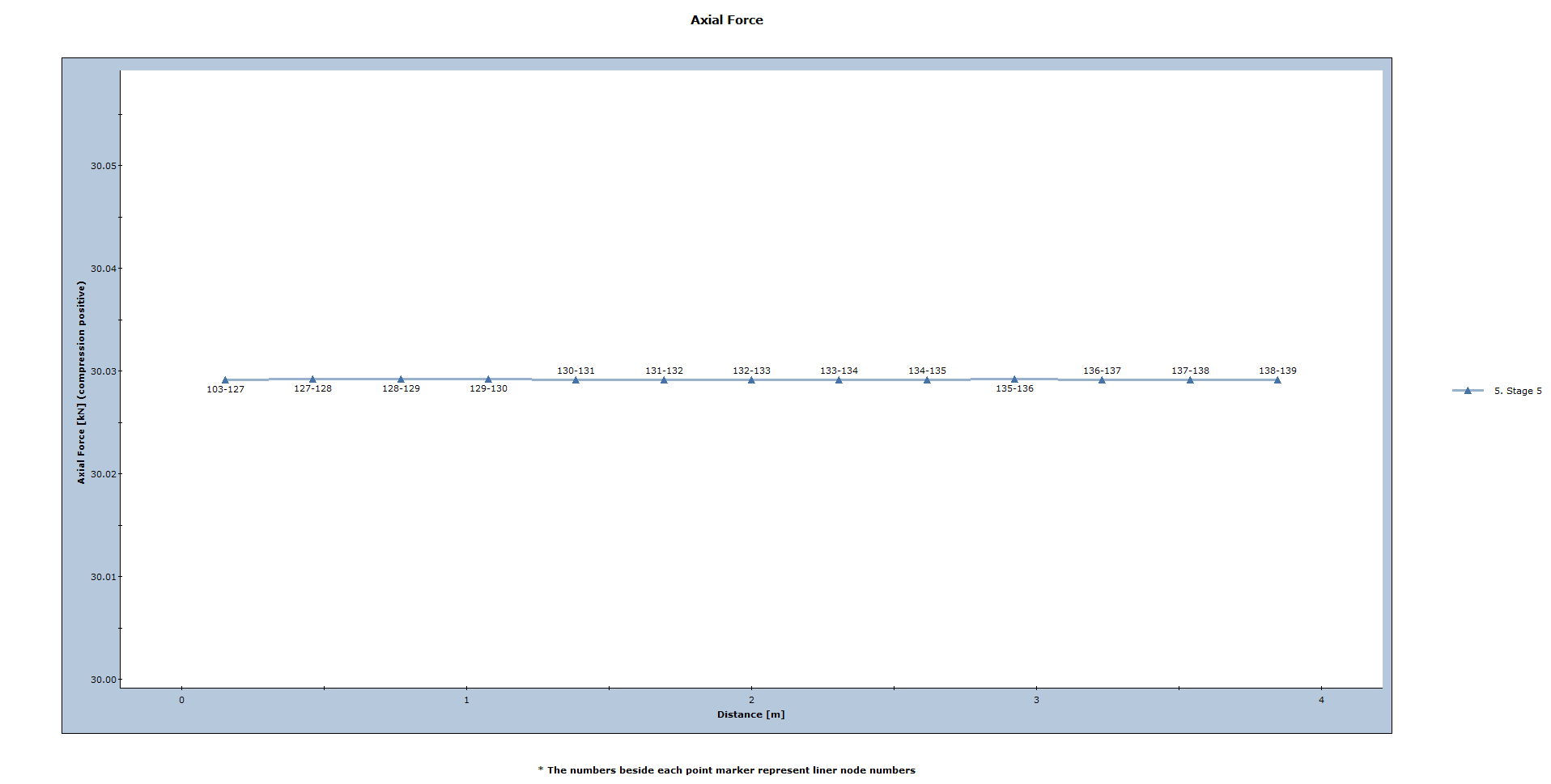
The plot shows the constant positive axial force experienced by the strut, clearly indicating that it is providing support to the excavation.
5.0 Additional Exercises
- Try running the model again without the strut. This should show significantly more deformation and failure on the right side of the trench as shown below. Notice there is little deformation on the left side since the left side is not providing any support to the failing right side via the strut.
- Try using structural interfaces for the soldier piles instead of liners. The structural interfaces should be composed of a Pile sandwiched between two joints. Set the joint Slip Criterion to Mohr-Coulomb and there should be slippage between the piles and the soil.
This concludes the Trench with Piles and Struts Tutorial.