Set Boundary Conditions
If the Groundwater Method = Steady State FEA or Transient FEA in Project Settings, then the groundwater (hydraulic) boundary conditions are specified with the Set Boundary Conditions option in the Groundwater menu.
NOTE: before boundary conditions can be assigned, the finite element mesh must exist. See the Mesh Overview topic for information. If the mesh does not exist, the Set Boundary Conditions option will NOT be enabled.
To define groundwater boundary conditions:
- After the mesh has been generated, select the Set Boundary Conditions
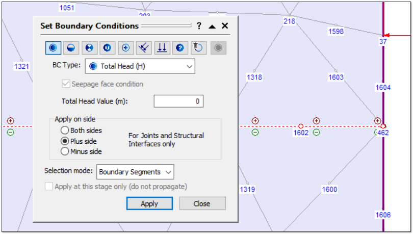
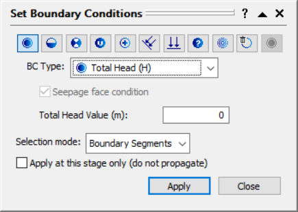
 option from the toolbar or the Groundwater menu. You will see the Set Boundary conditions dialog.
 - Boundary Condition Type - in the Set Boundary Conditions dialog, select a Boundary Condition Type that you would like to apply. You can select from the drop-list, or use the icons at the top of the dialog. The options are:
- Total Head (H)
- Zero Pressure (P=0)
- Nodal Flow Rate (Q)
- Normal Infiltration (q)
- Vertical Infiltration (q)
- Unknown (P=0 or Q=0)
- None / Remove BC
- Pressure Head
- Pore Pressure
- Constant
- Value - if you are applying Total Head, Nodal Flow Rate, or Infiltration boundary conditions, then you must enter a value in the edit box. If you are applying any other boundary condition, then a value is not applicable.
- Seepage Face - if you are applying Nodal Flow Rate or Infiltration boundary conditions, then you can also specify a Seepage Face condition by selecting the check box. See below for more information.
- Selection Mode - boundary conditions can be applied by selecting boundary line segments, vertices or nodes. Select the desired method from the Selection Mode list. NOTE:
- Infiltration boundary conditions can only be applied to line segments and not to individual nodes.
- Nodal Flow Rate conditions can only be applied to vertices or nodes, not to line segments.
- For all other boundary conditions, you may choose any Selection Mode (segment, vertex or node).
- Use the mouse to select the boundary segments, vertices or nodes. When you are finished selecting, press Enter or right-click and select Done Selection, or select the Apply button in the dialog. The boundary condition you have selected in Step 2 will be applied to all selected segments, vertices or nodes.
- Repeat steps 2 to 6, until all of the boundary conditions are applied.
- When you are finished, you can select the Close button in the dialog, or right click the mouse and select Cancel from the popup menu, or press Escape.
Groundwater Boundary Conditions dialog
Constant Boundary Conditions
Applying a constant groundwater boundary condition tells the RS2 program to keep pressure the same as in the previous stage.
Note: If the constant groundwater boundary condition is applied, the nodes will appear on model in stage 2 at the earliest, even if applied to stage 1.
Infiltration Boundary Conditions
Unlike other groundwater boundary conditions, Infiltration boundary conditions can only be applied to line segments of the model, and NOT to individual nodes of the mesh. This is because Infiltration is, by definition, specified over an AREA, and not at POINT locations.
Notice that the units of Infiltration are m / sec (in metric units). This is because Infiltration represents a VOLUME of fluid, entering (or leaving), an AREA of a boundary. Therefore, the units are ( m3 / sec ) / (m2) = ( m / sec). NOTE that these units consider the third dimension of the model (the out-of-plane direction, perpendicular to the 2D view of the model).
Infiltration can be specified in the Vertical direction, or Normal to boundaries. In most cases you will be specifying a Vertical Infiltration (e.g. rainfall on a slope). Normal Infiltration may be required in some cases (for example, if you need to specify Infiltration on a vertical boundary).
Unknown Boundary Conditions- Vacuum Pressure
When Unknown (P=0 or Q=0), the option for defining Vacuum Pressure is available. Checking the box next to Vacuum Pressure (MPa) allows the user to enter a value if the vacuum pressure is know. This will change the P value from 0 to the value entered. This option is useful in cases with vacuum consolidation with a known vacuum.
None (Remove BC)
The None (Remove BC) option is used to remove or delete a hydraulic boundary condition.
Seepage Face Condition
For Infiltration and Nodal Flow Rate boundary conditions you can specify that the boundary is a seepage face. This ensures that the total head calculated at a node does not exceed the elevation head of the node. To enforce the Seepage Face condition, select the check box.
Min / Max pressure: minimum/maximum value of pressure that is allowed to be at the location where infiltration was applied. Please note that for transient infiltration, for the time that infiltration value is zero, the min value will not be applied. Using the value larger than zero for max pressure also required user to assign ponded water load at the infiltration location to avoid unrealistic behavior.
Selection Mode
The Selection Mode option allows the user to choose the method for applying the boundary conditions. The following Selection Modes are available.
- Boundary Segments – boundary conditions are applied to entire boundary segments (i.e. only boundary segments can be selected, and boundary conditions will be applied to all nodes of the selected segments). When a user select a joint segment, they will be able to select which side of the joint to be restrained.
- Boundary Vertices– only vertices of boundaries can be selected (i.e. the vertices which define the boundary geometry).
- Boundary Nodes – any node(s) along a boundary can be selected.
NOTE: groundwater boundary conditions are actually always applied to nodes of the mesh, regardless of the Selection Mode (i.e. even if the Selection Mode is Boundary Segments or Boundary Vertices, the boundary conditions are ultimately applied to the mesh nodes along the boundary. This includes Infiltration boundary conditions.)
Staging Groundwater Boundary Conditions
In a multi-stage model, you can stage the groundwater boundary conditions if necessary (i.e. modify the boundary conditions as staging progresses). To stage the groundwater boundary conditions:
- Before you apply a boundary condition, first select the desired Stage Tab.
- Then apply the boundary condition to the desired boundaries, vertices or nodes.
- The boundary condition will be applied at the current stage, and will propagate to all subsequent stages. Stages before the current stage will not be affected.
- This allows you to change the type of boundary condition, or the value of the boundary condition, at different stages (e.g. you could change the value of Total Head, Infiltration or Nodal Flow Rate at different stages).
Note: If your groundwater boundary conditions do not change with staging, then you should apply all boundary conditions at the first stage of the model.
Apply at this stage only
If you want to apply a boundary condition at a selected stage, without propagating to subsequent stages, then select the Apply at this stage only check box in the Set Boundary Conditions dialog, before you apply the boundary condition. This will apply the boundary condition to the currently selected stage only, without propagating to subsequent stages.
Right Click Shortcut
Groundwater boundary conditions can also be applied using the following right-click shortcut:
- Right-click the mouse directly on a boundary line segment or vertex.
- The segment or vertex will be highlighted and a popup menu will appear. Select an option from the popup menu.
- If the option does not require a value (i.e. Zero Pressure or Unknown), then the boundary condition will be assigned immediately to the segment or vertex.
- If the option requires a value (i.e. Total Head, Infiltration, or Nodal Flow Rate), then you must enter the value in the prompt line (at the bottom right of the screen), and select Enter. The boundary condition will be applied when you select Enter.
Note:
- In order to use the right-click shortcut, the finite element mesh must exist.
- If the Restraint boundary conditions are displayed, then you must first select the Show Boundary Conditions option in the Groundwater menu or the toolbar, to switch the display from restraints to groundwater boundary conditions, before you can use the right-click shortcut.