1 - RocSupport Quick Start
1.0 Introduction
This tutorial is a simple introductory tutorial that helps you become familiar with the basic modeling and data interpretation features of RocSupport. RocSupport is an easy-to-use software tool for estimating deformation in circular or near circular excavations in weak rock and visualizing the tunnel interaction with various support systems. Given the tunnel radius, in-situ stress conditions, rock and support parameters, a ground reaction curve, and a support reaction curve are calculated. The intersection of these curves determines a factor of safety for the support system.
Topics Covered in this Tutorial:
- Duncan Fama Solution Method
- Deterministic Analysis
- Tunnel and Rock Parameters
- Adding Support
- Info Viewer
Finished Product:
The finished product of this tutorial can be found in the Tutorial 01 Quick Start.rsp file, located in the Examples > Tutorials folder in your RocSupport installation folder.
1.1 Problem Description
This tutorial will demonstrate how to use the Duncan Fama solution method to determine the Ground Reaction Curve. The tunnel will first be analyzed without support. Then support will be added, and a factor of safety for the support determined. Analysis will be Deterministic (all parameters assumed to be exactly known).
The model used in the analysis is a 12 meter diameter tunnel constructed at a depth of 60 meters in a rock mass whose strength is defined by the Hoek-Brown criterion with an intact rock strength σci = 7 MPa, constant mi = 10, and a Geological Strength Index = 15.
2.0 Model Creation
If you have not already done so, run RocSupport by double-clicking on the RocSupport icon in your installation folder or by selecting Programs > Rocscience > RocSupport > RocSupport on the Start menu. If the RocSupport application window is not already maximized, maximize it now, so that the full screen is available for viewing the model.
To begin creating the model:
- Select File > New
 in the menu or click on the icon in the toolbar.
2.1 GROUND REACTION VIEW
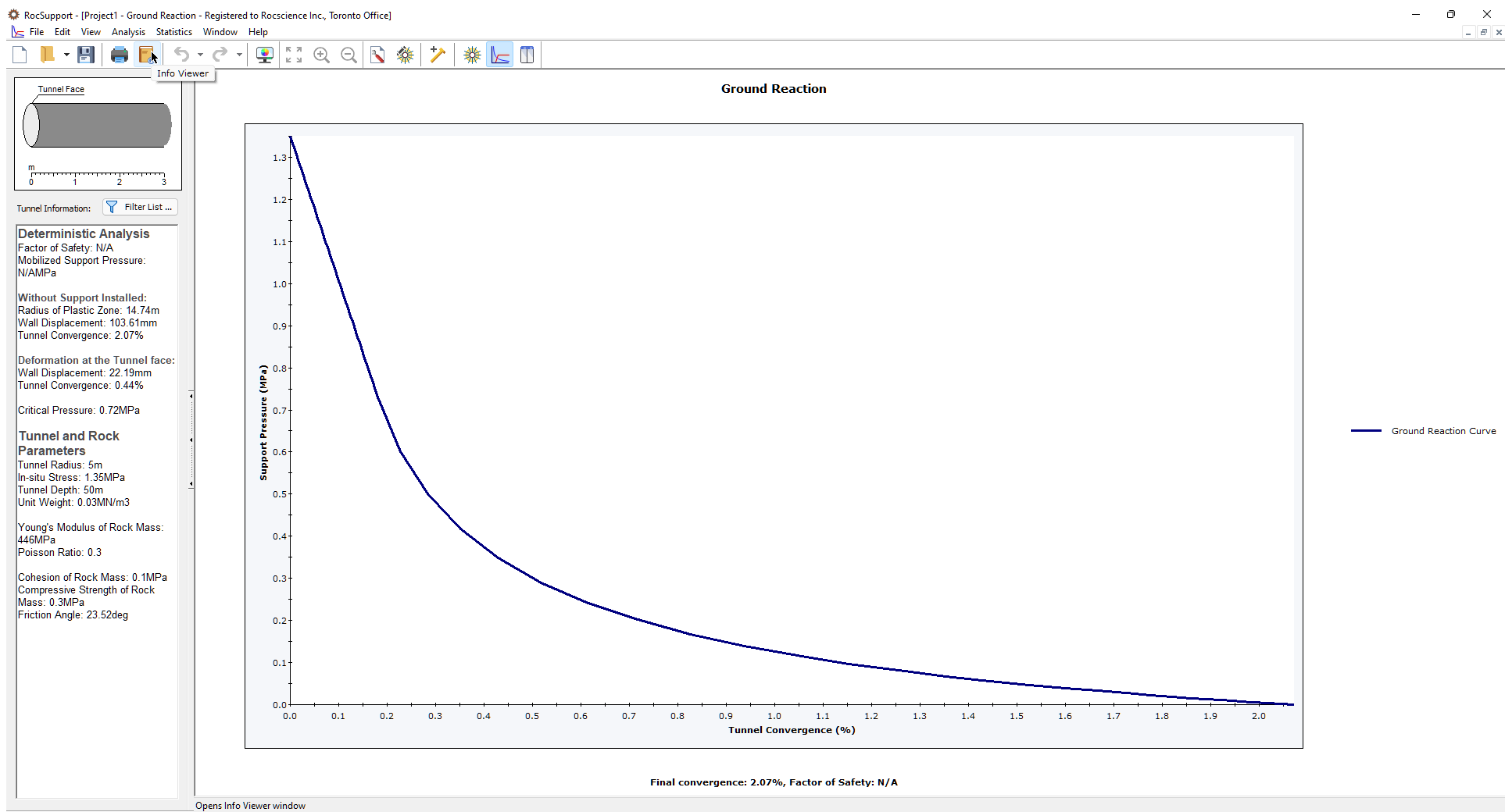
When a new file is created, the Ground Reaction View is displayed. The view shows the Ground Reaction Curve based on the default Tunnel and Rock Parameters.
2.2 TUNNEL SECTION VIEW
To view a cross-sectional view of the model, open the Tunnel Section View:
- Select Analysis > Tunnel Section
 in the menu or click the icon in the toolbar.
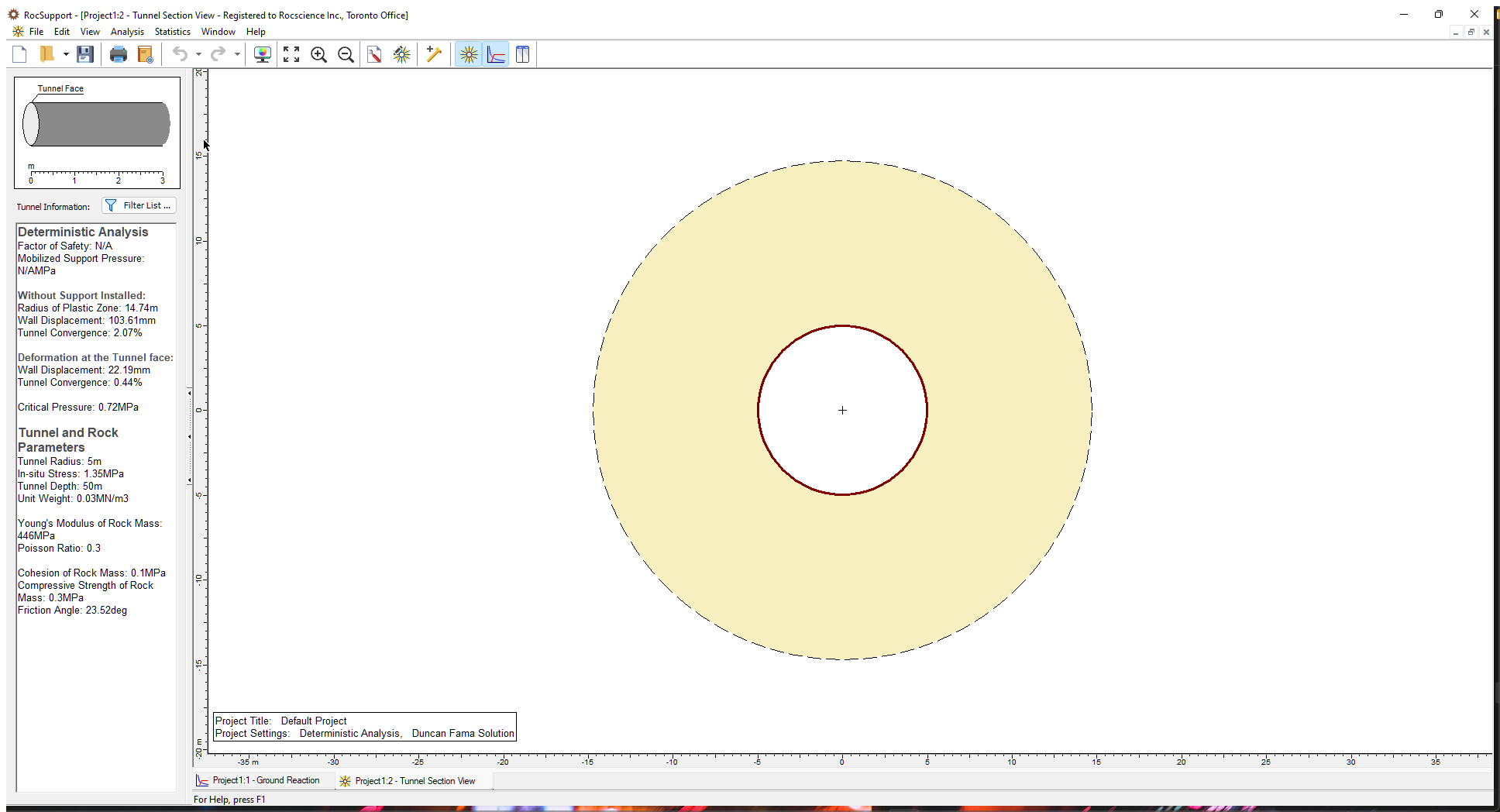
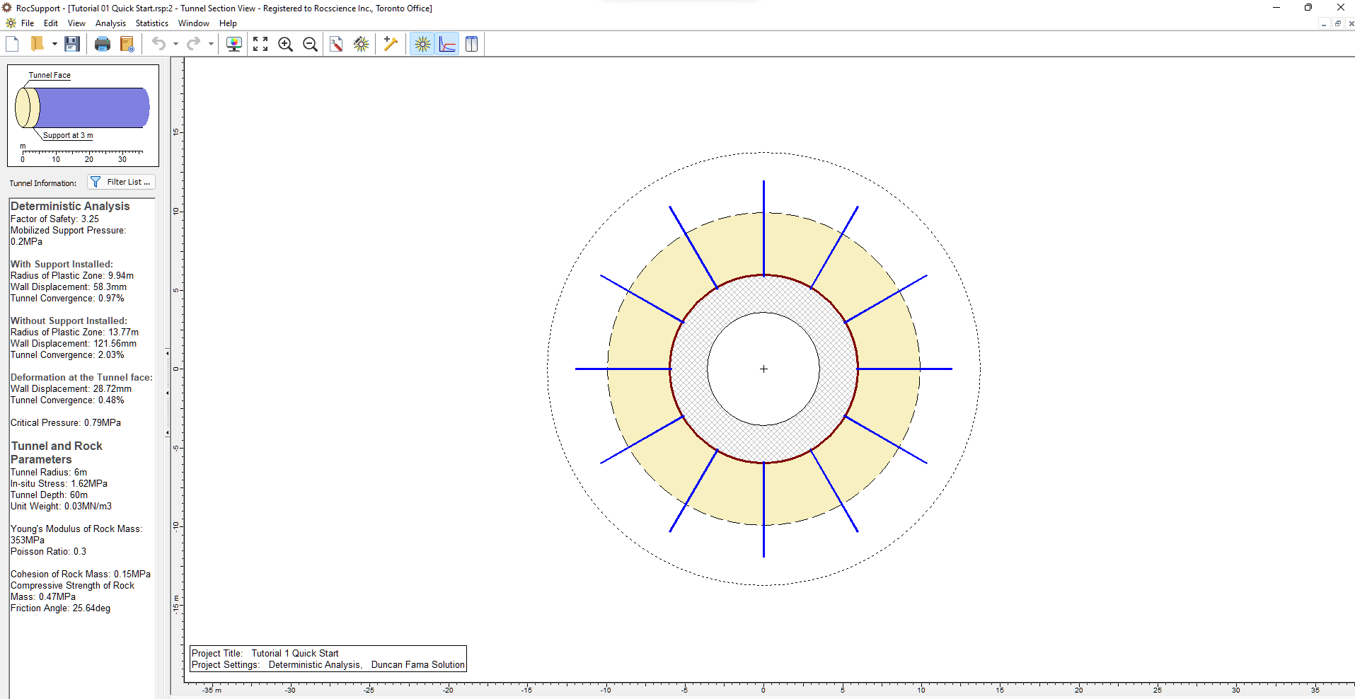
The Tunnel Section View displays:
- A cross-section of the tunnel diameter and the plastic zone (shaded region). The size of the plastic zone is drawn to scale with respect to the tunnel diameter.
- A Project Info Textbox with a summary of the main input and output parameters. Display of the textbox can toggled on and off using the right-click menu. The textbox position, colour, and font can be customized by double-clicking on the textbox.
- If support is installed, it is displayed on the Tunnel Section View and the plastic zone radius (with support) is displayed.
3.0 Project Settings
Although we do not need to change any Project Settings for this example, let’s take a look at the Project Settings dialog. To open the dialog:
- Select Analysis > Project Settings
 in the menu or click on the icon in the toolbar.
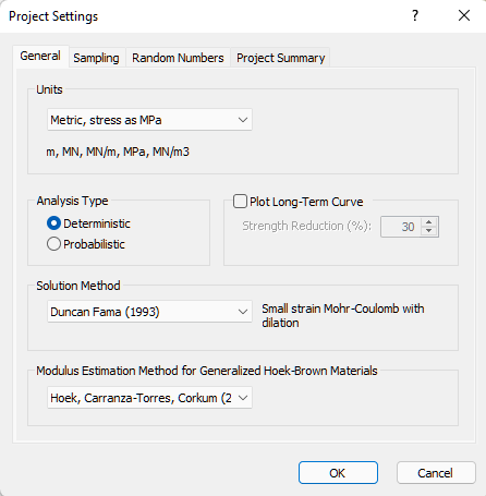
In the Project Settings dialog, you can set:
- General: Units, Analysis Type, Solution Method, Modulus Estimation Method for Generalized Hoek-Brown Materials, and Plot Long-Term Ground Reaction Curve option
- Sampling: Sampling Method and Number of Samples
- Random Numbers: Random Number Generation method
- Project Summary: Project Title, Analysis, Author, Company, Date Created, and Comments
For more help on Project Settings, see RocSupport Project Settings Overview.
4.0 Tunnel and Rock Parameters
The Tunnel Radius, In-Situ Stress, and Strength Properties of the Rock Mass are defined in the Tunnel and Rock Parameters dialog.
- Select Analysis > Tunnel Parameters
 in the menu or click on the icon in the toolbar.
For a Deterministic analysis, the Tunnel and Rock Parameters dialog appears as shown below:
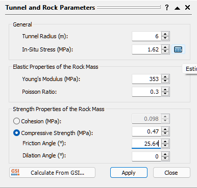
Because we are using the Duncan Fama solution method, based on the Mohr-Coulomb failure criterion, you can define either Cohesion or Compressive Strength under Strength Properties of the Rock Mass. If you select Compressive Strength, you must define a Friction Angle and Dilation Angle.
4.1 TUNNEL RADIUS
Note that you must input the Tunnel Radius and NOT the tunnel diameter in the Tunnel and Rock Parameters dialog! For this example, the tunnel diameter is 12 meters, so:
- Enter a Tunnel Radius of 6 meters.
4.2 IN-SITU STRESS
In the Tunnel and Rock Parameters dialog, you may input the hydrostatic In-Situ Stress directly, if it is known. However, as you will discover with other input data in RocSupport, whenever you see a Calculator icon  in an input data dialog, the required input data may be estimated from other parameters. In the case of In-Situ Stress, this can be simply estimated from the tunnel depth and the rock unit weight.
- In the Tunnel and Rock Parameters dialog, select the Calculator icon to the right of the In-Situ Stress edit box.
The Estimate In-Situ Stress dialog appears.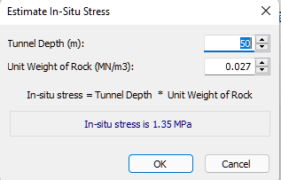
- Enter a Tunnel Depth of 60 meters.
- Keep the default value for Unit Weight of Rock (0.027 MN/m3).
- To use the estimated In-Situ Stress (1.62 MPa), click OK.
The estimated value is loaded into the Tunnel and Rock Parameters dialog.
The estimated In-Situ Stress is simply the product of the Tunnel Depth and Unit Weight of Rock:
po = γ * H
where: po = in-situ stress
γ = rock unit weight
H = tunnel depth below ground surface
4.3 ROCK PARAMETERS
Now let’s enter the elastic and strength parameters for the rock.
Remember from the beginning of this example that the rock properties were given in terms of Hoek-Brown parameters. However, the Duncan Fama solution method uses the Mohr-Coulomb failure criterion and requires a Friction Angle. For this purpose, the Calculate from GSI  option is provided in the Tunnel and Rock Parameters dialog.
In this example, we will enter the Compressive Strength, instead of the Cohesion.
- Select the Compressive Strength to activate it - you will notice that Cohesion is no longer active.
- Select the “Calculate from GSI” button, and you will see the following dialog.
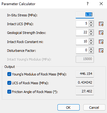
This dialog allows you to obtain estimates of the following rock mass properties
- Young’s Modulus
- Compressive Strength
- Friction Angle
by entering values of the Hoek-Brown parameters GSI, mi, intact UCS and D. The ability to calculate these parameters is very useful because the rock mass modulus, compressive strength and friction angle are usually not very well known quantities, whereas GSI, intact mi, intact UCS are often more readily available parameters.
The calculations are based on the equations and methods presented in Hoek, Carranza- Torres and Corkum (2002). This paper presents the latest developments in the Hoek-Brown failure criterion, including an improved method of determining equivalent Mohr-Coulomb parameters from the Hoek-Brown failure envelope.
Young’s Modulus is estimated using the Modulus Estimation Method specified in Project Settings.
- In the Parameter Calculator dialog, enter the following values: Intact UCS = 7, GSI = 15, Intact mi = 10. You should see the following output values for Young’s Modulus, rock mass UCS and rock mass Friction Angle.
TIP: You can use the check boxes in the dialog to select which output variables will be calculated. This is useful if you only wish to calculate some variables, and manually enter known values for other variables.
Before you select OK, notice that beside each edit box is a “pick”  button. Whenever you see this icon displayed in a RocSupport dialog, this means that data can be selected or estimated from a table or chart. Let’s examine this now.
- In the Parameter Calculator dialog, select the “pick” button beside the GSI edit box. You will see the following GSI table, allowing you to estimate a value for GSI based on the rock structure and surface conditions.

Note:
- as you move the mouse around the chart, the GSI value at that point will be displayed beside the cursor
- if you click the mouse at a point on the chart, the corresponding GSI value will be loaded into the edit box at the top of the GSI table
- you may then edit this value, if necessary
The significance and derivation of the Geological Strength Index will not be discussed in this tutorial. However, it should be emphasized that a parameter such as GSI should not be considered an exact value, and a range of possible values should always be considered in an analysis. For further information see Hoek et. al. (1995).
- Since we have already decided on a value for GSI, select Cancel in the GSI dialog.
- Now select the “pick” button beside the “Intact Rock Constant mi” edit box. You will see the following dialog, allowing you to select a value for mi based on rock type.
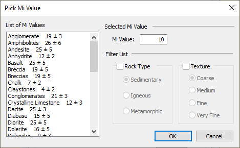
To use this dialog:
- simply select a rock type from the list at the left of the dialog, and the corresponding mi value will be loaded into the edit box at the top of the dialog.
- you may filter the list, if desired, by selecting the Rock Type and / or Texture check boxes, and then selecting the desired Rock Type and / or Texture. This will display only the requested subset in the list. This is left as an optional exercise for the user to experiment with.
- Since we have already decided on a value for mi, select Cancel in the Pick Mi Value dialog.
- Select OK in the Parameter Calculator dialog, to return to the Tunnel and Rock Parameters dialog.
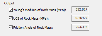
The computed values of modulus, compressive strength and friction angle are automatically entered in the Tunnel and Rock Parameters dialog. Notice that the number of decimal places have been rounded appropriately for each parameter (e.g. decimal places are not warranted for the rock mass Young’s modulus!)
We are now finished entering all of the desired data in the Tunnel and Rock Parameters dialog.
In order to save the newly entered parameters, and re-run the analysis, you must select the Apply button.
- Select Apply in the Tunnel and Rock Parameters dialog.
All analysis results in the Ground Reaction View and the Tunnel Section View will be updated with the new results.
- Close the dialog by selecting either the Close button, or the X in the upper right corner of the dialog.
5.0 Analysis Results (No Support)
5.1 TUNNEL SECTION VIEW
If you are not already viewing it, switch to the Tunnel Section View .
Select Zoom All to maximize the model within the view (you can also use the F2 function key to Zoom All):
- Select View > Tunnel Section > Zoom All

A summary is provided in Sidebar and the Project Info Textbox:
Note the Plastic Zone radius (no support) = 13.8 m and the final Tunnel Convergence = 2.0 %
With an unsupported Tunnel Convergence of 2.0 %, this tunnel falls into “category B” according to the guidelines discussed in the Appendix, for a first estimate of support requirements. This indicates that appropriate support would involve rockbolts and shotcrete. See the Appendix for more information.
5.2 GROUND REACTION CURVE
To view the Ground Reaction Curve:
- Select Analysis > Ground Reaction
 in the menu or click the icon in the toolbar.
By default, the X-axis of the Ground Reaction Curve is expressed as Tunnel Convergence (%). The X-axis can also be displayed as Wall Displacement, using a convenient right-click shortcut.
- Right-click on the view and select Horizontal Axis > Wall Displacement from the popup menu. The X-axis of the Ground Reaction plot is now in terms of Wall Displacement rather than Tunnel Convergence.
- Right-click again on the view and select Horizontal Axis > Tunnel Convergence to reset the X-axis to Tunnel Convergence.
6.0 Adding Support
Now let’s add some rockbolt support, and see the effect on the tunnel behaviour. To add support:
- Select Analysis > Support Parameters
 in the menu or click the icon in the toolbar.
Based on the unsupported analysis results, what type of support would be appropriate for this problem?
As described in the Appendix, this problem, with an unsupported Tunnel Convergence of 2.0%, falls into a category of tunneling problems, which can be stabilized with relatively modest support (e.g. rockbolts and shotcrete).
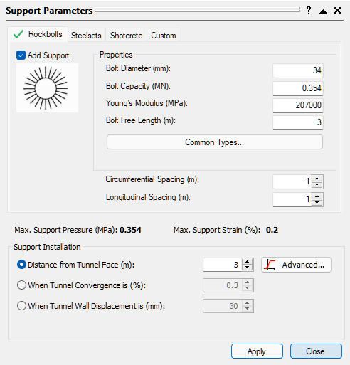
We will start by adding 34 mm rockbolt support, at 1 x 1 m pattern spacing. Support will be installed at a distance of 3 m from the face.
To add the rockbolt support:
- Select the Add Support check box under the Rockbolts tab. Notice that a green check mark now appears beside the Rockbolts tab, to indicate that rockbolt support will be in effect.
- We will use 34 mm rockbolts, which is already selected by default in the Type list.
- We will use the default Pattern Spacing = 1 x 1 m.
- Enter Distance from Tunnel Face = 3m. The dialog should appear as follows:
- Select the Apply button. This will save the support parameters you have entered, and rerun the analysis. All open views of the current document, will be updated with the latest analysis results.
6.1 MAXIMUM SUPPORT PRESSURE AND STRAIN
Before we close the Support Parameters dialog, we will comment on the Maximum Support Pressure and Maximum Support Strain, which are displayed in the dialog.
![]()
Note:
- These values CANNOT be edited; they are pre-defined, calculated values (Hoek, 1999) based on the support parameters you have selected.
- For a given tunnel diameter, the Maximum Support Pressure depends on the type of support you have added, as well as the Out of Plane Spacing (for steel sets) or the Pattern Spacing (for rockbolts)
- The Maximum Support Strain depends only on the support type you have selected, and is not affected by Out of Plane Spacing or Pattern Spacing.
- If none of the pre-defined support types (Rockbolts, Steel Sets or Shotcrete) provide the required Support Pressure and Support Strain, then the user can simply define a Custom support type in the Support Parameters dialog. See the RocSupport Help system for details about defining Custom support.
- Different support types (e.g. Rockbolts and Shotcrete) can be combined in the same analysis. This is discussed later in this tutorial.
In this example, for the support parameters we have entered, Maximum Support Pressure = .354 MPa and Maximum Support Strain = 0.2 %.
Now close the Support Parameters dialog (make sure you have selected Apply before you select Close), and we will discuss the results of the analysis with support.
7.0 Analysis Results (with Support)
If the Tunnel Section View is not currently active, then select the Tunnel Section option from the toolbar or the Analysis menu, to view the Tunnel Section and analysis summary.
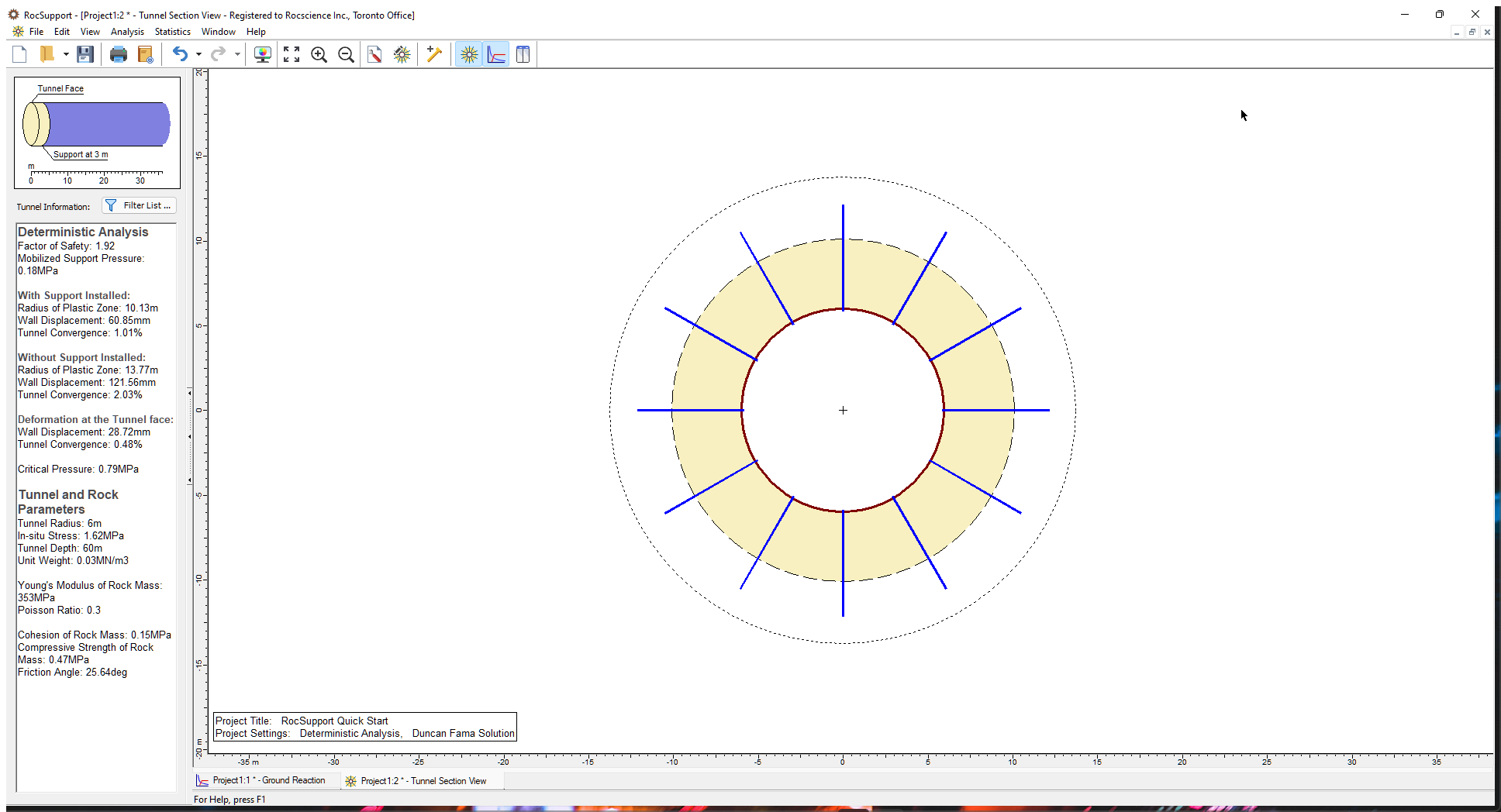
Notice that there are now two plastic zone radius boundaries displayed (dotted lines). The interior boundary shows the extents of the plastic zone (shaded region) around the tunnel when support is installed. The outer boundary depicts the plastic zone when the problem is analyzed without support.
When you place the mouse pointer in the shaded region, a tool tip appears that reads “Plastic zone: 10.13 m.” When you move the pointer to the outer boundary the tip changes to “Unsupported plastic zone: 13.77 m.”
The analysis summary in the Project Info textbox provides values of:
- Factor of Safety
- Mobilized Support Pressure
- Plastic Zone Radius (decreased from 13.8 meters to 10.1 meters with support)
- Tunnel Convergence (decreased from 2.0 % to 1.0 % with support)
7.1 FACTOR OF SAFETY
The factor of safety for the rockbolts is 1.92. See the Introduction Manual for a definition of the Factor of Safety in RocSupport.
Although this would be considered an adequate Factor of Safety in other types of analyses (e.g. limit equilibrium slope stability), in a rock support interaction analysis this may not be the case, due to the assumptions inherent in the analysis. See the Introduction Manual for more information.
7.2 MOBILIZED SUPPORT PRESSURE
The Mobilized Support Pressure listed in the Project Info Textbox is the Support Pressure determined from the intersection of the Ground Reaction and Support Reaction Curves, as discussed in the next section.
When the Factor of Safety is greater than 1, this value will always be LESS than the Maximum (Available) Support Pressure.
7.3 PLASTIC ZONE RADIUS
The rockbolt support has reduced the radius of the plastic zone from 13.8 meters to 10.1 meters.
By default, RocSupport extends bolts 2.0 m beyond the plastic zone, when drawing the bolts on the screen. For the current example, this makes the rockbolt support approximately 6 meters in length. The default value of 2.0 m can be changed in the Section View tab of the Display Options  dialog.
8.0 Ground Reaction and Support Reaction
Now select the Ground Reaction view, which will display the Ground Reaction and Support Reaction curves on the same plot.
- Select Analysis > Ground Reaction
As discussed in the Introduction Manual, note the following about the Support Reaction Curve:
- The origin of the Support Reaction Curve, on the horizontal (Tunnel Convergence) axis, is determined using the Distance from Tunnel Face in conjunction with the Longitudinal Deformation Profile. See the Introduction Manual for details about how this value is determined.
- The slope of the elastic portion of the Support Reaction curve, is equal to the Maximum Support Pressure divided by the Maximum Support Strain.
- The intersection of the Support Reaction with the Ground Reaction, determines the mobilized support pressure, final tunnel convergence (with support) and plastic zone radius, listed in the Tunnel Section View.
If the Ground Reaction Curve intersects the Support Reaction Curve in the elastic region, as in this example, then the mobilized Support Pressure and Tunnel Convergence are considered EQUILIBRIUM values.
9.0 Combining Support Types
As mentioned earlier in this tutorial, the Support Parameters dialog allows multiple support types to be added for a given model.
For example, Rockbolts and Shotcrete could be added to the same model, simply by selecting the Add Support check box for both Rockbolts and Shotcrete, and entering the desired parameters for each.
When multiple support types are used for a single model, the following rules apply to the Maximum Support Pressure and Maximum Support Strain:
- The Maximum Support Pressure is cumulative, and is ADDED for all applied support types.
- The Maximum Support Strain is the MAXIMUM value of all applied support types.
These simplistic assumptions are of course not intended to model the actual, complex interaction of multiple support systems, but are an idealized approximation.
For our current example, also remember that:
- The guidelines described in the Appendix suggest that rockbolts and shotcrete together, would be appropriate support for this tunnel.
So, let’s add some shotcrete support to the rockbolt support, and see the effect on the analysis results.
- Select Analysis > Support Parameters to open the Support Parameters dialog.
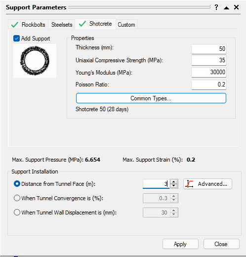
- Select the Shotcrete tab.
- Select the Add Support check box.
- Notice that green check marks now appear on BOTH the Rockbolts tab and the Shotcrete tab, indicating that both rockbolt and shotcrete support will be in effect.
- Select the 50 mm thickness, 28-day age shotcrete type from the Properties list.
- Select the Apply button, to save the shotcrete parameters and re-run the analysis. All open views of the current document, will be updated with the latest analysis results.
Before we close the Support Parameters dialog, notice the Maximum Support Pressure and Maximum Support Strain values listed in the dialog. These are now the COMBINED values, for the rockbolts AND shotcrete.
As discussed above:
- the (combined) Maximum Support Pressure is the SUM of the 34 mm rockbolt support pressure and the 50 mm shotcrete support pressure (.354 + .290 = .644)
- the (combined) Maximum Support Strain is simply the maximum of the rockbolt (0.2) and shotcrete (0.1) values, and is therefore equal to 0.2.
- Now close the dialog and observe the new analysis results
Note that the thickness of shotcrete (or steel set) support is now drawn to scale in the Tunnel Section View . If desired, it can be drawn either with a specified thickness in mm or as a percentage of tunnel radius, as selected in the Display Options dialog (use the Thickness of Support Layer option in the Section View tab of the Display Options dialog). This is left as an optional exercise for the user to experiment with.
10.0 Analysis Results (with Combined Support)
As we did after adding rockbolt support, examine the information in the Tunnel Section View and the Ground Reaction / Support Reaction View. The following table summarizes the results with No Support, Rockbolt Support, and Combined Rockbolt / Shotcrete Support.
No Support | Rockbolts | Rockbolts + Shotcrete | |
Factor of Safety | N/A | 1.9 | 3.3 |
Mobilized Support Pressure (MPa) | N/A | 0.18 | 0.20 |
Plastic Zone Radius (m) | 13.8 | 10.1 | 9.9 |
Tunnel Convergence (%) | 2.0 | 1.0 | 0.97 |
It can be seen that the addition of shotcrete support did not have a great effect on the plastic zone radius, tunnel convergence or mobilized support pressure, compared to the rockbolt support alone.
This is because the additional support capacity, in this case, has not significantly changed the intersection point of the Ground Reaction and Support Reaction curves, which determines these values. Compare the two curves before and after the shotcrete was added.
However, the Factor of Safety for the combined support has been significantly increased, from 1.9 to 3.3. This might now be considered an adequate safety factor for the support system.
Keep in mind that we used the 28-day shotcrete strength. The support pressure provided by the shotcrete at early ages is much less than the 28-day strength, and this must be taken into consideration when considering the actual combined safety factor, at different stages of the shotcrete curing.
(Note that 3-day and 0.5-day 50 mm shotcrete support, is also available in the Support Parameters dialog). You can also add a custom shotcrete support using the Custom check box.
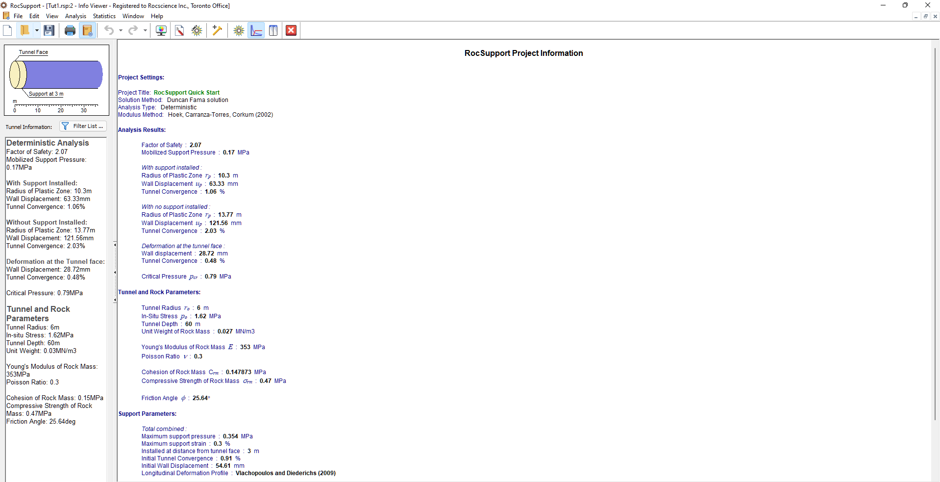
11.0 Info Viewer
Finally, let’s look at the Info Viewer option. The Info Viewer option provides a well-formatted summary of all input and output data.
- Select Anlaysis > Info Viewer

If necessary, scroll down to view all of the information in the Info Viewer. The font size can be changed in the View menu.
Notice that the Support Parameters information lists the Total Combined (Maximum Support Pressure and Maximum Support Strain), as well as the contributions from each individual support type used in the model (in this case, rockbolts and shotcrete).
The Info Viewer text can be copied to the Windows clipboard, by selecting the Copy to Clipboard option from the Edit menu, or by right-clicking in the Info Viewer and selecting Copy to Clipboard. From the Windows clipboard, the text can be pasted into other applications for report writing, presentations, etc.
The Info Viewer text can also be saved to a file, by right-clicking in the view and selecting Save As .rtf file or Save As .txt file. A Rich Text Format file (.rtf file) preserves the formatting of the text, as it is displayed in the Info Viewer. A plain text file (.txt file) saves the text only, with no formatting.
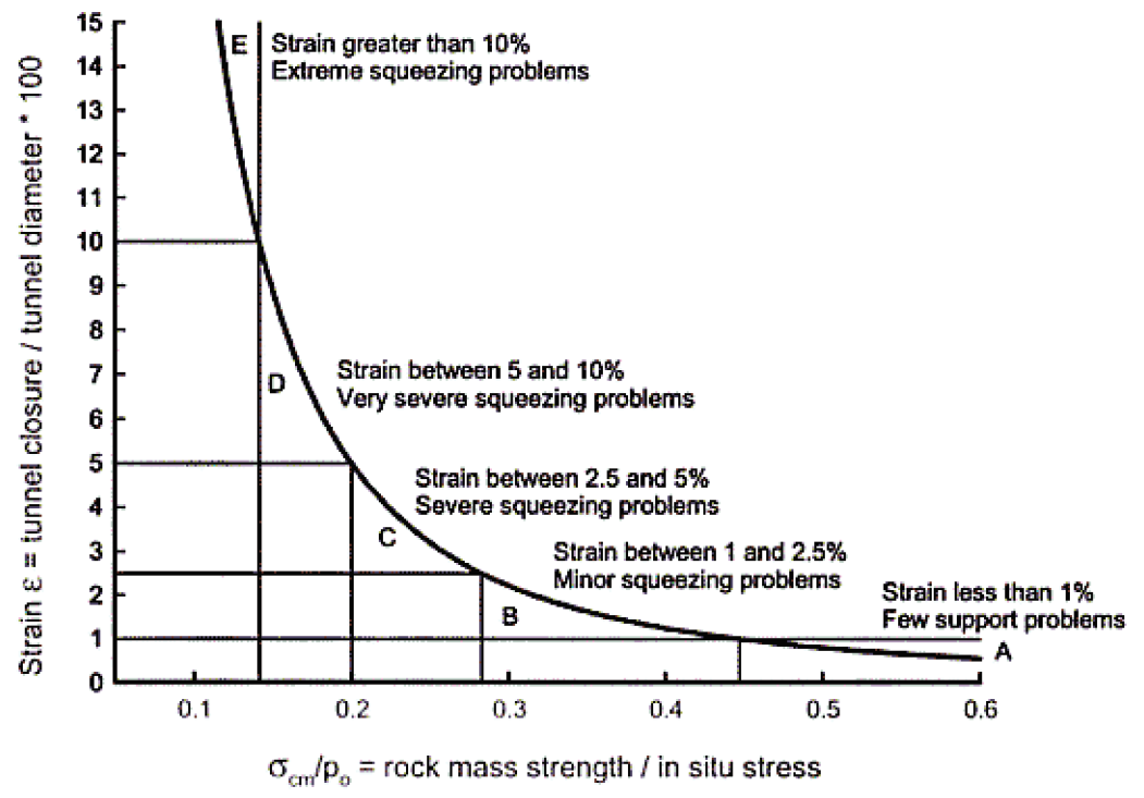
12.0 First Estimate of Support Requirements
It has been demonstrated that the stability of tunnels in weak rock, is controlled by the ratio of the uniaxial compressive strength of the rock mass to the maximum in-situ stress. This ratio provides a guide to the first estimate of support requirements (Hoek, 1998).
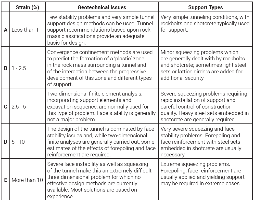
The results of the latest studies (Hoek and Marinos, 2000) are summarized in the following graph and corresponding table. Although the categories A to E are somewhat arbitrary, they are based on considerable experience, and are considered adequate as a first indication of tunneling difficulty.
Note that this relationship is for an unsupported tunnel. Strain is defined as 100 x the ratio of tunnel closure to tunnel diameter.
This concludes the Quick Start Tutorial.