1 - Underground Tunneling
1.0 Introduction
This tutorial is a simple introductory to help you become familiar with the Underground Tunnel option as well as basic modeling and data interpretation features of EX3.
Topics Covered in this Tutorial:
- Importing Geometry
- Underground Tunnels
Finished Product:
The finished product of this tutorial can be found in the Tutorial_01_-_Underground_Tunnel.Examine3 data file. All tutorial files installed with EX3 can be accessed by selecting File > Recent Folders > Tutorials Folder from the EX3 main menu.
2.0 Model
2.1 Project Settings
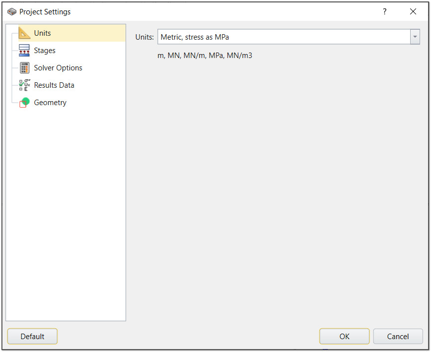
When you open EX3 a new project file will automatically be created. For this tutorial, you will need to ensure your units are set to Metric. To do so:
- Select Analysis > Project Settings (CTRL + J) from the menu or click on the Project Settings
 icon in the toolbar.
 - Select the Units tab and ensure the units are set to Metric, stress as MPa.
2.2 Import Geometry
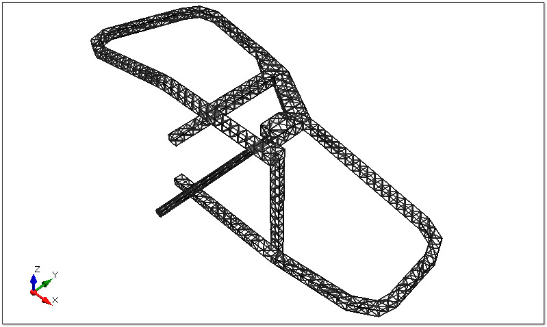
In order to model the underground tunnel, you will need to first import the geometry. A sample file has been provided in the Tutorials folder.
- Select File > Import > Import Geometry from the menu.
- Select the underground-obj.rsgeomobj file, which can be found in the Tutorials > Tutorial 01 - Underground Tunnel folder. A new dialog will open.
- Check the All Geometry check box to select all the options below.
- Click Post-Processing.
- Click Done to close the dialog.
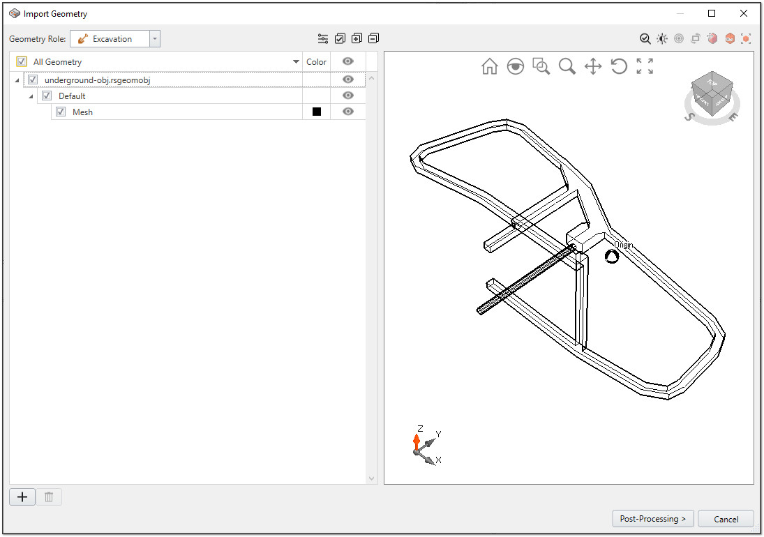
You should now see the model in the four view panels.
2.3 Material Assignment
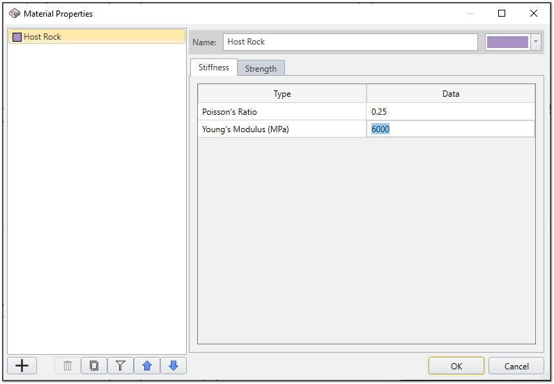
- Select Materials > Define Materials in the menu or click on the Define Materials
 icon in the toolbar.
 - For the Host Rock, enter the following values:
- In the Strength tab:
- Strength Criterion = Morh Coulomb
- In the Stiffness tab:
- Poisson's Ratio = 0.25
- Young's Modulus (MPa) = 6000
- In the Strength tab:
- Click OK to close the dialog.
3.0 Loading
3.1 Adding Stress Loading
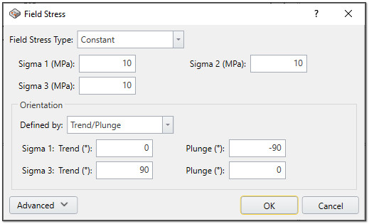
- Select Loading > Field Stress from the menu or go to the Loads tab and click the Field Stress
 icon in the toolbar.
 - Leave the defaults as is and click OK.
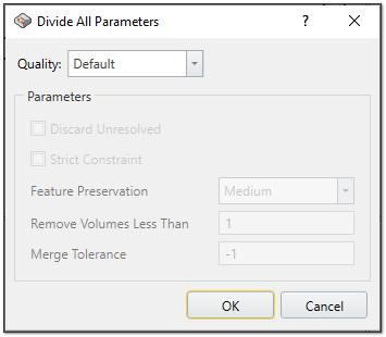
- Divide all by selecting Geometry > Divide All Geometry in the menu.
- Leave the defaults as is and click OK.
The program will automatically create the mesh in the background. You can view the mesh by clicking on the Mesh workflow tab.
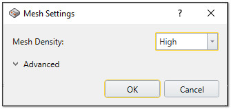
5.0 Modifying the Mesh
To adjust the density of your mesh:
- Select Mesh > Mesh Settings (CTRL + M) from the menu or go to the Mesh workflow tab and click the Mesh Settings
 icon in the toolbar.
 - Set the Mesh Density to High.
- Click OK to close the dialog.
6.0 Field Points
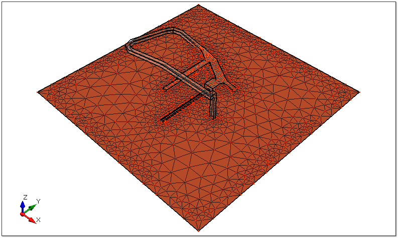
To see the results around an excavation, field points need be defined. Users can define as many field points as they need. To do so:
- Select Field Points > Add Field Points Plane > XY Field Points Plane from the menu or go to the Field Points workflow tab and click on Field Points Plane
 icon in the toolbar.
 - You can adjust the mesh density to define the amount of field points. For this tutorial, we will set the Mesh Density to High.
- Use your mouse to move the plane and insert it in the area of interest.
- Click OK to close the dialog.
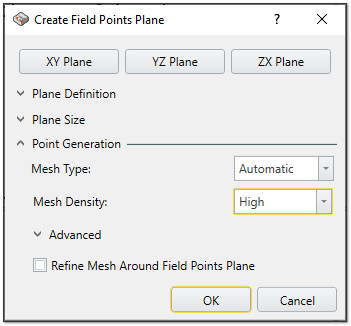
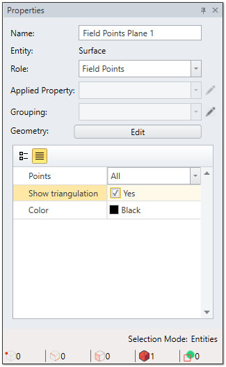
To see the visualization triangulation, select the Field Points Plane in the view port and check the Show Triangulation box in the Properties panel.
7.0 Compute
Save and compute your results by selecting Compute > Compute from the menu or selecting the Compute workflow tab and clicking on the Compute  icon in the tool bar.
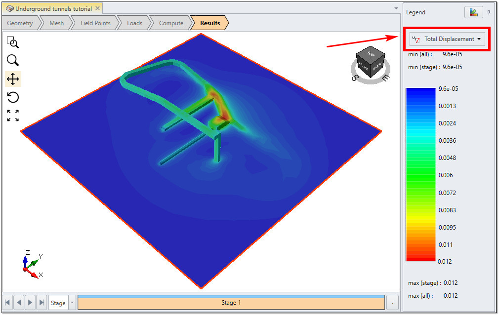
8.0 Results Visualization
After computing, you have several options for viewing your results. You can view Displacement (X, Y, Z, Total Displacement) and Stress (Sigma1, Sigma 2, Sigma 3, mean stress, Sx, Sy, Sz, Sxy, Syz, Sxz). Use the drop down in the contour legend (on the right side of the screen) to make your selection.
This concludes the Underground Tunnel tutorial; you may now exit the EX3 program.