2 - Materials and Staging
1.0 Introduction
This tutorial is a simple introductory to help you become familiar with the Multi Material option as well as basic modelling and data interpretation features of EX3.
Topics Covered in this Tutorial:
- Multi Staging
- Multi Material
Finished Product:
The finished product of this tutorial can be found in the Tutorial_02_-_Materials_and_Staging.Examine3 data file. All tutorial files installed with EX3 can be accessed by selecting File > Recent Folders > Tutorials Folder from the EX3 main menu.
2.0 Model Setup
2.1 Project Settings
When you open EX3 a new project file will automatically be created. Begin the tutorial by opening the Project Settings. To do so:
- Select Analysis > Project Settings (CTRL + J) from the menu or click on the Project Settings
 icon in the toolbar.
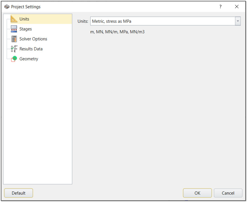
 - Select the Units tab and ensure the units are set to Metric, stress as MPa.
- Select the Stages tab change the Number of Stages to 4.
- Name the stages as follows:
- Click OK to close the dialog.
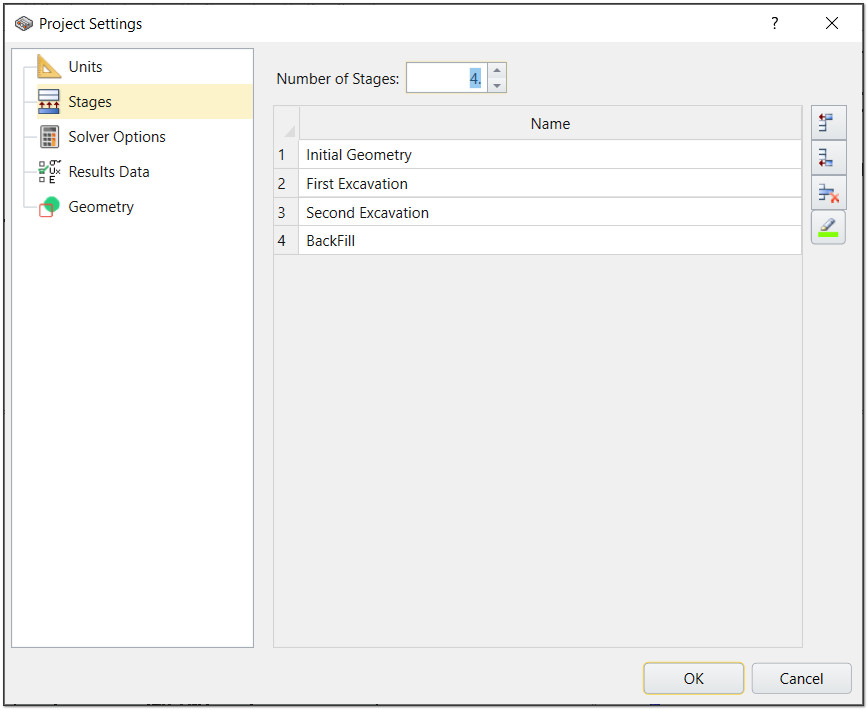
# | Name |
1 | Initial Geometry |
2 | First Excavation |
3 | Second Excavation |
4 | Backfill |
2.2 Material Properties
- Select Materials > Define Materials in the menu or click on the Define Materials
 icon in the toolbar.
 - By default, the first material is listed as Host Rock. Click on the Add
 button to add two more materials.
 - Select the Strength tab and enter Strength Criterion = Mohr Coulomb.
- Enter the following properties for each material:
- Click OK to close the dialog.
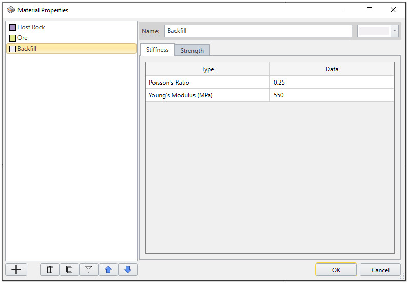
Material Name | Poisson's Ratio | Young's Modulus (MPa) |
Host Rock | 0.3 | 2000 |
Ore | 0.3 | 1000 |
Back Fill | 0.25 | 550 |
3.0 Geometry
3.1 Create a Plane
For this tutorial we will model a plane. To create a plane:
- Select Geometry > 3D Primitive Geometry > Plane from the menu or click on the Add 3D Primitives
 icon in the toolbar.
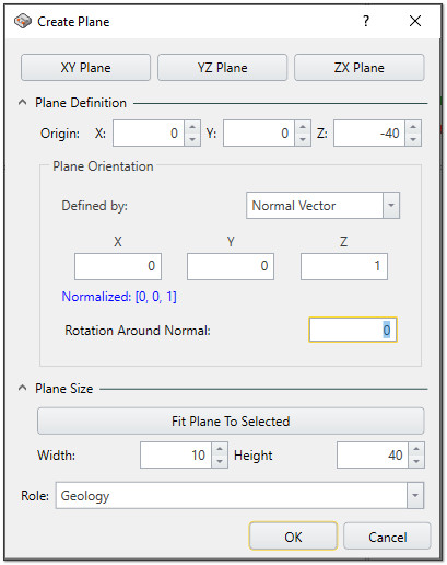
 - Expand the Plane Definition and Plan Size menus and enter the following values:
- X = 0
- Y = 0
- Z = -40
- Width = 10
- Height = 40
- Click OK to close the dialog.
Origin
Plane Size
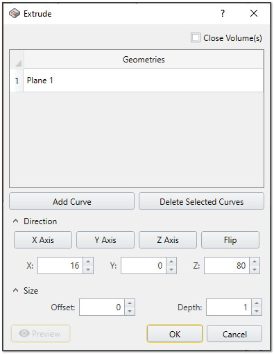
3.2 Extrude the Plane
- Select the plane by clicking on it in the viewport or selecting it in the Visibility Tree.
- Select Geometry > Extrude/Sweep/Loft Tools > Extrude in the menu or click on the Extrude
 icon in the toolbar.
 - Enter the Direction as X = 16, Y = 0, Z = 80.
- Click OK to close the dialog.
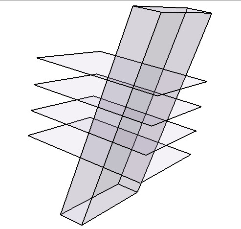
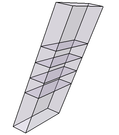
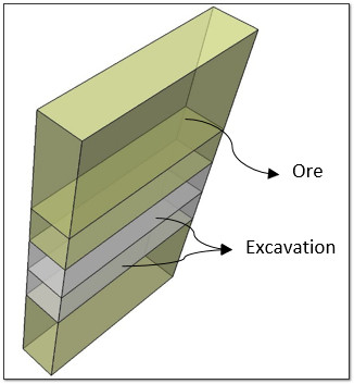
To define excavating zones, we will need to define four new planes in the following elevations:
Plane 1 | Z = -15.0 m |
Plane 2 | Z = -5.0 m |
Plane 3 | Z = 5.0 m |
Plane 4 | Z = 15.0 m |
The Plane Size for all four planes should be set to:
- Width = 50
- Height = 40
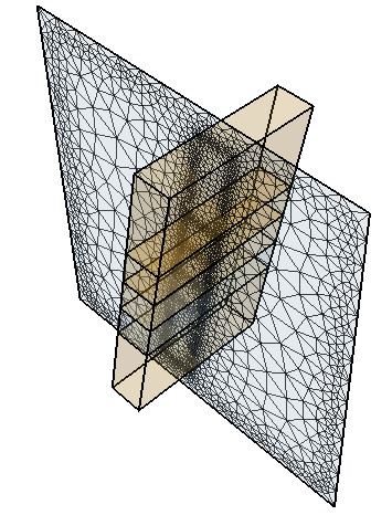
Your model should now look as follows:
4.0 Loading
The options in the Loading menu allow you to define all of the various types of loads which can be applied to an EX3 model. For this model, we will be defining the Field Stress.
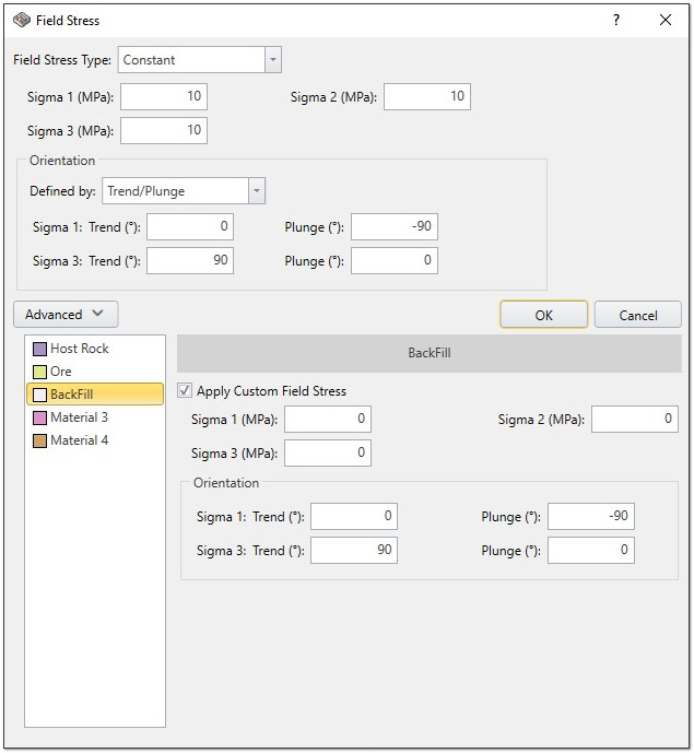
4.1 Adding Stress Loading
- Select Loading > Field Stress from the menu or go to the Loads tab and click on the Field Stress
 icon in the toolbar.
 - Leave the defaults as is and click on the Advanced button.
- For Backfill, select Apply Custom Field Stress and remove the initial stress by setting Sigma 1 (MPa), Sigma 2 (MPa), and Sigma 3 (MPa) to 0.
- Click OK.
- Divide all by selecting Geometry > Divide All Geometry in the menu.
- Leave the defaults as is and click OK.
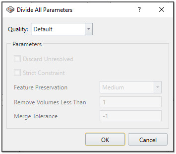
The program will automatically create the mesh in the background.
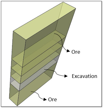
5.0 Material Assignment
You will now begin assign materials to the various stages. Begin by selecting your stage at the bottom of the window.
You can use the Visibility controls in the top left of the screen to select a section of the model or you can click on the model itself.
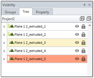
Use the Properties controls to select the Applied Property for each section.
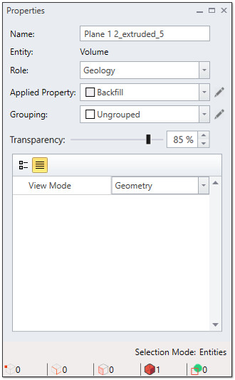
Define your stages as follows:
- Stage 1: Initial Geometry
- Stage 2: First Excavation
- Stage 3: Second Excavation

- Stage 4: Backfill

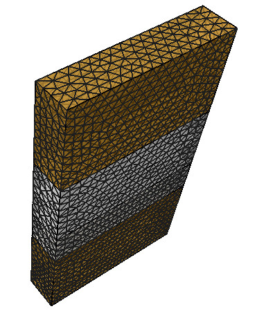
6.0 Modifying the Mesh
As mentioned previously, EX3 automatically creates the mesh in the background. You can view the mesh by clicking on the Mesh workflow tab.

To adjust the density of your mesh:
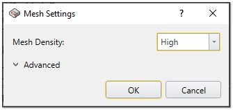
- Select Mesh > Mesh Settings (CTRL + M) from the menu or go to the Mesh workflow tab and click on the Mesh Settings
 icon in the toolbar.
 - Set the Mesh Density to High.
7.0 Field Points
To see the results around an excavation, field points need to be defined. User can define as many field points as they need.
7.1 Add a Field Points Plane
To add a Field Point Plane:
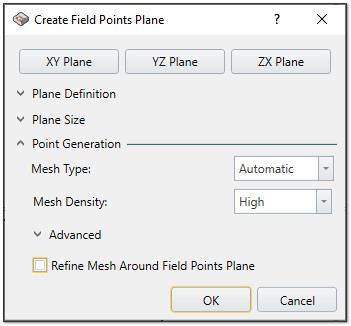
- Select Field Points > Add Field Points Plane > ZX Field Points Plane from the menu or go to the Field Points workflow tab and click on the Field Points Plane
 icon in the toolbar.
 - You can adjust the mesh density to define the amount of field points. For this tutorial, we will set the Mesh Density to High.
- Use your mouse to move the plane and insert it in the area of interest.
- Click OK to close the dialog.
8.0 Compute
Save and compute your results by selecting Compute > Compute from the menu or selecting the Compute workflow tab and clicking on the Compute  icon in the toolbar.
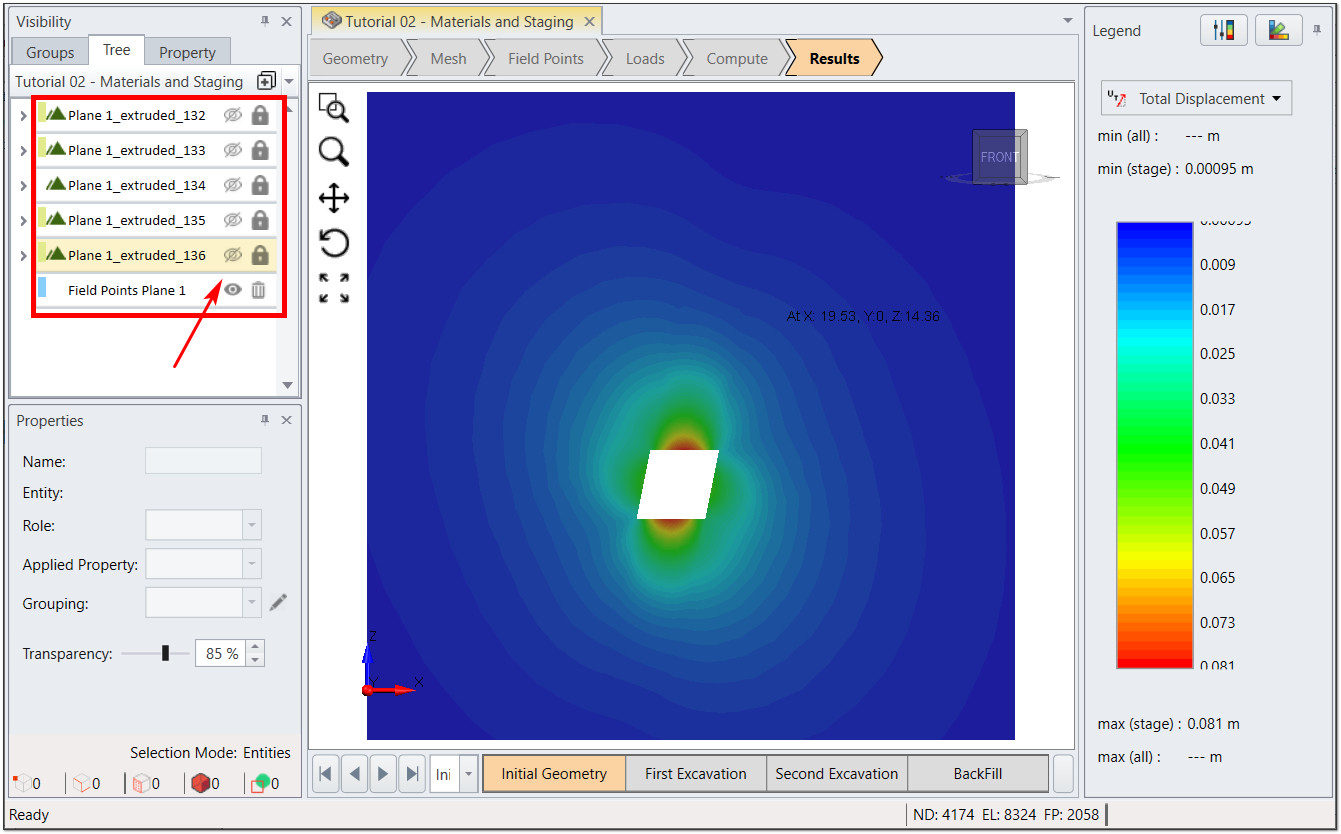
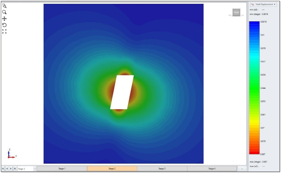
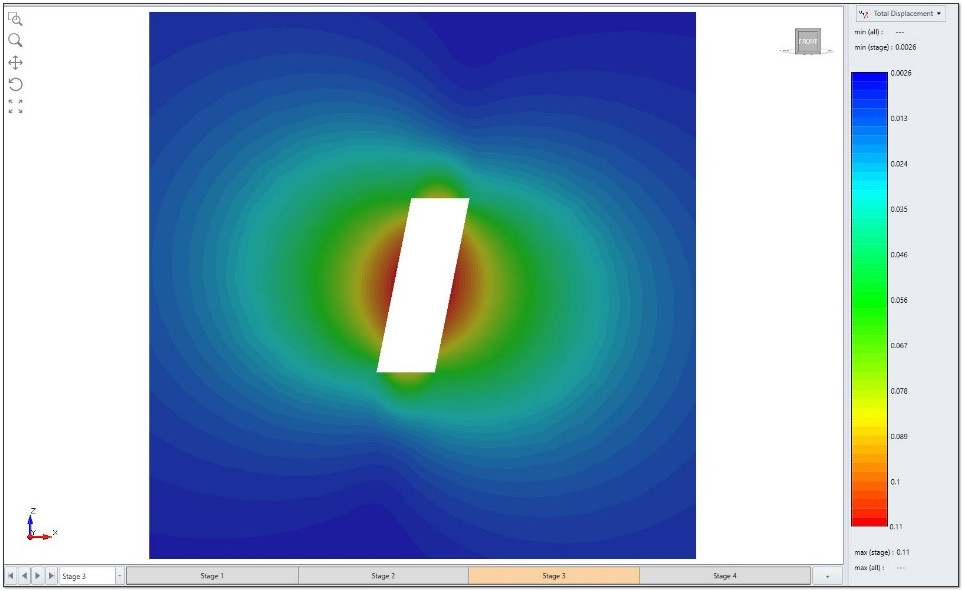
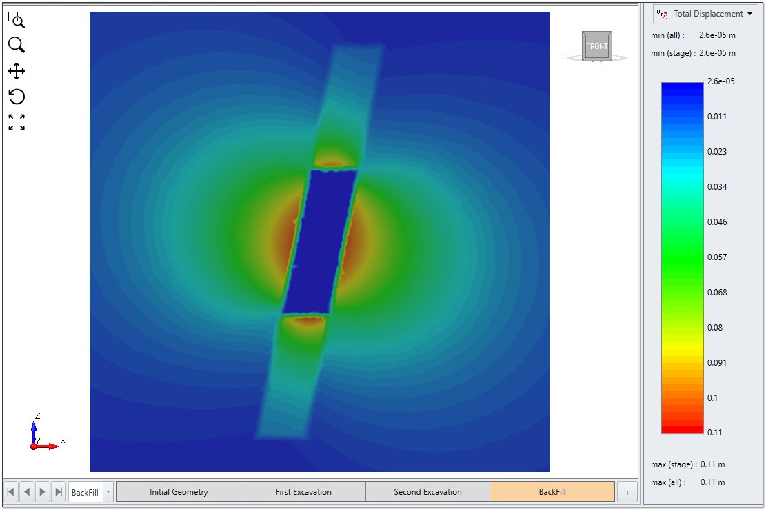
9.0 Results Visualization
After computing, you have several options for viewing your results. You can view Displacement (X, Y, Z, Total Displacement) and Stress (Sigma1, Sigma 2, Sigma 3, mean stress, Sx, Sy, Sz, Sxy, Syz, Sxz). Use the drop down in the contour legend (on the right side of the screen) to make your selection.
To see the results on the Field Point Plane, you can use the Visibility controls (on the left of the screen) to hide the backfill and ore zones.
This concludes the Multi-staging Multi Material tutorial; you may now exit the EX3 program.