8 - Kinematic Analysis (Toppling)
1.0 Introduction
Based on kinematic considerations and frictional properties of joint planes, it is possible to perform stability analyses such as toppling, Planar Sliding and Wedge Sliding on a stereonet. This tutorial demonstrates how to perform stability analyses under Flexural Toppling failure mode using the Kinematic Analysis option in Dips.
The tutorial is a continuation from Tutorial 07 - Feature Analysis (which uses the example file Examppit.dips8) . The data has been collected by a geologist working on a single rock face above the first bench in a young open pit mine.
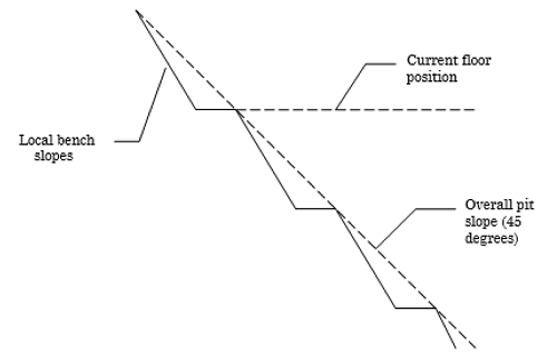
The rock face above the current floor of the existing pit has a dip of 45 degrees and a dip direction of 135 degrees. The current plan is to extend the pit down at an overall angle of 45 degrees. This will require a steepening of the local bench slopes, as indicated in the figure above. The local benches are to be separated by an up-dip distance of 16 m. The bench roadways are 4 m wide.
Topics Covered in this Tutorial:
- Kinematic Analysis of Toppling Failure Mode
- Friction Cones
- Shear Discontinuities
Finished Product:
The finished product of this tutorial can be found in the Tutorial 08 Kinematic Analysis (Flexural Toppling).dips8 and Tutorial 08 Kinematic Analysis (Direct Toppling).dips8 files, located in the Examples > Tutorials folder in your Dips installation folder.
2.0 Model
If you have not already done so, run Dips by double-clicking on the Dips icon in your installation folder. Or from the Start menu, select Programs > Rocscience > Dips > Dips.
If the Dips application window is not already maximized, maximize it now, so that the full screen is available for viewing the model.
To save us some time, this tutorial will use the Tutorial 07 Feature Analysis.dips8 file which already has the required pit slope plane (User Plane) and .
- Select File > Recent Folders > Tutorials Folder
 from the menu .
 - Open the Tutorial 07 Feature Analysis.dips8 file. Save this example file with a new file name without overwriting the original file.
- Select File > Save As
 from the menu.
 - Enter the file name Tutorial 08 Kinematic Analysis (Toppling) and Save the file.
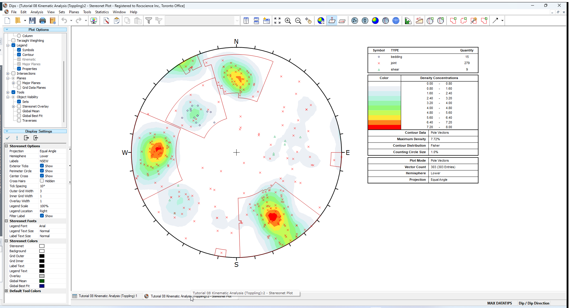
You should see the Stereonet Plot View shown in the following figure.
If you do not see the plot below, then use the Sidebar Plot Options to view pole vectors and contours on the stereonet.
3.0 Flexural Toppling
Let’s examine the Flexural Toppling failure mode.
- Select the Analysis > Kinematic Analysis
 from the menu.
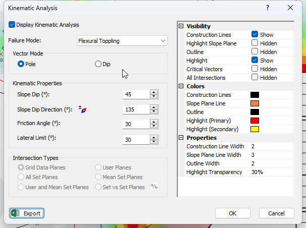
 - In the Kinematic Analysis dialog:
- Select Display Kinematic Analysis checkbox.
- Set the Failure Mode = Flexural Toppling in the dropdown.
- Enter Slope Dip = 45 degrees.
- Enter Slope Dip Direction = 135 degrees.
- Enter Friction Angle = 30 degrees.
- Enter Lateral Limits = 30 degrees.
- Select OK.
NOTE: You can alternatively toggle on/off the Display of Kinematic Analysis by selecting the Kinematic Analysis option in the toolbar. The Failure Mode, various Kinematic Properties (i.e., Slope Dip, Slope Dip Direction, Friction Angle, Lateral Limit), and Visibility settings can also be set in the Kinematic Analysis Sidebar.
You should see the Kinematic Analysis overlay for Flexural Toppling as shown below.
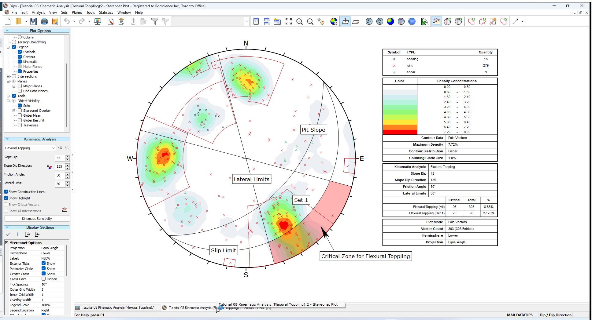
The key elements of Flexural Toppling Kinematic Analysis using pole vectors are:
- Slope Plane
- Slip Limit Plane (based on Slope Dip and Friction Angle)
- Lateral Limits
These are discussed below. Any poles that plot within the critical zone for Flexural Toppling represent a toppling risk. This analysis is based on the Flexural Toppling analysis described by Goodman [1].
3.1 SLOPE PLANE
The great circle of the Slope Plane is displayed, and labeled Pit Slope with orientation Dip / Dip Direction = 45 / 135.
3.2 SLIP LIMIT
Planes cannot topple if they cannot slide with respect to one another. Goodman [1] states that for slip to occur, the bedding normal must be inclined less steeply than a line inclined at an angle equivalent to the Friction Angle above the slope.
This results in a Slip Limit Plane which defines the critical zone for Flexural Toppling. The Dip angle of the Slip Limit Plane is derived from the folowing:
Slip Limit Dip = Pit Slope Dip – Friction Angle = 45 – 30 = 15 degrees
The Slip Limit Dip Direction is equal to that of the Slope face ( 135 degrees).
3.3 LATERAL LIMITS
The Lateral Limits for Flexural Toppling have the same purpose as described for Planar Sliding. They define the lateral extents of the critical zone with respect to the Slope Dip Direction. For this example we have increased the limits from 20 degrees (used in the Planar Sliding example) to 30 degrees as suggested by Goodman.
3.4 CRITICAL ZONE FOR FLEXURAL TOPPLING
The Critical Zone for Flexural Toppling is the highlighted region between the Slip Limit Plane, Lateral Limits, and the stereonet perimeter. Any poles in this region represent a risk of Flexural Toppling. Remember that a near horizontal pole represents a near vertical plane.
4.0 Results Legend
A summary of the Flexural Toppling results is displayed in the Legend.
In this case there is a significant risk of Flexural Toppling. The Legend provides results as a percentage of all poles in the file ( 26/303), and as a percentage of poles for individual sets ( 25/90 for Set 1). For Set 1 the toppling probability is nearly 30 percent.
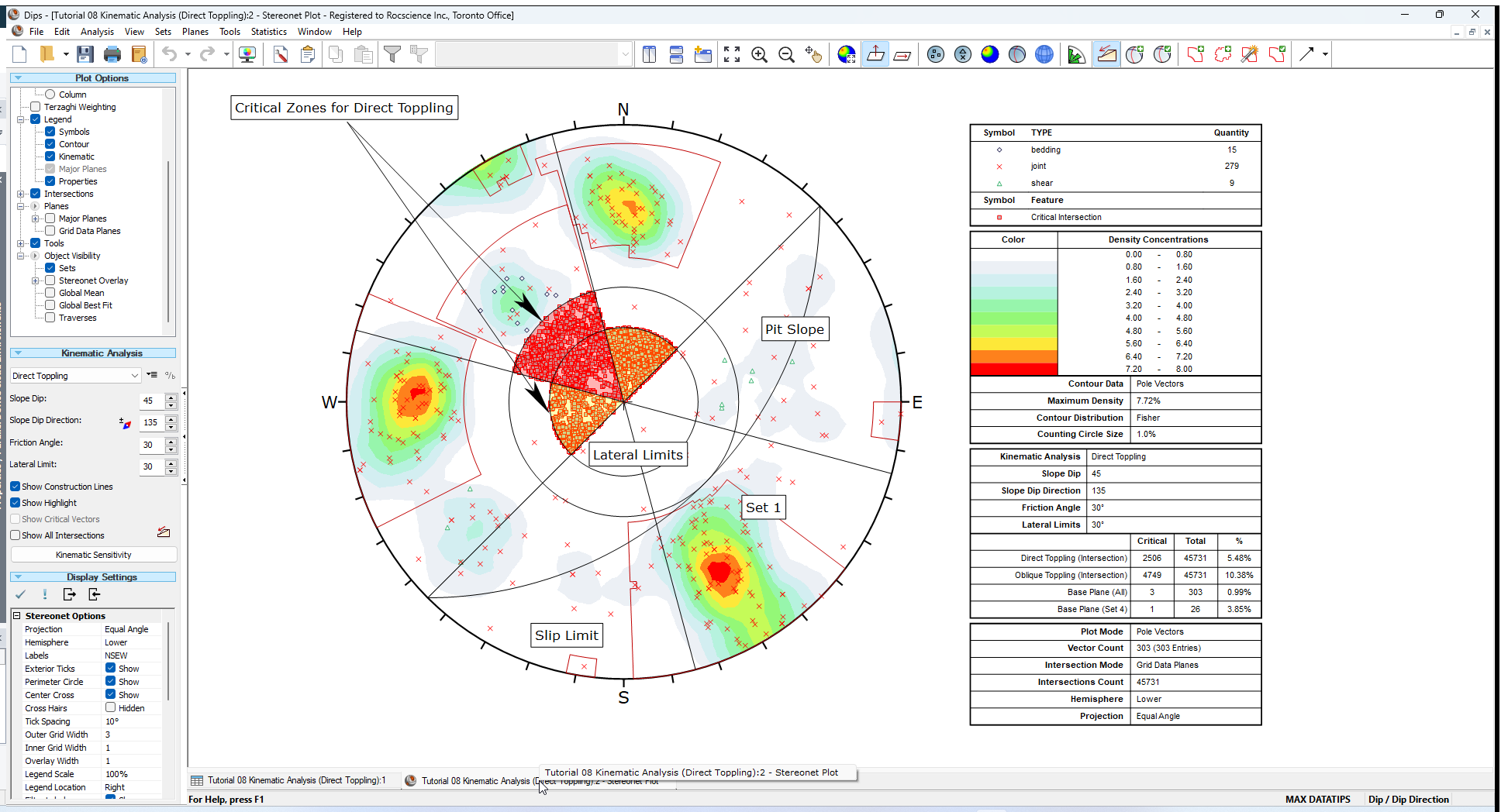
5.0 Direct Toppling
There is one more Kinematic Analysis Toppling failure mode that we have not yet discussed; Direct Toppling.
Direct Toppling involves a different set of assumptions in comparison to Flexural Toppling.
The two primary features of Direct Toppling are:
- Two joint sets intersect to form intersection lines dipping into the slope which can form discrete blocks.
- A third joint set of near horizontal planes act as release planes (or sliding planes) for the discrete blocks.
Direct Toppling analysis is somewhat more complicated than the other analysis modes and is based on the method described in Hudson and Harrison [2]. This is left as an optional exercise to experiment with, for more information see the Direct Toppling Kinematic Analysis topic.
To model Direct Toppling:
- Set the Failure Mode = Direct Toppling in the Kinematic Analysis Sidebar.
6.0 Summary
Kinematic Analysis of rock slope failure modes using stereonets is an extremely useful and easy to understand analysis tool which allows you to quickly evaluate potential failure modes. However keep in mind the following.
- The analyses presented here are just a starting point for more detailed analysis and should always be accompanied by a more thorough field analysis in cases where a risk of failure is indicated.
- Real slopes may exhibit more than one failure mode. It is rare to see pure examples of these failure modes, particularly with the toppling analysis, which may exhibit complex behaviours involving sliding, toppling, rotating etc.
- Even if a Kinematic Analysis indicates risk of failure, this does not necessarily mean that failure will occur, since factors other than kinematics and friction angle may work to increase stability (e.g. joint cohesion, joint persistence etc). Conversely, other factors may decrease stability (e.g. water pressure) of kinematically safe slopes.
- It is important to look beyond statistical results (e.g. mean set plane orientations) and consider major discrete structures such as shear zones which may have a dominant effect on stability due to low friction angles and inherent persistence.
- More detailed analysis including safety factor calculation can be carried out with the Rocscience programs SWedge (wedge analysis), RocPlane (planar analysis), and RocTopple (toppling analysis).
7.0 References
- Goodman, R.E. 1980. Introduction to Rock Mechanics (Chapter 8), Toronto: John Wiley, pp 254-287.
- Hudson, J.A. and Harrison, J.P. 1997. Engineering Rock Mechanics – An Introduction to the Principles, Pergamon Press.
This concludes the tutorial. You are now ready for the next tutorial, Tutorial 09 - Kinematic Analysis (Planar Sliding).