1 - Rigid Analysis of Rectangular Pillar
This tutorial is a simple introductory tutorial that helps you
become familiar with the basic modelling and data interpretation features
of CPillar.
CPillar is a quick and easy-to-use tool for evaluating the stability of surface or underground crown pillars and laminated roof beds.
Topics Covered in this Tutorial:
-
Project Settings
-
Rigid Analysis for Rectangular Pillar
-
Deterministic Analysis
-
Input Data
-
Pillar View
-
Viewing Options
-
Analysis Results
-
Info Viewer
-
Generalized Hoek-Brown (GSI, mi, D) Strength Criterion
-
Water Pressure
-
Sensitivity Analysis
Finished Product:
The finished product of this tutorial can be found in the Tutorial 01 Quick Start (Rigid Analysis).cpil5 file, located in the Examples > Tutorials folder in your CPillar installation folder.
1.0 Introduction
This model represents a square 10 x 10 m pillar with a thickness of 4 meters. There is 1 meter of overburden and 1 meter of free water (6 – (4+1) = 1).
The lateral stress is defined by gravity. Lateral stresses will be calculated based on the Horizontal / Vertical stress ratios (0.8 in both x and y directions).
2.0 Creating a New File
If you have not already done so, run the CPillar program by double-clicking the CPillar icon in your installation folder or by selecting Programs > Rocscience > CPillar > CPillar in the Windows Start menu.
When the program starts, a default model is automatically created. If you do NOT see a model on your screen:
- Select: File > New

Whenever a new file is created, the default input data forms valid pillar geometry, as shown in the image below.

If the CPillar application window is not already maximized, maximize it now so that the full screen is available for viewing the model. You will have a 3D pillar displayed on the screen in isometric orientation.
3.0 Project Settings
The Project Settings dialog allows you to configure the main analysis parameters for your model, such as Units, Analysis Type, and Sampling Method.
3.1 General tab
To open the Project Settings dialog:
- Select Project Settings
 from the toolbar or the Analysis menu.
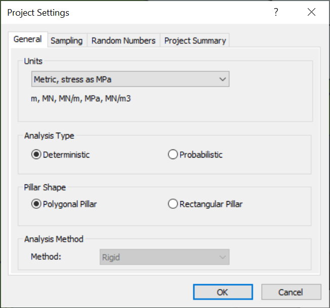
- Navigate to the General tab.
- Units: In this tutorial we are using metric (MPa) units.
- Ensure Units = Metric, stress as MPa (default setting).
- Analysis Type: There are two main analysis types in CPillar: Deterministic, and Probabilistic. The default choice for new files is Deterministic. A Deterministic analysis assumes that all input parameters are exactly known. CPillar computes the Factor of Safety for a single pillar. For a Probabilistic analysis,
statistical input data can be entered to account for uncertainty in
geometry, lateral stress, and strength values. The result is a
distribution of Factors of Safety, from which a Probability of Failure
is calculated. Probabilistic analysis is demonstrated in Tutorial 02 - Elastic Analysis of Rectangular Roof Beam in CPillar.
- Keep Analysis Type = Deterministic.
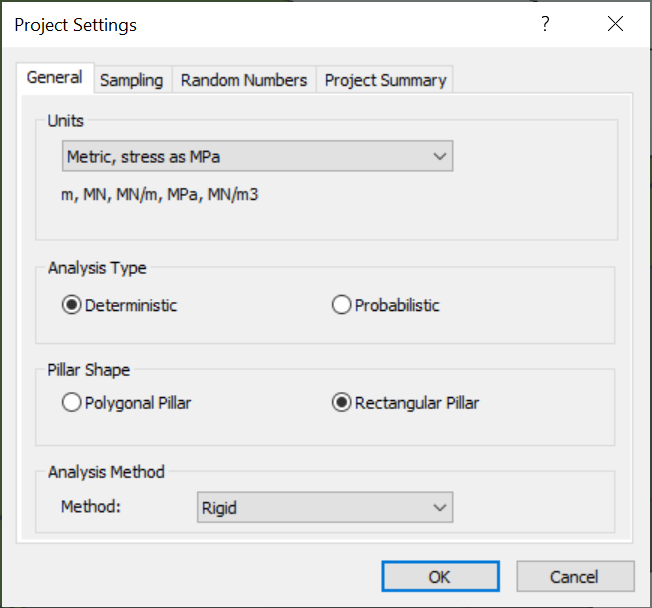
- Pillar Shape: By default, the Pillar Shape is set to Polygonal Pillar which allows for irregular pillar shapes. The default Polygonal Pillar is a 10 by 10 pillar with its stope section geometry defined by 4 vertices. Since we are modeling a square pillar, it is easier to define or modify the geometry in terms of Pillar Length and Pillar Width instead editing vertex coordinates.
- Set Pillar Shape = Rectangular Pillar.
- Set Pillar Shape = Rectangular Pillar.
- Analysis Method: By default, the Analysis Method is set to Rigid. When using Rigid analysis, the pillar is assumed to be a rigid block that fails by plug-sliding along the abutments.
- Keep Analysis Method = Rigid.
3.2 Project Summary tab
- Navigate to the Project Summary tab of the Project Settings dialog.
- Enter CPillar Quick Start Tutorial as the Project Title.
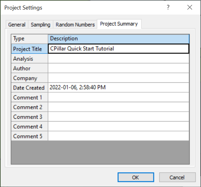
- Leave all other settings as is and click OK to close the Project Settings dialog.
4.0 Input Data
In CPillar, the input parameters are entered in the Input Data dialog. The Input Data dialog is organized under four tabs: Geometry, Stresses, Material Properties, and Rock Mass and Abutment Strength.
To change a parameter, click on the value and enter the new value or
select from the dropdown as necessary. The model will reflect any
changes, immediately.
4.1 Geometry
To set up the analysis in the Input Data dialog:
- Select Input Data
 from the toolbar or Analysis menu.
 - Navigate to the Geometry tab.
- Examine the input data.
- Pillar Dimensions: For a Rectangular Pillar, the Pillar Length, Pillar Width, and Pillar Height define its geometry.
- Abutment Orientation: The pillar is assumed to be of uniform height with vertical abutments.
- Unit Weight: The unit weight for the pillar is defined by Rock Unit Weight.
- Leave the default selections:
Pillar Height = 4 m
Pillar Length = 10 m
Pillar Width = 10 m
Abutment Plunge = 90 deg
Abutment Trend = 0 deg
Rock Unit Weight = 0.027 MN/m3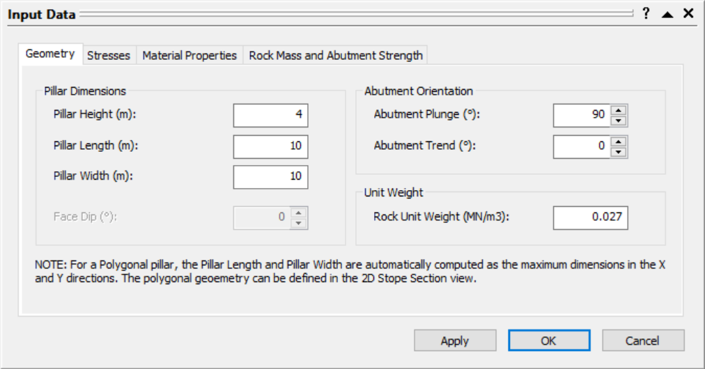
4.2 Stresses
- Navigate to the Stresses tab of the Input Data dialog.
- Examine the input data.
- Lateral Stress: When Stress Type = Gravity is selected, the lateral stresses are computed based on the Locked In Stress and the horizontal/vertical Kx and Ky values.
- Overburden: Overburden can be added to the model be specifying the Overburden Thickness and Overburden Unit Weight.
- Water: Water can be added to the model be specifying the Water Height and Water Unit Weight. The Pillar Is Permeable option allows the user to specify if effective stresses are subject to the effects of water pressure. By default (Pillar Is Permeable = No), which means that pore water pressures are not taken into account.
- Leave the default selections:
Stress Type = Gravity
Locked In Stress = 0 MPa
Kx = 0.8
Ky = 0.8
Overburden Thickness = 1 m
Overburden Unit Weight = 0.02 MN/m3
Water Height = 6 m
Water Unit Weight = 0.00981 MN/m3
Pillar Is Permeable = No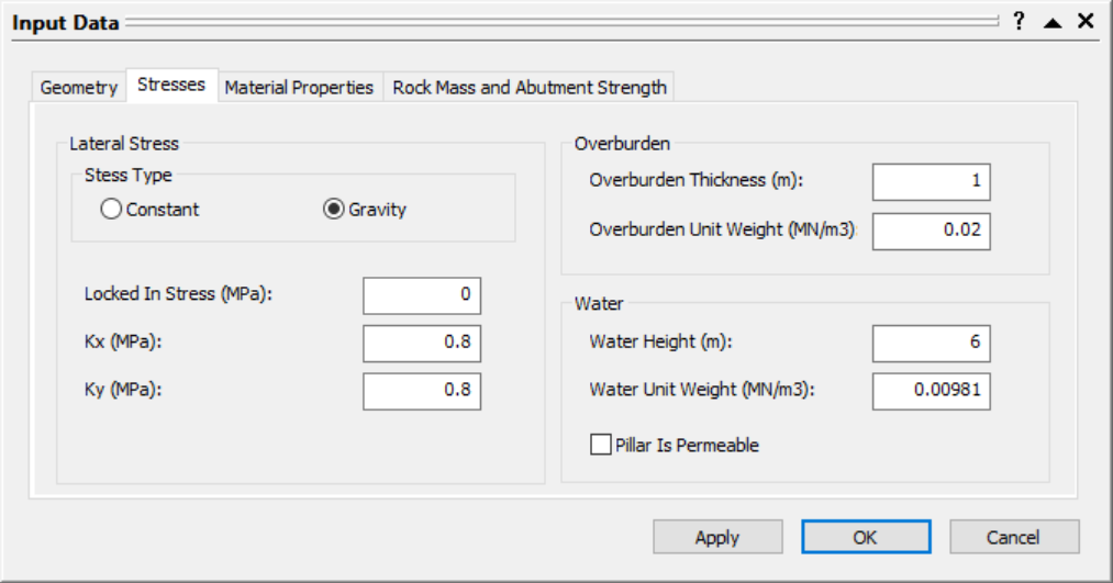
4.3 Material Properties
- Navigate to the Material Properties tab of the Input Data dialog. At least one material property is defined at all times.
- Examine the input data.
- For Material Properties 1: Set the Model = Generalized Hoek-Brown (GSI, mi, D). The parameters or relevance can be defined for the shear strength Model selected.
- In this example, we will use the following (default) parameters:
Geological Strength Index GSI = 50
Rock Constant mi = 10
Disturbance Factor = 0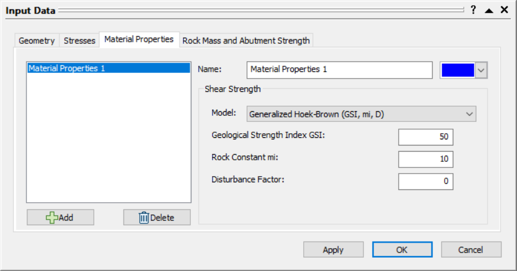
4.4 Rock Mass and Abutment Strength
- Navigate to the Rock Mass and Abutment Strength tab of the Input Data dialog.
- Examine the input data.
- Rock Mass: Rock Mass parameters characterize the entire rock and are not specific to each Abutment. The Intact UCS applies to all Hoek-Brown shear strength calculations.
- Abutments: Different shear strength Properties can be assigned to each Abutment from the Material Properties tab. Since we only have one Property defined (i.e., Material Properties 1), all four abutments are automatically assigned Material Properties 1.
- Leave the default selections:
Intact UCS = 60 MPa
Abutment 1 = Material Properties 1
Abutment 2 = Material Properties 1
Abutment 3 = Material Properties 1
Abutment 4 = Material Properties 1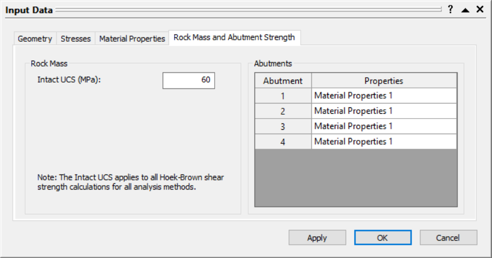
- Select OK to apply the changes and exit the Input Data dialog.
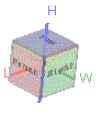
The 3D Pillar View shows an isometric perspective of a deterministic 3D pillar model with principle stresses and dimensions labeled:
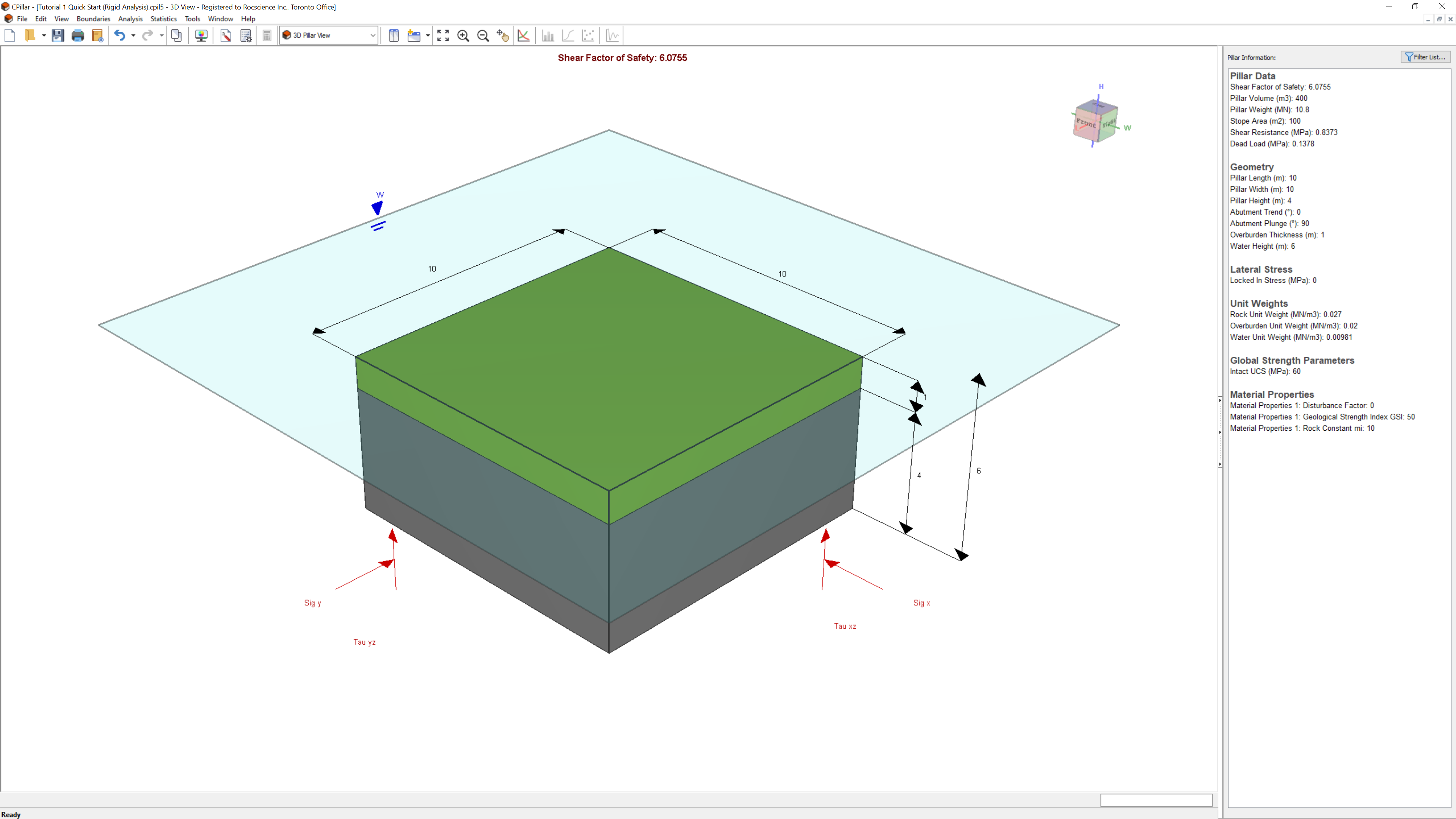
5.0 Analysis Results
To ensure the latest analysis results are always displayed, CPillar automatically computes an analysis whenever:
-
A file is opened, or
-
Input data is entered or modified in the Input Data dialog.
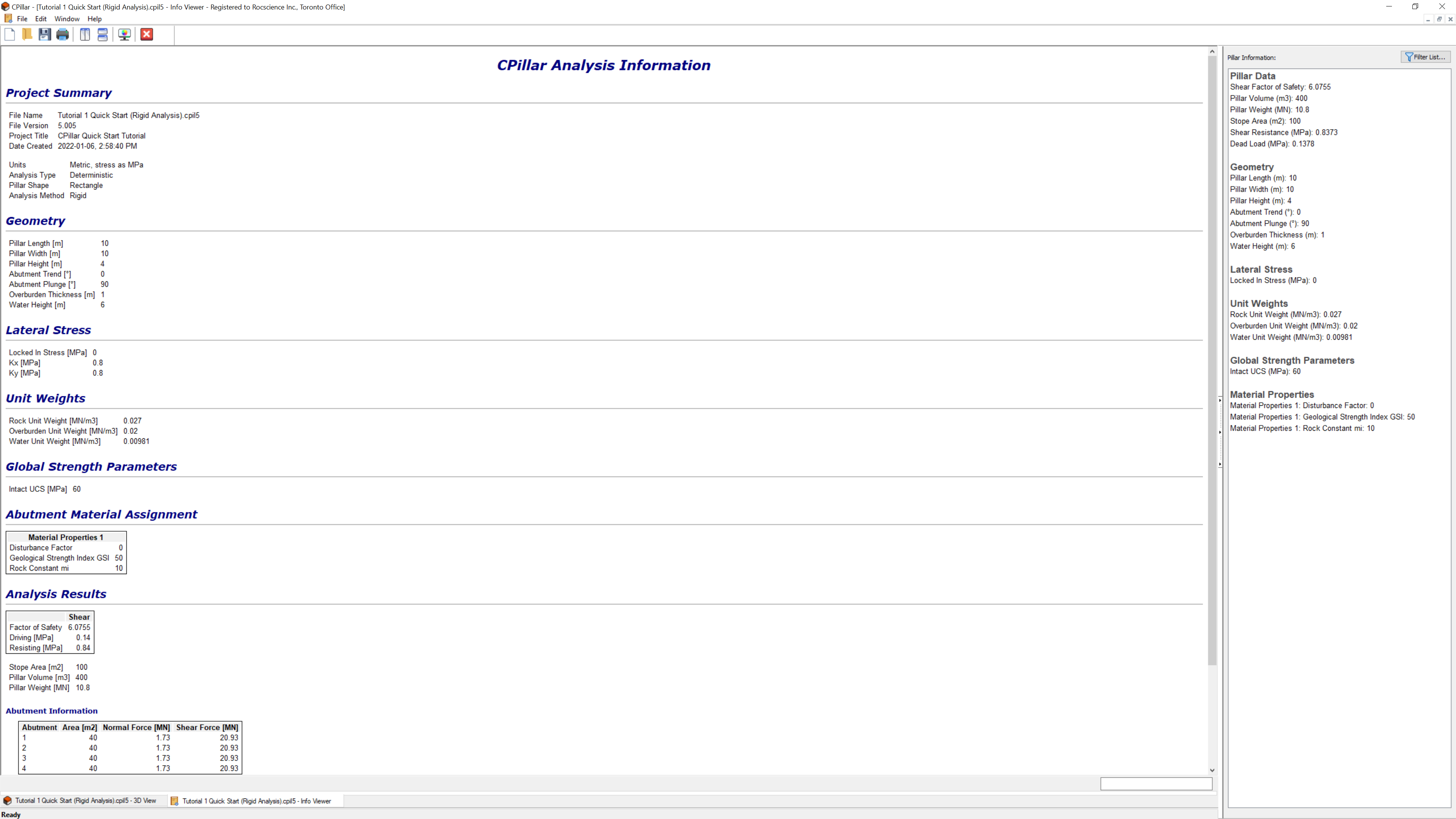
The primary result from a CPillar Deterministic Analysis is the pillar Factor of Safety. The Factor of Safety is displayed at the top-center of the 3D Pillar View and in the Pillar Information pane. The Pillar Information pane appears in the Sidebar on the right side of the CPillar application window and displays a summary of analysis results.
Note that, since this is a Rigid analysis, shear is the only failure mode; as such shear is the only failure result displayed. The Shear Factor of Safety is 6.0755.
6.0 Info Viewer
The CPillar Info Viewer displays a comprehensive listing of input data and analysis results.
To open the viewer:
- Select Info Viewer
 on the toolbar or on the Analysis menu.
To copy data in the Info Viewer to the Clipboard or save it to a file:
- Right-click in the view and access the various options in the pop-up menu.
To close the Info Viewer:
- Click the Close Window
 button on the toolbar or click the X in the upper-right corner of the view.
7.0 Viewing Options
In this section of the tutorial, you'll learn about some of the viewing options and shortcuts available in the 3D Pillar View (the previous view).
To switch back to the 3D Pillar View:
- Select 3D Pillar View
 view tab at the bottom of the window.
The Pillar View shows an Isometric orientation of the model, by default.
To toggle between the Top, Front, Left, Right, and Bottom orientations:
- Click on the faces of the View Cube in the upper right corner of the model window.
- Select Display Orientation on the View menu or right-click menu.
7.1 Rotating the Model
Within the Pillar View window, you can view the CPillar model at any angle by interactively rotating it with the left mouse button as follows:
-
Press and hold the left mouse button anywhere in the Pillar View window. Notice that the cursor changes to a circular arrow symbol
 to indicate that you may rotate the model.
-
Keep the left mouse button pressed and move the cursor around to rotate the model according to the direction of movement of the cursor.
-
To exit the rotation mode, release the left mouse button. The cursor reverts to the normal arrow symbol.
To reset the rotation to the default viewing angle:
- Select Reset View
 from the View menu or right-click menu.
7.2 Zooming and Panning
The following zoom and pan options are available in the 3D Pillar View:
-
Zoom All
 – Reset the model to its default size and location in the view.
-
Zoom In
 – Zoom in to 90 % of the original area.
-
Zoom Out
 – Zoom out to 111% of the original area.
-
Pan
 – Translate the model left, right, up, or down within the view
To access the zoom and pan options:
- Select the Zoom sub-menu of the View menu or buttons in the toolbar.
- Use various keyboard and mouse shortcuts as follows:
-
Rotate the mouse wheel forward or backward to zoom in or out.
-
Use the F2, F4, and F5 function keys to access the Zoom Extents, Zoom Out, and Zoom In functions, respectively.
-
To use the Pan function, click and hold the mouse wheel while dragging the mouse to pan the model within the view.
-
For more detailed help on zooming and panning, see Zoom and Pan.
8.0 Sensitivity Analysis
The final section of the tutorial demonstrates the Sensitivity Analysis feature. In a Sensitivity Analysis, individual variables can be varied among user-defined minimum and maximum values while all other input parameters remain constant. This allows you to determine the effect of individual variables on the Factor of Safety.
We will use Sensitivity Analysis to show that the worst possible direction to show the effect of Water Height on the Factor of Safety.
-
Select Sensitivity Analysis
 on the toolbar or on the Analysis menu.
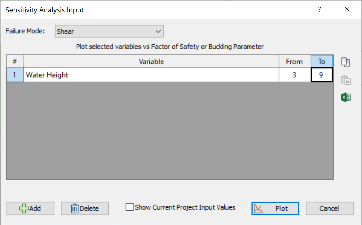
- In the Sensitivity Analysis Input dialog, select Variable = Water Height from the dropdown.
-
Enter From = 3 and To = 9 m.
-
Click Plot.
You should see the following Sensitivity Plot.
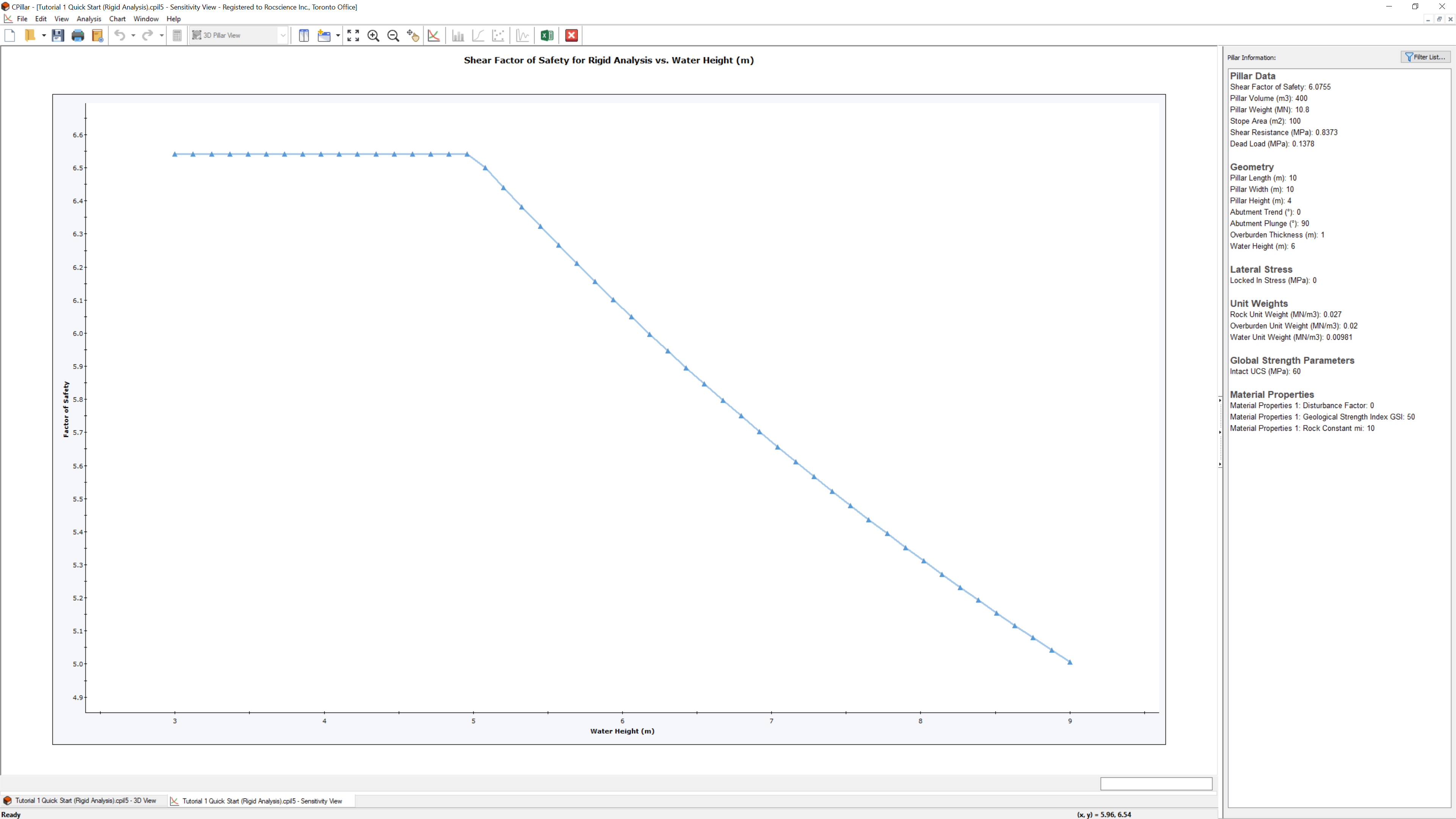
Notice that the Factor of Safety remains unchanged with increasing Water Height, when Water Height <= Pillar Height + Overburden Thickness. This is due to the impermeable (Pillar Is Permeable = No) pillar assumption whereby the water pressures have no impact on the effective lateral stresses. However, once the Water Height > Pillar Height + Overburden Thickness, the free water above the overburden is taken into account as a deadload. Therefore, beyond this point, the Factor of Safety decreases with increasing Water Height.
This concludes the tutorial. You can now proceed to Tutorial 02 - Elastic Analysis of Rectangular Roof Beam in CPillar.